1
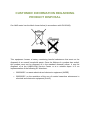
OPERATION MANUAL CABLE TV LEAKAGE METERS AMS2010 SERIES All rights reserved. This document contains information proprietary to KABELKOM. No part of this publication may be used, reproduced, stored in a retrieval system, or copied in any manner without the prior written permission of KABELKOM. The information in this user’s manual is subject to change without prior notice. The detailed information about software and copyright is present on the CD (license). The software described in this manual is delivered under a license agreement. The software may be used or copied only in accordance with the terms of the agreement. Microsoft and Windows are registered trademarks of Microsoft Corporation. Windows 95/98/ME/2000/NT/XP/Vista and ActiveSync are trademarks of Microsoft Corporation. Google Earth is a registered trademark of Google, Inc. Product names mentioned herein may be trademarks and/or registered trademarks of their respective owners/companies. NOTICE THE MANUFACTURER OR RESELLER SHALL NOT BE LIABLE FOR ERRORS OR OMISSIONS CONTAINED IN THIS MANUAL AND SHALL NOT BE LIABLE FOR ANY CONSEQUENTIAL DAMAGES, WHICH MAY RESULT FROM THE PERFORMANCE OR USE OF THIS MANUAL, EQUIPMENT OR SOFTWARE. © KABELKOM 2012 All rights reserved. KABELKOM ul. Bukowa 30 43-300 Bielsko-Biała POLAND E-mail: [email protected] Jan 2012 Internet: http://www.kabelkom.pl Ver. 1.3 WARRANTY KABELKOM warrants that all products manufactured by KABELKOM conform to KABELKOM’s published specifications as well as the essential requirements of the European Union stated in the EU Directives and are free from defects in materials and workmanship for a period of one (1) year from the date of delivery to the original Buyer, when used under normal operating conditions and within the service conditions for which they were designed. This warranty is not transferrable and does not apply to used or demonstration products. The obligation of KABELKOM arising from a Warranty claim shall be limited to repairing, or at its option, replacing without charge, any assembly or component (except batteries) which in KABELKOM’s sole opinion proves to be defective within the scope of the Warranty. In the event KABELKOM is not able to modify, repair or replace nonconforming defective parts or components to a condition as warranted within a reasonable time after receipt thereof, Buyers shall receive credit in the amount of the original invoiced price of the product. KABELKOM must be notified in writing of the defect or nonconformity within the Warranty period and the affected Product returned to KABELKOM’s factory, designated Service Provider, or Authorized Service Center within thirty (30) days after discovery of such defect or nonconformity. Buyer shall prepay shipping charges and insurance for Products returned to KABELKOM or its designated Service Provider for warranty service. KABELKOM or its designated Service Provider shall pay costs for return of Products to Buyer. KABELKOM shall have no responsibility for any defect or damage caused by improper storage, improper installation, unauthorized modification, misuse, neglect, inadequate maintenance, accident or for any Product which has been repaired or altered by anyone other than KABELKOM or its authorized representative or not in accordance with instructions furnished by KABELKOM. The Warranty described above is Buyer’s sole and exclusive remedy and no other warranty, whether written or oral, expressed or implied by statue or course of dealing shall apply. KABELKOM specifically disclaims the implied warranties of merchantability and fitness for a particular purpose. No statement, representation, agreement, or understanding, oral or written, made by an agent, distributor or employee of KABELKOM, which is not contained in the foregoing Warranty will be binding upon KABELKOM, unless made in writing and executed by an authorized representative of KABELKOM. Under no circumstances shall KABELKOM be liable for any direct, indirect, special, incidental, or consequential damages, expenses, or losses, including loss of profits, based on contract, tort, or any other legal theory. Dear AMS2010 User, Thank you very much for purchasing the AMS2010 series meter! It has been designed for your satisfaction. We do hope that the meter will effectively help you to find leakage and ingress sources in your CATV network. Although it is a very modern and sophisticated tool, the operation with the meter is quite easy. However, we suggest you to read this manual carefully before you start to work with it. If you have any remarks concerning the meter, its functions, parameters or possible improvement, please contact us. Enjoy the work with your new AMS2010 meter! Sincerely, KABELKOM team CUSTOMER INFORMATION REGARDING PRODUCT DISPOSAL Our AMS meter has the label shown below (in accordance with EN 50419). This equipment houses a battery containing harmful substances that must not be disposed of as normal household waste. Once the lifetime of a product has ended, this product must not be disposed of in the standard domestic refuse. It may be disposed of at the KABELKOM Service Center or at a suitable depot. It is an implementation of the following EC directives: • 2002/96/EC on waste electrical and electronic equipment (WEEE) • 2002/95/EC on the restriction of the use of certain hazardous substances in electrical and electronic equipment (RoHS). Contents 1 INTRODUCTION................................................................................................................................ 7 2 PREPARATION FOR OPERATION................................................................................................... 9 2.1 General Information.................................................................................................................... 9 2.2 Inspection................................................................................................................................... 9 3 GETTING ACQUINTED WITH THE AMS2010.................................................................................11 4 USING THE AMS2010..................................................................................................................... 13 4.1 Switching on/off the meter ....................................................................................................... 13 4.2 Main Menu................................................................................................................................ 13 4.3 Leakage+GPS mode (AMS2010 GPS SE)...............................................................................14 4.4 Leakage mode.......................................................................................................................... 17 4.5 FastLeak mode......................................................................................................................... 19 4.6 Config mode............................................................................................................................. 20 4.7 Info mode.................................................................................................................................. 27 5 Visualization of measurement results............................................................................................... 29 6 Troubleshooting................................................................................................................................ 40 7 User support..................................................................................................................................... 42 APPENDIX 1......................................................................................................................................... 43 APPENDIX 2......................................................................................................................................... 45 1 INTRODUCTION The AMS2010 series meters are high performance hand-held meters designed for cable TV technicians to make RF leakage control and measurement easy. They are highly sensitive devices designed to measure leakage magnitude and efficiently find leakage and ingress sources. The AMS2010 series meters allow leakage measurement in analog, analog/digital and digital CATV networks. The meters can be used during pedestrian and mobile (vehicle) patrols in the field. The detection efficiency and reduction of false alarms in noisy environments have been achieved by tagging the measured signal. The meters use a unique signal tagging method (patent pending) suitable for analog as well as digital cable TV networks. The meters are compatible with the LT1000 signal tagger (made by JDSU, former Acterna, WWG, or Wavetek). In areas where many cable TV networks co-exist you can determine if a detected leak is radiating from the network that you are testing. The extended models (AMS2010 GPS and AMS2010 GPS GE) have built-in GPS receivers and are specialized automatic leakage control systems. They save leakage levels together with the geographical coordinates. The measurement files can be processed in the attached software (StealthExplorer) or can be directly downloaded to Google Earth (AMS2010 GPS GE) for visualization on a map. The AMS2010 meters make the accurate leakage measurements needed for verifying compliance with government regulations (e.g., EN 50083-8 in the European Union countries or FCC Part 76 of the Code of Federal Regulations Title 47 in the U.S.A.). The type of antenna and the distance from the leak are taken into consideration when measuring field strength. The device has been developed by people who have been, by themselves, detecting leakage sources in cable TV networks for many years. A compromise has been reached between the meter dimensions (180x90x45 mm), weight (approx. 0.35 kg) and measurement/detection accuracy. The screen and keyboard have a light source to improve visibility in darkness and the comfort of operation. The meter has been designed to be time and labor effective, with an economic price (versions can be tailored to customer's needs and requirements) and as a technologically sophisticated device for a quick detection of common and problematic leakage problems. The meter is portable and easy for handling. It can charged via the USB port as well as from the external charger. The meters cooperate with the DS docking station and can be mounted in a vehicle. The DS station together with AMS2010 can transmit the data about found leak sources online via GSM or HFC networks. The DS station is backward compatible with the CLI950/1450/1750 meters manufactured by JDSU (former Acterna, WWG or Wavetek). The operation with the meter is easy due to the simple and intuitive menu as well as the alphanumeric keyboard (similar to a mobile phone keyboard). The AMS series can work with computers using any operating system like Linux, MacOS or Microsoft Windows. The computer should be connected to the Internet. The basic differences among AMS meters/detectors are as follows: • AMS2010 detector does not have professional SAW filters and a GPS receiver • AMS2010 GPS GE – has a professional SAW (surface acoustic wave) filter, a built-in GPS receiver; it automatically saves the pedestrian/mobile patrol measurement results in a file using the format compatible with GoogleEarth; the measurement file with measurement results obtained automatically during mobile or pedestrian patrols can be processed and visualized in StealthExplorer (also manually exported to Google Earth). To display the GoogleEarth files with measurement results, the AMS2010 GPS GE should be connected to the USB port of a computer, then the proper file name should be chosen and the viewing option should be activated. 2 PREPARATION FOR OPERATION 2.1 General Information Before operating the AMS2010 meter, make sure you carefully inspect the product and read the operation manual. WARNING Only trained service personnel who is aware of the hazards involved (for example, fire or electric shock) should perform repairs on the AMS2010 meter! Tuning the AMS2010 meter and replacing components influencing the accuracy of measurements without authorized service personnel is strictly prohibited and may cause inaccurate or improper operation of the meter. 2.2 Inspection The AMS 2010 package includes (the CLI upgrade package does not contains the antennas): • the AMS2010 meter • DC power supply/charger module • USB cable • vehicle monopole antenna • handheld dipole antenna. Upon receipt of the package, check the availability of the items contained in it against the list provided. Perform an external examination to make sure your AMS2010 is free from any visible physical or mechanical damage. If the meter has been stored in an extreme environment which exceeds the rated operating conditions, place the unit inside a temperature controlled facility with normal operating conditions for 2 hours prior to operation. The battery of the meter is fully charged before delivery. However, if the meter cannot be switched on, connect the meter with the charger. NOTE In order to obtain the most accurate measurement results, the AMS2010 meter should always have a valid calibration. You should also install the visualization software – StealthExplorer. Simply download the software from KABELKOM's Web page and run it. The installation program will guide you through the installation process. If you want to use Google Earth for visualization of the results, make sure that your PC is connected to the Internet and has Google Earth software installed. 3 GETTING ACQUINTED WITH THE AMS2010 Fig. 1 and 2 illustrate the location of controls, indicators and connectors. Fig. 1. General view of the meter with the keyboard Fig. 2. Location of input BNC, USB and charger connectors The basic parameters of the AMS2010 can be found in APPENDIX 1. The button is used for switching the meter on or off. The arrow keys: left arrow right arrow , up arrow and down arrow , allow to choose and edit the meter parameters and the current operation mode. The ENTER key enables the current command or begins an operation in the chosen measurement mode. The “ESC” key is used to stop the measurement process or to leave a menu option. With the key you can switch on or off the USB connector. The software keys , , are used for choosing the option described above them on the screen (the options depend on the chosen function of the meter, so the software keys may be inactive in some modes). The BNC connector is for signal input from a measurement antenna. The USB connector can be used for data transfer to your PC and for charging the meter battery by the charger or your PC. If the meter detects the tagger or taggers and the leakage level is above a certain threshold (20 µV/m), you can hear a beeping sound. You can switch on/off the USB port at any time using the key. When the port is off, the meter uses its internal memory. When the port is on, the meter resources are available to any PC connected to the USB port. You can copy the files from the AMS2010 to your PC. When you are in the Main menu, press the K2 software key. You should see the “USB Accept” message on the screen. Simply connect the meter with your PC using an USB cable. The PC should recognize the meter memory as an external disk drive (like a pen drive). NOTE Some computer models may require an USB cable with an external ferrite choke for proper data transmission. AMS2010 can work in the following modes of operation: • Leakage • Leakage+GPS • FastLeak • Spectrum (will be available in the future) • Configuration • Information The icon Gen is not used. The modes and available options have been described in Section 4. 4 USING THE AMS2010 The best way to learn about the AMS2010 is to use it. The operation modes have been described step by step in the subsequent sections. 4.1 Switching on/off the meter To switch on the meter (or switch it off) press the red key for at least 2 seconds. If you are in the Leakage+GPS mode (GPS GE model only), after pressing the red key the meter stops the measurement and saves the measurement data in a measurement file. In order to switch off the meter you should press the key once again. 4.2 Main Menu After the meter has been switched on, you will see the Main Menu screen (Fig. 3). Fig. 3. Main Menu of AMS2010 You can see the battery voltage, the current consumption and the current time. To choose the required mode of operation, highlight a proper icon (in Fig. 3 the Leakage+GPS mode is highlighted) with the arrow keys (left arrow ) and finally press the Enter key . You can choose the following operation modes: Leakage , Fast Leak , Spectrum or right arrow , Leakage with GPS (will be available in the future), Wi-Fi available in the future), Configuration and Info . (will be 4.3 Leakage+GPS mode (AMS2010 GPS SE) If you want to begin the leakage measurement with the GPS coordinates and save the results in a file, choose the Leakage+GPS mode icon You will see the Leakage+GPS mode screen (Fig. 4). and press Enter . Fig. 4. Leakage+GPS mode screen At the beginning, the screen displays the GPS info. If there is no GPS signal (e.g., inside a building) or you do not want to use the GPS option, simply press Enter immediately after choosing the Leakage+GPS mode. If the GPS receiver is enabled and the GPS antenna can see at least four GPS satellites on the sky, after some time the GPS receiver will be able to determine the coordinates. The time necessary for initialization of the GPS receiver may vary from a few seconds up to 3 minutes. NOTE The GPS accuracy depends on the number of satellites seen by the GPS antenna, the satellite localization in the sky and the surrounding obstacles (buildings, trees, trucks, etc.) which can block or reflect the radio waves arriving from the GPS satellites. The accuracy changes with time. The path obtained during the GPS measurements may not correlate exactly with the roads as in the case of navigation software and is not a symptom of the meter malfunctioning. This is due to the different operation of the GPS navigation systems which artificially bind the current GPS position with the nearest road on a map. The AMS2010 saves the GPS data without any modifications. The Leakage+GPS screen displays the mode name, the measurement frequency (121.400 MHz), the tagger 1 and 2 frequencies (22 and 23 Hz, respectively), and the current leakage value (E field intensity 3.6318 µV/m in Fig. 4). The screen also shows the current time (01:37), the battery status, the antenna type (Hand), the GPS receiver status (No GPS Fix) and the actual distance from the leakage source (3 m). You can change the antenna type using the F2 software key or the units using the F3 software key. If the meter detects the tagger, the icon (!TAG1! and/or !TAG2!) will be shown. You can change the measurement and tagging frequencies, the actual distance, the antenna type, the distance to the leak source and enable/disable the GPS receiver in the Config Menu (see Section 4.6). NOTE The signal tagger should be installed in the cable TV headend before measurements. It is suggested to use the KABELKOM’s AM2 signal tagger. However, it is possible to use any analog TV signal modulator or CW generator together with the LT1000 signal tagger (JDSU, Wavetek). Frequency stability is critical for good measurements (the AMS2010 uses very precise narrowband filters) and should be verified before leakage measurements. NOTE The meter can measure leakage from analog and/or digital CATV networks. In case of analog networks the power level of the tagged TV or CW carrier used for leakage measurement should be equal to the power level of typical analog TV video carriers. The power level of the CW carrier for digital networks (digital option available with KABELKOM’s AM2 tagger only) should be at the power level of digital channels (see Fig. 5), otherwise the leakage value will be incorrect. Fig. 5. Relationship between the power levels of digital carriers and tagged carriers for leakage measurement If the leakage level is higher then a threshold value (20 µV/m) and the meter has detected the correct tagger signal (one tagger frequency – the conventional tagging method or two tagger frequencies – KABELKOM’s method), the meter will beep. The acoustic signalization is very helpful during mobile patrols when a driver cannot observe the screen of the meter. If you use the conventional tagging method, you should enter the same value for TAG 1 and TAG 2 frequencies in the Configuration menu (see Section 4.6). The AMS2010 GPS GE allows for saving the measured values together with the geographical coordinates of the measurement points in the meter memory. The file has the .lv4 extension and is saved in the folder ddmmyy where dd stands for the day, mm for the month and yy for the year of the measurement. The .lv4 files can be downloaded to StealthExplorer and processed in order to prepare a map with the leakage measurement results. The AMS GPS GE saves the .lv4 file together with a .KML file. The measurement files with the .KML extension can be downloaded directly to Google Earth for visualization and do not require any processing. However, if you want to obtain more information from the gathered measurement data, you should use StealthExplorer. The detailed description of StealthExplorer can be found in Section 5. The meter begins to save the data automatically (AMS2010 GPS GE) after the Leakage+GPS mode has been chosen and the GPS position has been fixed. If you want to stop the measurement, press the “Esc” key be automatically saved. Pressing the power key saves the measurement file. . The measurement files will also stops the measurement and If you want to choose the antenna type, press the key consecutively to sequence through the available antenna types (you may choose Hand, Car, Upstream and Misc antennas). For accurate measurements, you should be sure that you have selected the correct type for the antenna you are currently using. The most accurate and repeatable measurements are made using a dipole antenna located at the required reference distance (usually 3 m). You can also make approximate measurements (pedestrian or mobile patrols; leaks in an inaccessible area) up to 30 meters away by entering the estimate distance from the leak. The AMS2010 will calculate what the equivalent field amplitude would be at the reference distance. These measurements (especially done during the mobile patrols) are adequate for grading found leaks and prioritizing your repair orders based on leak severity. The antenna type is displayed on the bottom of the screen above the key. The characteristics for each antenna type (except handheld dipole) are programmable and can be set up during the calibration procedure. The antenna calibration is performed for antennas which parameters are not known. This procedure is highly recommended for mobile antennas. The vehicle body acts like a part of the antenna, so the antenna characteristics depend on the antenna position on the vehicle roof and the vehicle model. The calibration procedure should be repeated after the antenna position on the roof has been changed or when the antenna has been moved to another vehicle. The calibration requires a reference antenna with well-known characteristics. The most common reference antenna is the half-wavelength dipole. The AMS2010 has predefined parameters for this antenna type. If you want to measure the leak amplitude with the half-wavelength dipole, choose the dipole antenna Hand in the Config Menu or by pressing the F2 key repeatedly until you see Hand on the screen. The calibration procedure requires a stable leakage source. You can use a controlled leakage source from your cable TV network (using an antenna or a wire connected to the subscriber’s outlet or an amplifier) or a signal generator (like the portable test signal generator AMS2011 Transmitter from KABELKOM) with an antenna. The correct calibration means that the leak amplitude measured with the reference antenna has the same value as the leak amplitude measured with the calibrated antenna (you should modify the correction factor as long as the leakage value is the same as for the reference antenna). 4.4 Leakage mode If you want to begin the leakage measurement without saving the measurement data with the GPS coordinates, choose the Leakage mode icon You will see the Leakage mode screen (Fig. 6). and press Enter . Fig. 6. Leakage mode screen The Leakage screen displays the measurement frequency (121.400 MHz), the tagger 1 and 2 frequencies (22 and 23 Hz, respectively), the actual distance to the leak source (3 m) and the current leakage value (E field intensity 4.8208 µV/m in Fig. 6). The screen also shows the current time (06:33), the battery and charger status, and the antenna type (Hand). If the meter detects the tagger, the icon (!TAG1! and/or !TAG2!) will be shown on the bottom of the screen. The meter also allows for a leakage measurement in the upstream or downstream frequency range. The upstream and downstream measurement frequencies can be defined in the Configuration mode (see Section 4.6). Choose the Upstream option by pressing the F2 key. Please remember that you should also change the antenna and enter the correct calibration factor (antenna factor) for a given upstream frequency. NOTE The signal tagger should be installed in the cable TV headend before measurements. It is suggested to use the KABELKOM’s AM2 signal tagger. However, it is possible to use any analog TV signal modulator or CW generator together with the LT1000 signal tagger (JDSU, Wavetek). Frequency stability is critical for good measurements (the AMS2010 uses very precise narrowband filters) and should be verified before leakage measurements. NOTE The meter can measure leakage from analog and/or digital CATV networks. In case of analog networks the power level of the tagged TV or CW carrier used for leakage measurement should be equal to the power level of typical analog TV video carriers. The power level of the CW carrier for digital networks (digital option available with KABELKOM’s AM2 tagger only) should be at the power level of digital channels (see Fig. 5), otherwise the leakage value will be incorrect. If the leakage level is higher then a threshold value (20 µV/m) and the meter has detected a valid tagger signal (one tagger frequency – the conventional tagging method or two tagger frequencies – KABELKOM’s method), the meter will beep. The acoustic signalization is very helpful during mobile patrols when a driver cannot observe the screen of the meter. If you use the conventional tagging method, you should enter the same value for TAG 1 and TAG 2 frequencies in the Configuration menu (see Section 4.6). If you want to stop the measurement, press the Escape key key also stops the measurement. . Pressing the power If you want to choose the antenna type, press the 2 key consecutively to sequence through the available antenna types (you may choose Hand, Car, Upstream and Misc antennas). For accurate measurements, you should be sure that you have selected the correct type for the antenna you are currently using. The most accurate and repeatable measurements are made using a dipole antenna located at the required reference distance (usually 3 m). You can also make approximate measurements (pedestrian or mobile patrols; leaks in an inaccessible area) up to 30 meters away by entering the estimate distance from the leak (see Section 4.6 for details). The AMS2010 will calculate what the equivalent field amplitude would be at the reference distance. These measurements (especially done during the mobile patrols) are adequate for grading leaks you have found and prioritizing your repair schedule based on leak severity. The antenna type is displayed on the bottom of the screen. The characteristics for each antenna type are programmable and can be set up during the calibration procedure. The antenna calibration is performed for antennas which parameters are not known. This procedure is highly recommended for mobile antennas. The vehicle body acts like a part of the antenna, so the antenna characteristics depend on the antenna position on the vehicle roof and the vehicle model. The procedure should be repeated periodically or after the antenna position on the roof has been changed or the antenna has been moved to another vehicle. The calibration requires a reference antenna with well-known parameters. The most common reference antenna is the half-wavelength dipole. The AMS2010 has predefined parameters for this antenna type. If you want to measure the leak amplitude with the half-wavelength dipole, choose the dipole antenna Hand in the Config Menu or by pressing the key repeatedly until you see Hand on the screen. The calibration procedure requires a stable leakage source. You can use a controlled leakage source from your cable TV network (using an antenna or a wire connected to the subscriber’s outlet or an amplifier) or a signal generator (like the portable test signal generator AMS2011 Transmitter from KABELKOM) with an antenna. The correct calibration means that the leak amplitude measured with the reference antenna has the same value as the leak amplitude measured with the calibrated antenna. 4.5 FastLeak mode This mode allows you to quickly scan for leak sources nearby. You can use it when you are locating a specific leakage source at home, in a corridor, along a trunked cable, in a street or headend etc. If you have a directional antenna (a dipole, for example), you can quickly identify the leakage source using a triangulation method. The meter operating in the FastLeak mode shows the results on the screen much faster than during regular measurements. The move (rotation) of the antenna kept in your hand is immediately visible on the screen. If you want to work in the FastLeak mode, choose FastLeak mode icon and press Enter . The meter will display the FastLeak screen (Fig. 7). You can observe the measured leakage values in a similar way when you use the normal leakage mode (see Section 4.4). Fig. 7. FastLeak mode screen 4.6 Config mode The Config mode allows for setting up all the parameters necessary for correct operation of the meter. If you want to choose the Config mode, highlight the icon with the left and right arrow keys in the Main menu and press Enter Configuration Menu will appear on the screen (Fig. 8). . The Fig. 8. Configuration Menu If you want to set up the parameters related to leakage measurements, highlight Measure with the up-down arrow keys and press Enter You will see the screen similar to this shown in Fig. 9. Fig. 9. Measure Configuration Menu or the right arrow key. Press the left arrow key Menu. or Esc if you want to go back to the Configuration If you want to change the test frequency, highlight Measure Freq. in the menu and press Enter or the right arrow key. Using the up or down arrow keys and right arrow keys change the frequency in the dialog field and press the left arrow key or Esc in order to go back to the Config menu. If the entered value is outside the valid frequency range, the frequency field will display “---.---“ and you should enter the correct value again. Highlight TAG 1/2 Frequency and press Enter or the right arrow if you want to change the tagger frequency (see Fig.10). Choose the proper frequency value using the up or down arrow keys back to the Config Menu. . Press the left arrow key or Esc to go Fig. 10. Setting the tagger 1 frequency NOTE If you use the AM2 signal tagger from KABELKOM, you should enter two independent values for TAG1 and TAG2. If you use the LT1000 from JDSU or a signal generator with internal AM modulation, you should enter the same value for TAG1 and TAG2. Highlight Distance (setting the actual distance to the leakage source (Fig. 11), Level units (µV/m or dBm – Fig. 12) or Antenna type (Hand for half-wavelength dipole, Car for a vehicle monopole, Upstream for a CB monopole and Misc for any other antenna – Fig. 13) and press Enter or the right arrow key if you want to change one of these parameters. Choose the proper parameter value using the up or down arrow keys . Press the left arrow key the Measure Configuration Menu. or Esc to go back to Fig. 11. Setting the distance to a leakage source Fig. 12. Setting the level units Fig. 13. Setting the antenna type You can enter the correction value for any antenna type (except the hand-held dipole) by choosing Antenna correction from the Measure Configuration Menu (Fig. 14). However, you must be very careful and enter only the values obtained during the calibration procedure for each type of an antenna or antenna factors obtained from measurements. It is recommended not to change these values after antenna calibration. They are automatically calculated during the calibration procedure for each antenna type. The values can be changed by using the up/down arrow keys. Press the left arrow key Configuration menu. or Esc to go back to the Measure Fig. 14. Setting the antenna correction value You can also choose the upstream measurement frequency. Highlight Upstream frequency in the menu and press Enter or the right arrow key, then enter the upstream frequency and press the left arrow key Configuration menu. or Esc to return to the You can also choose the type of the network. Using the up/down arrow keys highlight Analog or digital in the menu and press Enter key or the right arrow . If you measure leakage using analog TV channels, choose Analog with the up and down arrow keys 15). Press the left arrow key . For purely digital networks choose Digital (Fig. or Esc in order to return to the Config menu. Fig. 15. Choosing the type of the network Directly from the Configuration Menu you can set up the following parameters: date, time, time zone, GPS receiver enable/disable, display backlight color and contrast, language (if available), and energy saving options. You can also check the diagnostic options and the memory status. If you highlight Date&Time from the Config Menu and press , the Date, Time or Time Zone options. Press or to you may choose enter the dialog field and set up date, time or the time zone using the up and down arrow keys 16). Press the left arrow key or Esc (Fig. in order to go back to the Config Menu. Fig. 16. Setting the time and date If you choose GPS&GE option from the Config menu (by highlighting it with the up/down arrow keys and pressing Enter or the right arrow key ), you may turn on or off the GPS receiver and enable/disable the Google Earth option or the Fast Fix option (Fig. 17). Simply highlight the proper option, press Enter arrow key and use the up and down arrow keys parameter value. Press the left arrow key Config menu. or Esc or the right to set up the proper in order to go back to the Fig. 17. Enabling/disabling the GPS receiver and GE option You can change the display contrast level and backlight intensity by choosing the Contrast option from the Config menu (Fig. 18). Highlight the required parameter, press Enter or the right arrow key and use the up and down arrow keys to set up the proper parameter value. Press the left arrow key go back to the Config menu. or Esc to Fig. 18. Setting up the contrast level The language displayed by the AMS2010 can be changed using the up and down arrow keys after choosing Language from the Config menu (Fig. 19) and pressing Enter or the right arrow key . Press the left arrow key or Esc to go back to the Config menu. Fig. 19. Choosing the language of communication It is possible to switch off the meter automatically after a pre-defined period. It can substantially prolong the battery life. To activate this option and set up the time after which the meter will be switched off, choose Energy saving form the Config menu, press the Enter key keys or the right arrow key , and using the up and down arrow choose the required value of the option (Disabled, 5 min, 10 min or 20 min – Fig. 20). Press the left arrow key or Esc to go back to the Config Menu. You can also switch on or off the backlight and switch on/off the GPS receiver to save energy. Choose the proper Energy Saving option with Enter or the right arrow key and set the proper value with the up-down arrow keys Press the left arrow key or Esc to go back to the Config Menu. . Fig. 20. Energy saving option The AMS2010 has some functions used for maintenance. Highlight Diagnostics in the Config menu and press Enter or the right arrow key submenu will be displayed (see Fig. 21). . The Diagnostics Fig. 21. Diagnostics submenu If you want to check the built-in GPS receiver, choose GPS diagnostics and press Enter or the right arrow key . The meter will display the geographical coordinates calculated by the receiver, its speed and the NMEA strings sent to the meter (see Fig. 22). Fig. 22. GPS diagnostics screen The software update is possible after choosing Update from the Diagnostics submenu and pressing Enter or the right arrow key . You should connect the meter with your PC using an USB cable before you choose the option. The meter will guide you through the update procedure. NOTE Do not turn off the meter during the software update! It is possible to restore the factory default settings. To do so, choose Factory settings from the Diagnostics submenu and press Enter or the right arrow key . If you want to save the current settings of the meter, choose Save settings from the Diagnostics submenu and press Enter or the right arrow key . You can also reset the GPS receiver, CPU or battery, check the power status or change the sensitivity of the keyboard. Choose the proper option and press Enter arrow key or the right . Finally, you can check the status of the internal memory. Simply highlight Memory from the Config menu and press Enter or the right arrow key . The meter will display the memory status screen (Fig. 23). Fig. 23. Memory status screen 4.7 Info mode You can obtain the basic information about the meter (meter version, battery capacitance, serial number, firmware version, and installed options) in the Info mode. Choose the Info mode icon from the Main menu and press Enter or the right arrow key . The meter will display the info screen (Fig. 24) with the battery capacitance, memory size, serial number and firmware version. Fig. 24. Info mode screen 5 Visualization of measurement results The measurement files with the results saved by the AMS2010 GPS GE can be used for preparation of a map showing leakage sources in the measured cable TV network area. Such a map is very useful for technicians and can save a lot of time and money. They can go directly to the suspected area with the leakage meter, determine leakage sources and fix them. The simplest method of the map preparation is available in the AMS2010 GPS SE. The meter saves two measurement files with .lv4 and .KML extension. You can copy the .KML file to your PC, open Google Earth and download the file (if the .KML files have been associated with the Google Earth application, simply double-click the name of the file and it will be automatically opened in Google Earth). To see the measurement results on a map in StealthExplorer, you need to copy the files from the AMS2010 meter to your desktop PC or notebook. The files with the measurement results are saved in the folder of the AMS2010 with the .lv4 extension. Simply connect the meter to your PC (using an USB cable or via Wi-Fi). The files can be copied to the chosen PC folder. It is possible to associate the .lv4 files with StealthExplorer. Click the .lv4 file name with the right mouse button. Choose “Open with” from the menu and choose the default application (StealhExplorer) which will open the .lv4 files in the future. You can do it by pressing Browse, choosing the C:\Program Files\KABELKOM\StealthExplorer folder and then choosing Sv_pl.exe and OK. Tick the checkbox „Always open with the chosen application”. If you have performed the procedure correctly, any file with the .lv4 extension will be automatically displayed in StealthExplorer after double-clicking its name (automatic display). It is suggested to run StealthExplorer before displaying the .lv4 file. StealthExplorer is a very sophisticated and flexible tool for processing the measurement data. It is possible to obtain many useful information which is not available in simple Google Earth view. StealthExplorer can work with paper maps, GIS maps and AutoCAD (some options on customer’s request). Below you can find the description of basic operations available in StealthExplorer. You can draw the measurement route manually (manual display) using the following procedure. 1. Run StealthExplorer on your PC and choose the language. Fig. 25. Language selection in StealthExplorer 2.Choose “Draw route” from the Tools menu. Fig. 26. Selection of Draw route 3. Press the “Load results” software button. Fig. 27. Selection of Load results 4. Choose the proper measurement file name (with the .lv4 extension). Fig. 28. Selection of the measurement file name 5. Press the “Save/Export” software button. Fig. 29. Save/Export option 6. Press “Export to “software button (verify if the Google Earth is selected). Fig. 30. Exporting to Google Earth 7. The Google Earth software should be launched (if it has been installed on your PC). The route with the measurement results will be displayed on the map. Your computer must be connected to the Internet; otherwise the Google map resolution may be very low or there will be no Google map at all (if the maps have not been saved in the cache memory of you computer). You can see the whole measurement route with “spikes” showing the leakage intensity, the measurement route with the shown places where the leakage level was higher than 20 µV/m and the tagger was detected (red “spikes”) or the route with the absolute leakage level (yellow pinpoints). You can rotate the map using the Google Earth controls in the upper right corner. It is possible to save the results in the Google Earth format. Simply choose File from the Google Earth main menu and then Save-->Save places as. The saved files can be directly downloaded to Google Earth (you do not have to run StealthExplorer). Simply double-click the file with the .kmz extension. Fig. 31. Google Earth starting screen Fig. 32. Measurement route with displayed leakage levels Fig. 33. Measurement route with detected tagger and leaks above 20 µV/m Fig. 34. Measurement route with absolute leak values You can also perform more sophisticated processing (filtering) of the measurement results. To do so, you need to have the map of the measured area. You may scan any paper map and save it as the .bmp, .jpg or .jpeg format. You may also save the Google map as a bit map (press “Print Screen” key on the keyboard when the proper area is displayed in Google Earth, copy the clipboard contents to any graphical software – e.g. Paint – and save it with the .bmp extension). When the map is ready, run the StealthExplorer application on your PC, choose “Draw route, GPS sim” from the “Tools” menu and download the results by pressing the “Load the results” button. Browse your folders and download the file with measurement results. Press the “Load the map” button in the Route window. The map will be displayed in the Route window after several seconds (the time depends on the file size). Adjust the size of the map (from 0 to 100 %) by pressing the “Zoom” button. You can access it at any time if you press the “Scale” button. In the next step you should match the scale of the route path (which is initially displayed in the upper left corner of the map) with the map. To do this, use the numeric field below the “Change (scale)” label to increase or decrease the route size (you can also use PgUp, PgDn and Up-Down arrow keys). The route width can be adjusted in the field “Route width”. If the route line is wider, it helps to move the route with the mouse. It is necessary to move the beginning and the end of the route to the points on the map where the measurement started and ended. To do this, double-click the beginning of the route (marked as a blue line). In fact, you can double-click any route point which is characteristic for you. The arrow pointer will change to the cross pointer. Move this pointer to the required point on the map and then double-click again. The beginning of the route (or other chosen point of the route) will be shifted to that point together with the route. The procedure of adjusting size and shifting the starting point is iterative and requires many consecutive repetitions of the steps described above. The procedure is finished when the route line matches the actual measurement route (streets, roads, etc.) on the map. The procedure described above can be done only once for a given map file (map layout). For example, if you have the map of your town in the file “mytown.bmp”, you should load it to the program, find the proper scale and start/end points for the first route, and then you should save the map with the route. At the same time a special configuration file “mytown.bmp.config” is being created. If you want to visualize another route on the same map “mytown.bmp”, load the files with the measurement data. The route will be displayed automatically with the proper size and position on the layout map. Sometimes the route does not match the map (e.g., is off the roads where the technicians were driving during the measurements or has some “distortions”). It may be connected with mapping the curved surface of Earth on the map’s plane. It is possible to use a correction factor to solve the problem. You should choose the proper value from the pop-up list “Map correction” in the Route window (press the “Scale” button first to activate this option). The value 1 corresponds to the WGS 84 system (the most popular one), the values 2, 3 and 4 are for other systems (e.g., the value 4 is commonly used in Norway). If any value does not give correct results, please contact KABELKOM. The route mismatch may be caused by the errors of the position calculation in the GPS receiver. It depends on the satellite constellation in the sky and on the number of the GPS satellites seen by the GPS antenna at the moment. The GPS antenna should see as much sky as possible. Typically, the GPS problems can be found in forests and towns with high buildings (“street canyons”). You can display the measurement results as a multicolor route line. Choose the “Gradient” button and click the checkbox “Gradient”. If you click and darken the “Automatic” circle, the color scale (displayed at the top of the window) will be set automatically according to the maximum measured value. If you enter a limit value in the field “Manual” and darken the “Manual” circle, all points with the leakage level higher than the entered value will be displayed as blue points (the default color can be changed in the list box menu below the limit field). The function helps to identify the strongest leak points which should be repaired first. If you click and darken the “Standard” circle, the fixed standard color scale (with the step of 10 µV/m) will be applied (useful for result comparison). Fig. 35. An example of the “quiet” cable TV network visualized in StealthExplorer. When you choose the Gradient option, you can darken the field “Pass/fail”. You can then enter an electric field value in the dialog box below the “Pass/fail” field. All the points with leak values higher than the entered value (usually it is 20 µV/m) and with the tagger signal detected by the CLI meter will be displayed in red. The route points with levels higher than 20 µV/m, but without the tagger signal detected, will be marked with green. If you choose the About option, you can enter the short description of the map. The description is saved together with the map in a file with the .gpscli extension. Pressing the “Level” button you can choose a given route point on the map using the pointer. The leak (RF field) maximum, minimum and/or average values for that point will be displayed on the screen. You should tick the proper checkbox (Min, Max, Average). After pressing the “Show level” button, the window “Chart: level, position” appears (see figure below). If you indicate the measurement point on the chart (use the mouse, then double-click the left mouse button), you will see the part of the map corresponding to the level (the part of the route) pointed out by the cursor. The cursor position corresponds to the leakage value shown on the graph. Fig. 36. Leakage levels along the route The map can be saved as a *.gpscli file. Choose the “Save-load” button, then press “Save” and enter the file name. If you click the right mouse button, the menu with some options appears (see figure below). Using these options you can save the map in a bitmap or JPEG format, copy the map to the clipboard or change the size of the map. Fig. 37. Changing the size of the map The maps in the *.gpscli format can be loaded and viewed later. To do this, choose the option “View map and route” in the Tools menu. In the “Open” window select the required file and press the “Open” button. The chosen map appears on the screen. It is also possible to view two routes on the same map. Press the software button “Multiroute” in the Route window and check the “Second route” box. The Open window will appear on the screen. Choose the files with the measurement results and load them. The second route will be displayed as a dot line. You can use the Scale, Gradient and Level options with the second route exactly in the same way as for the first (main) route. 6 Troubleshooting This section has been prepared in the form of questions and answers which cover the most common problems encountered by ALMS users. 1. Why do I have problems with the GPS receiver? The accuracy of the GPS coordinates depends on the satellite constellation (how the satellites are spread out in the sky) at a given moment and the number of satellites which can be received by the GPS receiver. If the GPS antenna does not see many satellites (because of trees in a forest, high buildings in town centers, etc.), the accuracy will be worse or it will not be possible to determine the coordinates at all. The system accuracy may be also intentionally changed in a random manner by its owner. 2. Why the CLI battery charging time is so long? The battery should be charged only with the external charger supplied by KABELKOM. 3. Why does my car DC power supply not work? The problem may be the fuse inside the power supply plug. Check the fuse in the module plug and (if applicable) in the car lighter socket. 4. Why have I not detected any leaks or is it possible that the leak values obtained during the mobile patrol are below 20 µV/m? In practice every cable TV has some substantial leakage sources. The possible reasons of low levels obtained during the measurements are: - antenna not connected properly (broken cable, loose connector, damaged antenna, etc.) – always inspect the antenna, cables and connectors before measurements, - the distance between the antenna and a leak source is long, so the received signal is very weak – enter the higher value of the distance to the AMS2010 – the higher the value, the more sensitive the meter, - check in the headend whether the meter works correctly and recognizes the tagger – if not, check the configuration parameters (tagger frequency) or send it to the service center, - calibrate properly the vehicle antenna using a hand-held dipole, - check if there is a signal in the network or the tagger is on (check if the tagging frequency in the AMS2010 settings is the same as the actual frequency set on the tagger). 7 User support If you have any problems with your meter or accompanying software, any questions or suggestions concerning our product, please contact us: [email protected] phone: +48 33 8185555 The up-to-date software version (upgrade) is available on our Web side www.stealthexplorer.pl. Connect the desktop computer to the network, run StealthExplorer and choose the “Application update” option from the About menu. The default Web browser window opens with KABELKOM’s WWW site address. Save the file with the update, unpack it and replace (overwrite) the files in the PC folder \Program Files\Kabelkom\StealthExplorer) with the new files. APPENDIX 1 TECHNICAL PARAMETERS GENERAL - size: 180 mm x 90 mm x 45 mm - weight: 0.35 kg o - storage temperature range: -40 ÷ +70 C o - operating temperature range: 0 ÷ +50 C o - relative humidity: noncondensing <90% at 25 C POWERING - battery type: Li-Ion - battery capacitance: 3.5 Ah (standard) - battery life: 4-5 hours of continuous work (depending on the operation mode and meter version) - meter charging: via USB, 5V/490 mA (meter off), 5V/800 mA (meter on) ELECTRICAL - input: BNC female 50 Ω - sensitivity: typ. 0.5 µV/m) - E-field meas. range: 0.3 – 2000 µV/m (at the input connector) - tuning frequency range: 26 – 200 MHz - frequency stability: 2.5 ppm - tuning step: 1 kHz - electric field measurement uncertainty: ±1 dB - scan rate: 1-255 scans/second - GPS receiver: 24 channels, receiving frequency 1575.42 MHz GPS scan rate: 5 to 10 scans/second - GPS “cold” start: less than 3 minutes - GPS “hot” start: typically less than 20 seconds COMMUNICATION - USB serial connector - Wi-Fi (optional), automatically sends data (Google Earth files) after a Wi-Fi network has been detected BASIC MODES OF OPERATION Leakage detection (including GPS option) - unique leakage tagging technique for analog and/or digital networks (patent pending) - two configurable tagger frequencies - fast tagger detection – configurable measurement frequency separately for upstream (active method) and downstream – STANDARD ACCESSORIES handheld antenna vehicle antenna 5 V power supply/charger A/B USB cable APPENDIX 2 DECLARATION OF CONFORMITY EC Certificate of Conformity Certificate No. 2011-1 This is to certify that: Equipment type Designation AMS2010 GPS GE networks Leakage meter for cable TV complies with the provisions of the Directive of the Council of the European Union on the approximation of the laws of the Member States relating to electromagnetic compatibility (2004/108/EC). Conformity is proven by compliance with: EN55022:2006 Limits and methods of measurement of radio disturbance characteristics of information technology equipment. ______________________ Jarosław Szóstka, Ph.D. Head of KABELKOM’s Testing Laboratory Bielsko-Biała, 2011-03-31 KABELKOM Sp. z o.o. ul. Bukowa 30 43-300 Bielsko-Biała, Poland