1
Matrics API
Programmer’s Manual
Version 2.3
Published: September 14, 2004
Part Number: 110009-001
`
`
`
`
MATRICS, INC
7361 CALHOUN PLACE, SUITE 250
ROCKVILLE, MD 20855
301.601.6100
`
`
`
`
ASIAN OPERATIONS:
11 Orchard Turn #06-08
Singapore 238800
(65) 6839.1193
Notices
Copyright © 2004 Matrics, Inc. All rights reserved. © 2004 Matrics, Inc. All rights reserved. Matrics is a
registered trademark of Matrics, Inc. All other trademarks and logos are the property of their respective owners
This document is protected by copyright with all rights reserved. No part of the document may be reproduced or
transmitted by any means or in any form without prior consent in writing from Matrics, Inc.
Trademarks
Matrics is a registered trademark of Matrics, Inc. All other product names or logos mentioned herein are used
for identification purposes only, and are the trademarks of their respective owners.
Statement of Rights
IMPORTANT – READ CAREFULLY: Matrics products incorporate technology that is protected by U.S.
patent and other intellectual property (IP) rights owned by Matrics, Inc, and other rights owners. Use of these
products constitutes your legal agreement to honor Matrics’ IP rights as protected by applicable laws. Reverse
engineering, decompiling, or disassembly of Matrics products is strictly prohibited. Violators will be prosecuted.
Contents
SECTION 1. INTRODUCTION .................................................................................................1
Purpose...........................................................................................................................1
Audience ........................................................................................................................1
Scope..............................................................................................................................1
Acronyms and Abbreviations ........................................................................................2
References......................................................................................................................2
Disclaimer ......................................................................................................................2
SECTION 2. OVERVIEW ........................................................................................................3
Physical Interfaces .........................................................................................................3
Logical Software Interfaces ...........................................................................................3
RFID Application Scenarios ..........................................................................................3
SECTION 3. XML OVER HTTP HOST INTERFACE .............................................................6
RFID Tag Information ...................................................................................................6
RFID Tag ID....................................................................................................................... 6
Optional User Assignable ID.............................................................................................. 7
RFID Tag State and State Transition.................................................................................. 7
Time Stamp ......................................................................................................................... 8
Read Point List.................................................................................................................... 9
Events.............................................................................................................................9
Visibility Events .................................................................................................................. 9
Threshold Events............................................................................................................... 10
Network Status Events....................................................................................................... 10
Exception Events............................................................................................................... 10
Event Notification Preferences ......................................................................................... 11
Communication Models...............................................................................................11
Query Model ..................................................................................................................... 11
Subscribe/Notify Model..................................................................................................... 12
Hybrid Model .................................................................................................................... 13
HTTP Protocol Support ...............................................................................................13
HTTP URL and Query String ........................................................................................... 13
Matrics HTTP Service Interfaces...................................................................................... 14
Matrics HTTP Query Commands ..................................................................................... 15
HTTP Support on the Host Side........................................................................................ 18
XML Document Descriptions......................................................................................18
Running State.................................................................................................................... 19
Minimal Host Acknowledgement ...................................................................................... 19
RFID Tag List ................................................................................................................... 19
RFID Tag List Query Result ............................................................................................. 21
Read Point Map ................................................................................................................ 21
Event Query Result ........................................................................................................... 22
Error Result ...................................................................................................................... 23
Sample DTD...................................................................................................................... 24
SECTION 4. SNMP TRAP ...................................................................................................26
Enterprise Identifier .....................................................................................................26
Matrics API Programmer’s Manual.
ii
devEvent trap ...............................................................................................................26
Heartbeat SNMP Event................................................................................................27
SNMP Traps.................................................................................................................28
SECTION 5. BYTE STREAM PROTOCOL .............................................................................31
Overview......................................................................................................................31
Packet Format ..............................................................................................................31
Status............................................................................................................................32
Error Codes ..................................................................................................................33
CRC..............................................................................................................................33
General Communication Sequence..............................................................................34
General Use Tips .........................................................................................................36
Reserved Fields................................................................................................................. 36
RS485 Node Address......................................................................................................... 36
Set Parameter Block ......................................................................................................... 36
General Initialization Sequence........................................................................................ 36
SECTION 6. BYTE STREAM COMMAND DEFINITIONS .......................................................38
Read Full Field Command (22hex) ...............................................................................38
Set Parameter Block Command (23hex) .......................................................................41
Get Parameter Block Command (24hex).......................................................................45
Set Node Address Command (12hex) ...........................................................................47
Get Reader Status Command (14hex) ...........................................................................48
Set Suspend Mode Command (18hex) ..........................................................................50
Get Node Address Command (19hex)...........................................................................51
Set Frequency Channel Command (1Chex)
[This command applies to Matrics FCC Part 90 Readers ONLY.].......................52
Set Baud Rate Command (1Dhex).................................................................................53
Start Constant Read Command (25hex)
[This command applies to Matrics SR 400 Readers ONLY.] ................................54
Stop Constant Read Command (26hex)
[This command applies to Matrics SR 400 Readers ONLY.] ................................56
Set System Parameter Command (27hex) .....................................................................57
Read With Payload Command (31hex) .........................................................................58
Kill Specific (32 hex).....................................................................................................61
Write Tag (33hex)..........................................................................................................62
Set Light Indicator (3Ahex)...........................................................................................65
APPENDIX A. XML ERROR MESSAGES AND RESOLUTIONS ............................................67
User Messages .............................................................................................................67
Internal Messages ........................................................................................................71
Matrics API Programmer’s Manual.
iii
Section 1. Introduction
Purpose
Matrics provides high performance industry standard UHF RFID products and a broad suite of RFID
enabling equipments and solutions. To best serve our customer, and to help to promote the RFID
application in the real world, engineers at Matrics have always been striving to provide the best
solution with the best technology and methodology available.
This document explains the model, design concepts, and software Application Programming
Interfaces (API) offered by Matrics for the purposes of integrating these products into a scalable
infrastructure and enabling RFID in an enterprise environment.
Audience
The intended audience of this document is software/network engineers who are interested in
evaluating and applying Matrics technology and products in their RFID applications.
It is assumed that the audience is familiar with XML, TCP/IP Socket and/or serial port
communication protocol programming and troubleshooting and fundamental concepts of RFID. No
further discussion and information is provided in this document regarding basic concepts and
techniques in these areas.
Scope
This document describes in detail the software communication interfaces, protocol definitions, and
formats for documents exchanged with these products:
1. AR-400 Series RFID Reader
2. SR-400 Series RFID Reader
3. Matrics Visibility Manager (MVM)
4. PR-100 Series RFID Reader Module
5. MR-100 Series RFID Reader Module
6. RR Series (Rugged) RFID Readers (FCC Part 90)
Matrics has strived to have a uniform API across these product lines and unless otherwise noted,
information would apply to all of the available platforms. Specific limitations (e.g. if commands or
sections apply to subset of above products) are noted where applicable.
For RF characteristics, RF air protocols, hardware interface and other product specifications, please
refer to the product’s data sheet or user manual.
Matrics API Programmer’s Manual.
1
Acronyms and Abbreviations
The following acronyms and abbreviations are used in this document:
ACRONYM
DEFINITION
API
Application Programming Interface
bin
value in binary notation
CRC
Cyclic Redundancy Check
DTD
Document Type Definition
hex
value in hexadecimal notation
IT
Information Technology
LSbit
Least Significant bit
LSByte
Least Significant Byte
MIB
Management Information Base
MSbit
Most Significant bit
MSByte
Most Significant Byte
RFID
Radio Frequency Identification
SOF
Start Of Frame
TBD
To Be Determined
URL
Uniform Resource Locator
XML
Extensible Markup Language
References
For additional information, refer to the following documentation:
•
•
•
SR 400 Reader User’s Manual (PN: 110001-001)
AR 400 Reader User’s Manual (PN: 110003-001)
Matrics Visibility Manager (MVM) User’s Manual (PN: 110005-001)
Disclaimer
While Matrics has committed its best efforts to providing accurate information and timely updates to
this document, we assume no responsibility for any inaccuracies that may be contained herein, and we
reserve the right to make changes to this document without notice.
Matrics API Programmer’s Manual.
2
Section 2. Overview
This section provides a conceptual overview of the standard methodology and tools recommended for
enabling communication of tag data between Matrics equipments and back-end enterprise system
(referred to as a “Host”.)
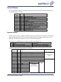
Physical Interfaces
At physical layer, there are two kinds of interfaces for command and data communication:
•
RS485 serial port
•
Ethernet
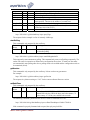
Different equipment supports different set of physical interfaces:
RS485
Ethernet
SR 400
AR 400
Support
Support
Support
MVM
Support
Logical Software Interfaces
On top of RS485 and TCP/IP socket interfaces, Matrics provides a byte stream communication
protocol (referred to as a “byte stream protocol”).
Additionally, an HTTP over TCP/IP interface is available to provide a Web-based administration
console (using HTML), and well as a service interface allowing for machine to machine interaction
(using XML). In both cases, the actions are initiated in the form of an HTTP request.
The default port for HTTP requests is port 80, and the default port for the socket interface is port
3000.
RFID Application Scenarios
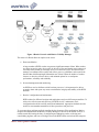
1. Reader Network Environment
A collection of RFID readers compose a logical network. Readers are not only responsible for
collecting tag data, but monitoring the RFID network devices.
Matrics API Programmer’s Manual.
3
Figure 1 Reader Network with Matrics Visibility Manager
The nature of a Reader Network implies some issues:
a. Data consolidation
A large number of RFID readers can generate significant amount of data. When readers
are acting as passive units, they need to be driven by Host and simply report whatever is
currently visible within its read range in one or several read cycles. The Host needs to
manage to coordinate all the readers and collect, process, consolidate, and reconcile the
data and then distill meaningful information out of them. When the number of readers
increase, so does the effort to achieve and maintain optimal or even adequate
performance, reliability and scalability.
b. Network management and monitoring.
As RFID are used to facilitate critical business processes, it is important to be able to
promptly detect and report any errors to maintain the integrity and stability of the RFID
network.
c. Readers’ configuration and maintenance
RFID readers for different locations and applications may have different personalities. To
achieve the effectiveness and efficiency for RFID devices’ maintenance, their
configuration should be carefully tracked and maintained. Appropriate methods are also
needed to accommodate automation of these procedures and processes.
To overcome these problems and help expedite the development of Host applications, Matrics
designed and implemented the Matrics Visibility Manager, as known as the MVM. It acts as a
central control unit bearing the duty of configuring and managing readers, collecting and
consolidating tag data, and acts as a bridge between the RFID reader network and the enterprise
Matrics API Programmer’s Manual.
4
network to logically/physically isolate two network segments to reduce the potential impact to
enterprise network. The MVM also acts as the only software interface access point for the
enterprise Host application, so that the host does not need to worry about the low-level interaction
with the reader devices.
The MVM is architected as a plug-and-play network appliance with minimum maintenance
requirement. It talks to readers and provides a simple HTTP/ XML interface for host side
applications.
Some of the MVM features, such as consolidation of tag data and event generation, HTTP and
XML data communication interfaces are also available on the AR 400 platform, so that it can
work in autonomous mode and greatly reduce the data traffic to the Host application. The
mechanism and interface for configuration and command/data communication are also kept the
same for an AR 400 and the MVM so the Host application can easily scale up and down with
minimum modification.
The MVM is optional. Users could choose to interact with RFID readers directly. And since an
AR 400 also provides the similar interface over HTTP and XML and is capable to work in self
polling mode (autonomous mode), the Host side can use the same programming model as
working with the MVM. In this case, each AR 400 is analogous to one mini-MVM controlling a
single reader.
2. Real-time Application
Sometimes a real-time response is important or the Host application may want to have direct
control of the read cycle and/or change some parameters on the fly. In these kinds of situation, the
byte stream protocol over either RS485 or Ethernet TCP socket communication would be a better
choice.
Matrics API Programmer’s Manual.
5
Section 3. XML over HTTP Host Interface
This section provides a conceptual overview of the standard methodology and model applied in the
XML over HTTP messaging mechanism. The goal of this mechanism is to provide an easy and
flexible integration programming interface, to hide complexity and hardware variations, and to make
the Host system less sensitive to changes imposed by firmware changes.
This interface is available on an MVM and an AR 400 reader. In the following discussion in this
section, we will use generic notion of device to refer to either the MVM or an AR 400 reader.
Typically, when this mode is utilized, one or more of the read points are configured using an
autonomous polling method, such as polled or periodic. As such, the collected data can be retrieved
by the host system independent of the low-level operations of the reader(s).
By default, the HTTP port on MVM and AR 400 is 80. On AR 400, this port value can be changed
through Web-based and serial administration console.
RFID Tag Information
The knowledge of an RFID tag includes: RFID Tag ID value, optional user assignable ID and
threshold rule, current RFID tag state, last RFID tag state transition (tag event), time stamp and read
point list. A Matrics device can acquire the knowledge of a RFID tag though two methods. The
conventional one is to read through a read point (antenna). The second one is through the import tag
list.
RFID Tag ID
Each RFID tag has a unique ID, which could be encoded with different standards. In the HTTP/ XML
based interface protocol, Matrics provides two different presentation formats for the same ID data:
Matrics Hexadecimal Raw Format
This format presents the raw RFID tag value in a hex decimal string. This string is a strict
presentation of the original RFID tag value without any bits being omitted. For example, a 64 bit tag
always has a length of 16 hexadecimal characters, and a 96 bit tag always has a length of 24
hexadecimal characters, no matter if leading or tailing bits are actually zeros.
This strict length requirement is mandatory for both the output tag list as in a query result, and the
input tag list as used in import tag list or purge tag list.
To get the query result in this format, the optional parameter “&raw=1” must be added to the query
string. For example:
http://192.168.0.1/cgi-bin/dataProxy?oper=queryTags&raw=1
http://192.168.0.1/cgi-bin/dataProxy?oper=queryEvents&raw=1
Matrics API Programmer’s Manual.
6
Matrics Type-Id Fields Format
Rather than use the ‘native’ encoding scheme, Matrics also provides one presentation format that is
able to handle Matrics and other EPC tag encoding schemes in one simple format.
There are two pieces of information that make a tag unique in the world: “ID” and “type.” ID can
contain up to 64 bits of information. Type is also a 64-bit value; however, the amount of information
contained within the 64 bits varies by tag type (Matrics or EPC.). Both fields are represented in hex,
minimizing the data transfer.
This is the default presentation format in the result tag list of HTTP query commands.
Optional User Assignable ID
As an optional feature, in addition to the native tag ID value, you may choose to use a more
meaningful user defined ID to identify a tag or the item a tag represents. This user defined ID is
called UID (uid). It is a plain text string with a limit length of 32 characters. For example: “Small
Shoe Box”, “SKU001”, “Part ABC”, etc.
Another advantage of the user defined ID is that it is not necessary a one-to-one relationship between
a native tag ID and a user defined ID, it may be a one-to-many relationship. In other words, for each
UID, there could be multiple native tag IDs associated with it.
For example, if you have ten computer monitors, each with a unique RFID, you can assign one UID
as “Big Brand Monitor” to all of these ten units. At the same time, you can specify a threshold value
and rule for this specific UID. So whenever the number of the items with this same UID falling below
or rising above this threshold value, a threshold tag event would be generated for this UID. This
ensures that you are notified when changes in the amount of assets occur, instead of, or in addition to,
when assets move.
The only way to specify a UID and its rule is through the import tag list, as optional attributes to the
<Tag/> XML tag. Because of the running state, the UID and its threshold rule for a group of RFID
tags can be specified only once at the first record, and all others are implied.
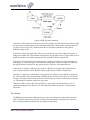
RFID Tag State and State Transition
As a tag is moving in and out of reading range, a RFID tag state changes accordingly. Figure 4 shows
different RFID states in a Matrics device and the state transitions.
Matrics API Programmer’s Manual.
7
Figure 2 RFID Tag State Transition
Transition 1: After being read for the first time, the tag changes to visible state and stays there as long
as it still can be read through any of the subordinate read points. This transition could generate New
Tag Event. If New Tag Event is disabled, then this event could be promoted to more general
Visibility Change Event.
Transition 2: After being read before, when it can not be read by any of the read points anymore, it
changes to invisible state. This transition could generate Tag Invisible Event. If Tag Invisible Event is
disabled, then this event could be promoted to more general Visibility Change Event.
Transition 3: If an already known, but not currently visible tag is read by any read points again, its
state changes to visible state again. This transition could generate Visibility Change Event. Because
the tag has already been known by the system, the New Tag Event is not applicable here.
Transition 4: A currently visible tag can be read by a different set of read points in different read
cycle. Its state remains as visible. But this change could generate Visibility Change Event.
Transition 5: sometimes, tag information can be pushed into a Matrics device through an import tag
list. This essentially injects the knowledge of RFID tags into the device before they are read for this
first time. The tags are known to the system after that, but they are still not visible to any read points
yet. This transition would not generate any tag events.
Transition 6: When a tag is removed from either by a purge tag list or through reboot cycle, its
information disappears from the device. It will start its state transition just as if it starts from the
initial state.
Time Stamp
The RFID tag state transition could generate tag events. And each tag has a time stamp associated
with it. This time stamp records the time of the last state transition that could generate a tag event.
Non event generating state transitions do not update the time stamp.
Matrics API Programmer’s Manual.
8
Read Point List
Read Point List is a comma delimited list of Read Point Ids indicating which read point(s) the RFID
tag is currently visible at. Read Point Id is the internal automatically generated unique identifier for a
read point (antenna). The Read Point Map tells the association of the Read Point Id to the read point’s
name and other attributes.
Events
A Matrics device generates several types of events: Visibility and Threshold Events that report tag
activity; and Network Status and Exception Events that report device/system activity.
Visibility Events
There are three types of Visibility Events that are generated when changes in tag visibility occur:
•
New Tag Event—A New Tag Event is a special case event that is generated when a new tag
appears for the first time. A new tag is one that has never been seen before, and has not
previously been known to the Reader. You can then commission the tag (or associate a User ID
and a threshold rule to the tag.)
This event should be processed in a timely fashion to get meaningful results. The default Notify
option is set to Immediate for this event. If you don’t want to be notified when this type of event
occurs, set the Notify option to Never, in which case the event is promoted to a generic Visibility
Changed Event.
•
Tag Not Visible Event—A Tag Not Visible Event is a special case event that is generated when
a visible tag disappears from all Read Points. For example, if a tagged item is removed from a
shelf and is out of RF range (not being seen by any Read Point), then a Tag Not Visible Event
would apply. The Event reports where the tag was located when last visible to the system.
In the normal operation, there may be cases that a tag has transient periods when it can not be
read reliably at all time in the system. To smooth out temporary conditions, the Notify option for
this event could be set to Moderated. The system then would generate an event only when the tag
has not been read for a period of time longer than the specified moderate timeout. (The system
still knows about the tag, but it is not visible to any Read Point.) If you don’t want to be notified
when this type of event occurs, set the Notify option to Never, in which case the event is
promoted to a generic Visibility Changed Event.
•
Visibility Changed Event—A Visibility Changed Event is a generic event (not as specific as a
New Tag or Tag Not Visible Event) generated any time that the visibility of a tag changes. The
visibility change may be due to the change of the set, or the number of Read Points that the RFID
tag is visible at. For example, if a tagged item moves from a shelf on aisle 2 to another shelf on
aisle 4 (visibility changes from one Read Point to another), then a Visibility Changed Event
would apply.
Note: If the Tag Not Visible Event is enabled, a disappeared tag (previously visible, but currently
not visible to any read points any more) will generate the more specific Tag Not Visible Event
Matrics API Programmer’s Manual.
9
instead. Likewise, a New Tag Event will be generated for the first visibility change when
applicable.
This event should be processed in a timely fashion to get meaningful results. The default Notify
option is set to Immediate.
Threshold Events
A Threshold Event is generated when the number of visible tags satisfies the threshold rule for this
group of tags. By default, this event’s notify option is set to Never.
To activate the threshold condition, user defined IDs and relevant threshold rules must be specified
through an import tag list. The notify option also needs be enabled to generate event notification for
this event.
In the normal operation, a tag may have transient periods when it is changing visibility in the system,
set the notify option to Moderated to smooth out temporary conditions, and generate an event only
when the tag is not experiencing a temporary moment of invisibility.
Network Status Events
Network Status Events alert you the status change of device’s managed resources. For example, if a
problem is detected, an event is generated by the device and sent without a server request.
If you want to receive Network Status Event notifications, you must subscribe to them by setting the
SNMP configuration on the Event Notifications page. If the SNMP host is not set (or is not valid), no
Network Status Events will be sent
Network Status Events are divided into two categories, ‘device’ and ‘program.’ A Device Event notes
the change in a device’s status. A Device Event is further divided into two categories, ‘user’ and
‘system.’ Both categories have an addition specification as to whether the status change is being
reported for itself or in association with a ‘parent’ device.
For example, if the ‘user’ disabled a Reader, several events would be generated. The Reader would
get a ‘user/disable’ status notification. The Read Point(s) below the Reader would get a
‘user/disable/parent’ notification. If the system detected a problem with the Reader, it would
automatically disable the device, and the matching events would be generated. These classifications
allow you to not only see the overall effect on the Reader Network, but also allow the likely
offending component to be identified. When the fault is fixed, you can ‘enable’ the device. Any
device below it that was ‘parent disabled’ is automatically brought back online.
Exception Events
Exception Events provide the same type of information available via SNMP, except via XML. An
Exception Event gives you information when a device goes off-line, polling is turned off, etc.. You
may choose this option if you don’t support SNMP, but still want to receive feedback if the
device/program changes state. XML is enabled by setting the Notify option for Exception Events to
‘Immediate’ in the Notify column on the Event Notifications page.
Matrics API Programmer’s Manual.
10
Event Notification Preferences
If you want to be notified when particular events occur, you can choose (subscribe to) the events via
the Notifications screen. You may also choose whether or not you want to receive any event
notifications at all. If the Host Notification Link is not set (or is not valid), no notifications will be
sent. If you want to receive event notifications, simply supply a valid link. The system will test the
validity by using the Test option.
To specify the event notifications that you want to receive, select the appropriate Notify option of
each event type:
•
•
•
Never—The system never generates notifications for this event type.
Immediate—The system generates notifications for this event type as soon as they are detected,
assuming they are not ‘filtered’ out.
Moderated—The system retests this condition every minute up to the timeout value. If the
condition still exists and an intervening event has not happened since, the system generates
notifications for this event type, assuming they are not ‘filtered’ out.
The type of event filters available include:
•
•
•
•
•
•
•
None—No filter. Allows all events to pass through.
Zone Inclusive—Only allow events that occur in a specific Read Point Zone to pass through.
Class Inclusive—Only allow events that occur in a specific Read Point Class to pass through.
Read Point Inclusive—Only allow events that occur in a specific Read Point to pass through.
Zone Exclusive—Only allow events that do NOT occur in a specific Read Point Zone to pass
through.
Class Exclusive—Only allow events that do NOT occur in a specific Read Point Class to pass
through.
Read Point Exclusive—Only allow events that do NOT occur in a specific Read Point to pass
through.
If the SNMP host is not set (or is not valid), no Network Status Events will be sent. You also have the
option of selecting either version 1 or version 2c SNMP messages.
Communication Models
On top of HTTP protocol, there are several approaches for getting information from a device:
Query Model
A pure query model allows a device to run as an independent, isolated system in passive mode, and
does not initiate communication to the Host. The Host system can initiate HTTP queries at any time
to the device to gather runtime information. From HTTP protocol’s perspective, the Host system is
only a client, and the device is only a server.
Assuming the device’s IP address is 192.168.0.100, the following is an example of what the URL
might look like:
http://192.168.0.100/cgi-bin/dataProxy?oper=queryTags
Matrics API Programmer’s Manual.
11
The result of a ‘queryTags’ operation is an XML tag list document. As described in the definition of
tag list, there could be a ReadPointMap in the response. For efficiency, the host system should only
request the ReadPointMap once, when it first comes online. Adding ‘&map=1’ to the URL forces the
map to be sent with the query. Without this option, the map is only sent when it has been changed.
Thus, for subsequent queries, it is not necessary or efficient to explicitly request the map every time.
Two kinds of information can be reported by a Matrics device: a snapshot view of the world and a
delta view of accumulated changes.
The snapshot view can be acquired by the “queryTags” command. By default, this is a snapshot of all
the tags currently visible by any subordinate read points. Any tags that are not visible by any read
points at the moment of the query are not included in the report. So this is a partial view of the whole
world.
The complete snapshot view can also be got by the “queryTags” command, but must be with the
optional parameter “&invis=1” in the query string. This returns a tag list including all the tags this
device has ever had knowledge of, except those that have been purged. All visible tags have a nonempty Read Point List; this may be implied by the running state.
The delta view is a tag event list as the result of the “queryEvents” command. It accumulates all the
events and associated tag information since last time this command has been run. It tells all the delta
changes, instead of snapshot since then. The Host system can apply these changes to its original
snapshot to get an updated view.
Subscribe/Notify Model
This model allows a device to notify the Host system as event occurs, in the form of an HTTP query
request. In this case, the Host system is an HTTP server, and the Matrics device is an HTTP client.
Upon notification, the Host should come back to query the device. The result is an event list XML
document that contains all the ‘events’ that have occurred since last event query. In this case, the Host
is an HTTP client, and the device is an HTTP server.
The Host system can also specify (subscribe) for the type of event, and the conditions under which it
wants to receive notification. This allows the Host to see changes as they happen, and only the
‘changes’ are communicated.
When the subscribe/Notify model is used (or a hybrid), communication is typically initiated by the
Reader. In order to use this model, you must supply a host IP address (and port, if it is not the default
80) where the host system can be contacted (via HTTP query) and notified of pending events. There
are two options you must support: test and notify. The following are examples of what the host URL
might look like:
http: //192.168.0.127/?oper=test
http: //192.168.0.127/?oper=notify
The Reader uses the ‘test’ option to validate the link to the host system. The host system should reply
with a simple XML acknowledgement described in the XML section of this document.
The Reader uses the ‘notify’ option to notify the host system that one or more events are available for
query (i.e., something has changed since the last query.) The host system should reply with a simple
Matrics API Programmer’s Manual.
12
XML acknowledgement described in the XML section of this document. Additionally, the host
system can send Tag List data (Import Tag List or Purge List) as part of the reply. A Tag List reply is
purely optional.
The user can ‘import’ tags, optionally along with the uid and rule, into the system,at any time, as part
of a notify reply. Note that tags that are ‘imported’ prior to their first physical visibility (being seen
by the Reader at a Read Point) will never report a New Tag Event, but will simply report a Visibility
Changed Event when the physical tag appears at a Read Point.
After the host system receives the notification and acknowledges it, it should follow up with a
‘queryEvents.’ The following is an example of what the URL might look like:
http://192.168.0.100/cgi-bin/dataProxy?oper=queryEvents&map=1
The result of a ‘queryEvents’ operation is an XML document containing information about the events
that have occurred since the last query. This allows you to keep a running view of the changes in asset
visibility.
Note: For efficiency, the ReadPointMap (the ‘map’ which associates Read Point IDs, Read Point
Names, Class and Zone information for your Read Point locations) should only be requested once,
when the host system first comes online. Adding ‘map=1’ to the URL forces the map to be sent with
the query. When it is not added, the map is only sent when it has possibly changed. Thus, for
subsequent queries, it is not necessary or efficient to request the map each time.
Hybrid Model
The typical (and most efficient) approach is a hybrid of the two. For example, you query the ‘tags’ of
the system to get a snapshot of what is visible, and then subsequently wait for notifications. Upon
notification, you can query the ‘events’ of the system, which is essentially delta information, and then
update your view by applying the delta to the original one.
HTTP Protocol Support
HTTP URL and Query String
The “http” scheme is used to locate network resources via the HTTP protocol. This is the schemespecific syntax and semantics for http URLs:
http_URL = “http:” “//” host [ “:” port] [abs_path [ “?” query ] ]
If the port is empty or not given, port 80 is assumed. The semantics are that the identified resource is
located at the server listening for TCP connections on that port of that host, and the Request-URI for
the resource is abs_path. If the abs_path is not present in the URL, a “/” is placed as the Request-URI
in the HTTP request start-line.
Matrics API Programmer’s Manual.
13
The URL scheme allows you to include a query string that is to be passed to the designated URL.
This is indicated by placing a question mark at the end of the URL, followed by the desired query
string. For example:
http://www.host.com/cgi-bin/proxyProgram?query_string
And the query_string could be:
name=value&name=value&name=value
The query string consists of multiple name/value parameter pairs with an "&" in between each pair.
The designated URL, usually a CGI or proxy program, then could parse and interpret this query string
and take appropriate actions.
Web browsers, such as MS Internet Explorer, Netscape Navigator, Mozilla, etc. are typical HTTP
clients. http_URL is used as internet address, and displayed in the address bar in these programs. Web
browsers parse the http_URL, convert it into a HTTP GET request message and send to the server,
then receive and handle (display) the response. Basically, a web browser can readily be used as a test
tool to send simple query to an HTTP server, simply by attaching the query string at the end of the
internet address.
Matrics HTTP Service Interfaces
Matrics platform provides four logical service interfaces in the form of HTTP Request-URI, and serve
as command proxies.
/cgi-bin/loginProxy
This serves as the user login command proxy for the Web-based administration
console
/cgi-bin/coreProxy
This serves as the command proxy for the back-end core server
/cgi-bin/dataProxy
This serves as the main data communication interface interacting with the Host
Commands and their respective parameters are passed to these interfaces as a query string in the http
URL. we call these as HTTP query commands in the context of this discussion. The general format of
these commands looks like:
http://192.168.0.1/cgi-bin/dataProxy?oper=<command>¶m1=val1¶m2=val2…
In the query string, a special name(“oper”)/value pair is used to tell the name of the command.
Parameters for this specific command are defined by the following name/value pairs.
You can always try these command samples via a Web browser. Simply copy
the URL into a Web browser’s address bar, and replace the IP address as
appropriate.
Matrics API Programmer’s Manual.
14
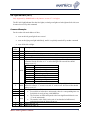
Matrics HTTP Query Commands
Following provides the definition of HTTP query commands and their parameters:
login
This command is only accepted by the loginProxy.
Parameter Type Default Meaning
Name
name
string N/A
The user name used to login the Web-based administration console
pswd
string N/A
The password for this user name
For example:
http://192.168.0.1/cgi-bin/loginProxy?oper=login&name=user&pswd=password
The response for this command is a HTML <META> element with a redirection.
1. If the command succeeds, the response is:
<META HTTP-EQUIV="Refresh" CONTENT="0; URL=/cgi-bin/mainPage">
2. If either the user name or the password is wrong, the response is:
<META HTTP-EQUIV="Refresh" CONTENT="0; URL=/cgi-bin/loginPage?err=17">
3. If there is already another user currently logged in, the response is:
<META HTTP-EQUIV="Refresh" CONTENT="0; URL=/cgi-bin/loginPage?err=62">
4. If the password for this user has not been changed from the reset password, the response is:
<META HTTP-EQUIV="Refresh" CONTENT="0; URL=/cgibin/passwordPage?user=user&reset=1">
queryEvents
This command is only accepted by the dataProxy.
Parameter Type Default Meaning
Name
map
int
0
=1, send read point map in the query result
raw
int
0
=1, send tag data in raw format
For example:
http://192.168.0.1/cgi-bin/dataProxy?oper=queryEvents
This returns a list of current tag events.
queryTags
This is command is only accepted by the dataProxy.
Parameter
Type Default Meaning
Name
Matrics API Programmer’s Manual.
15
map
invis
raw
uidOnly
since
int
int
int
int
hex
0
0
0
0
0
showLastRP int
ascTime
int
0
0
sendRule
int
For example:
0
=1, send read point map in the query result
=1, send currently invisible tags too
=1, send tag data in raw format
=1, send only those tags which have user ids
>0, send only tags whose visibility has been changed since the
time specified. The time is the number of seconds since
=1, show the last read point this tag has been seen
=1, show text timestamp in ANSI C’s asctime() format
(“Thu Jan 01 00:12:40 1970”)
=1, send the rule associated with one user id
http://192.168.0.1/cgi-bin/dataProxy?oper=queryTags
The response for the example is a list of currently visible tags.
startPolling
This command is only accepted by the coreProxy.
Parameter Type Default
Meaning
Name
onOff
int
0
=1, enable polling
=0, disable polling
For example:
http://192.168.0.1/cgi-bin/coreProxy?oper=startPolling&onOff=1
This temporarily starts autonomous polling. This command only turns on/off polling temporarily. The
reader will restore its operation as defined in its configuration after reboot. To make sure the reader
can automatically start polling after reboot, polling needs to be enabled and the configuration needs to
be committed (saved).
getVersion
This command is only accepted by the coreProxy. It does not have any parameters.
For example:
http://192.168.0.1/cgi-bin/coreProxy?oper=getVersion
The response is a plain text string as “3.4.5” for the current software/firmware version.
setDateTime
This command is only accepted by the coreProxy.
Parameter Type Default
Meaning
Name
input
string N/A
In the form of “MMDDHHmmCCYY.SS”, where MM is the
month, DD is the day, HH is the hour, mm is the minute, CC
is the century, YY is the year, and SS is the seconds.
The following command synchronizes the device’s clock to 12/04/2002 16:17:10:
http://192.168.0.100/cgi-bin/dataProxy?oper=setDateTime&input=120416172002.10
If the command is properly formatted and accepted, the reply may look like:
Matrics API Programmer’s Manual.
16
<Matrics>
<Error code='0' msg='Wed Dec 4 16:17:10 EST 2002'/>
</Matrics>
If not properly formatted or accepted, the error code and message will reflect the nature of the
problem.
processTagList
This command is only accepted by the dataProxy.
Parameter Type Default
Meaning
Name
url
string Host link
The URL of the tag list
The following command can be used to initiate an RFID tag list import or purge (even when not using
the event model):
http://192.168.0.100/cgi-bin/dataProxy?oper=processTagList&url=http://129.168.0.101/
hostTagList.xml
The URL argument is optional. If not present, the command will attempt to use the host notification
link. If successful, the reply may look like:
<Matrics>
<Error code='3008' msg='Operation was successful'/>
</Matrics>
This means that the system has successfully enqueued an operation to access the host (system pointed
at by the URL) to process a tag list for import and/or purge list. When contacting the host system, we
will include the following on the URL:
?oper=process
The host system should return the XML described in the XML File Descriptions section of this
manual.
If not properly formatted or accepted, the error code and message will reflect the nature of the
problem.
setLightIndicator
This is command is only accepted by the dataProxy.
Parameter Type Default Meaning
Name
rred
string N/A
Right Red Light. “on”/“off” turns on/off the red light on the right
side
rrto
int
0
Right Red Light Timeout, a 16 bit integer that represents a decimal
number in 100s of milliseconds for which the light will be on. If
parameter is omitted or set to zero, light is turned on indefinitely.
rgreen
string N/A
Right Green Light. “on”/“off” turns on/off the green light on the
right side
Matrics API Programmer’s Manual.
17
rgto
lred
lrto
lgreen
int
string
int
string
lgto
int
For example:
0
N/A
0
N/A
0
Right Green Light Timeout, same definition as the “rrto”above
Left Red Light. “on”/“off” turns on/off the red light on the left side
Left Red Light Timeout, same definition as the “rrto”above
Left Green Light. “on”/“off” turns on/off the green light on the left
side
Left Green Light Timeout, same definition as the “rrto”above
To turn the right red light on indefinitely and the left green light on for 1 second
http://192.168.0.100/cgi-bin/dataProxy?oper=setLightIndicator&rred=on&rrto=0&lgreen=on&
lgto=10
The same can be accomplished with (no rrto needed):
http:// 192.168.0.100/cgi-bin/dataProxy?oper=setLightIndicator&rred=on&lgreen=on&lgto=10
To turn off the right red light:
http:// 192.168.0.100/cgi-bin/dataProxy?oper=setLightIndicator&rred=off
Event notification
These are HTTP query commands sent by device to the Host as event notification.
1. test
For example:
http: //192.168.0.127/?oper=test
This is the test command sent by the device to verify the host notification link specified is alive
and working. This command is used whenever the host notification link is changed. The Host
should respond with a minimum host acknowledgement to honor this test. Otherwise, the host
notification link will not be accepted.
2. notify
For example:
http: //192.168.0.127/?oper=notify
This is the real event notification command the Host will receive at runtime. As for the notify
command, the Host needs to respond with a minimum host acknowledgement. The host can also
embed other information such as import tag list in the acknowledgement, so it does not need to
initiate another separate transaction to pass this information through.
HTTP Support on the Host Side
The HTTP technology of choice is up to the user discretion. It can range form a full feature server to a
simple HTTP listener.
XML Document Descriptions
This section describes the definition of the fields in the XML documents. All items are mandatory
unless otherwise stated. Any extra field that may appear now or in the future should be ignored.
Matrics API Programmer’s Manual.
18
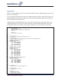
All well-formed Matrics XML documents have the following basic structure:
1
2
3
4
<?xml version=’1.0’?>
<Matrics> <!—- start-tag of Matrics XML document -->
<!—- other document elements -->
</Matrics> <!—- end-tag of Matrics XML document -->
The start tag <Matrics> and end tag </Matrics> must be present to form the root element of a Matrics
XML document. All following element tags must reside inside the content of this element.
All comments in the XML document samples are for explanatory purpose in this document only.
They are not present in the real runtime communication documents.
Running State
Information for certain attribute fields in the XML files is communicated in ‘running state.’ This is a
method whereby an attribute only needs to be sent when it is different from the preceding value of that
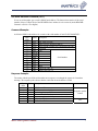
field. The result is a significant reduction in file size and network bandwidth use.
Example:
1
2
3
4
5
6
7
8
9
10
11
<?xml version=’1.0’?>
<Matrics> <!—- start-tag of Matrics XML document -->
<TagList> <!—- start-tag of a tag list -->
<Tag raw=‘8900640246000000’ uid=‘SKU789’ />
<Tag raw=‘8900640246000001’ />
<Tag raw=‘8900640246000002’ uid=‘‘ />
<Tag raw=‘8900640246000003’ />
<Tag raw=‘8900640246000004’ uid=‘SKU980’ />
<Tag raw=‘8900640246000005’ />
</tagList> <!—- end-tag of a tag list -->
</Matrics> <!—- end-tag of Matrics XML document -->
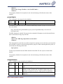
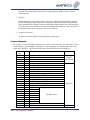
The following table illustrates the information carried by the above example:
No. RFID Tag Value
Uid
Comment
1
8900640246000000
SKU789 uid is explicitly specified as SKU789
2
8900640246000001
SKU789 uid is implied as SKU789 because of running state
3
8900640246000002
No uid because it is explicitly cleared
4
8900640246000003
No uid because of running state
5
8900640246000004
SKU980 uid is explicitly specified as a new value of SKU980
6
8900640246000005
SKU980 uid is implied as SKU980 because of running state
Minimal Host Acknowledgement
<HostAck/> is an empty-element tag denoting Host’s acknowledgement of test or notification. This tag is
mandatory if there is no tag list embedded in the acknowledgement response, is optional if a tag list is
present.
For example, this is the minimum Host acknowledgement:
1
2
3
4
<?xml version=’1.0’?>
<Matrics> <!—- start-tag of Matrics XML document -->
<HostAck /> <!—- minimum Host acknowledgement tag -->
</Matrics> <!—- end-tag of Matrics XML document -->
RFID Tag List
A tag list is a logical container holding a list of RFID tags. Each RFID tag is uniquely identified by its tag
value, and may have some other attributes associated with it. A tag list could be the result in the response
of a query for tags command, or as a source for the Host to inject the knowledge for some tags into a
Matrics API Programmer’s Manual.
19
device. The Host can use a purge list to remove the knowledge of tags from a device. A tag list as an
import list has different semantics than a tag list as the result of a query command, hence they have
different set of attributes fir the <tag/> XML tag.
<TagList> is start XML tag for a tag list.
</TagList> is end XML tag for a tag list.
<PurgeList> is start XML tag for a purge list.
</PurgeList> is end XML tag for a purge list.
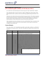
<Tag/> is empty-element tag for a single tag entry in the content of a tag list or purge list. It has
following attributes when it is used in an import tag list:
Attribute Type
Default Meaning
name
id
Hex
N/A
The id field of the RFID tag value
type
Hex
Runnin The type field of the RFID tag value
g state
raw
Hex
N/A
Raw tag id value. Always a 16 character hexadecimal value for a 64
bit tag; a 24 character hexadecimal value for a 96 bit tag.
uid
String
Runnin Optional user assignable ID value
g state
rule
String
Runnin This optional rule describes a threshold event rule for a specific uid.
g state
Only one rule should be present for a given uid, otherwise last one
wins. The format of the rule is a string consisting of two operation
characters as operators and a 32 bit binary value other than 0 in
decimal format. The definition of these operators are:
Operators
Meaning
Example
LT (default) Less Than
“100” is the same as “LT100”
GT
Greater Than “GT50”
When <tag/> is used in a purge list, only the attributes ‘id’ and ‘type’ or ‘raw’ is used; attributes uid and
rule are not applicable and will be ignored.
In this example, the <HostAck/> tag is omitted because of the presence of an import tag list:
1
2
3
4
5
6
7
<?xml version=’1.0’?>
<Matrics> <!—- start-tag of Matrics XML document -->
<TagList> <!—- start tag for tag list -->
<tag raw=‘206980C00021260459800000’ uid=‘34 inch digital TV’ rule=‘100’ />
<tag raw=‘8900640246000000’ uid=‘stereo system’ rule=‘30’ />
</TagList> <!—- end tag for tag list -->
</Matrics> <!—- end-tag of Matrics XML document -->
In this example, the <HostAck/> tag is omitted because of the presence of a purge tag list:
1
2
3
4
5
6
7
<?xml version=’1.0’?>
<Matrics> <!—- start-tag of Matrics XML document -->
<PurgeList> <!—- start tag for purge list -->
<tag raw=‘206980C00021260459800000’ /> <!—- a 96 bit RFID tag -->
<tag raw=‘8900640246000000’ />
<!—- a 64 bit RFID tag -->
</PurgeList> <!—- end tag for purge list -->
</Matrics> <!—- end-tag of Matrics XML document -->
Matrics API Programmer’s Manual.
20
RFID Tag List Query Result
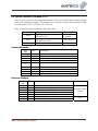
A tag list can be returned as the result of a queryTags command. The same <tag/> XML tag is used to
describe an entry in this tag list, but it has some additional attributes for this specific situation:
Attribute Type
Default Meaning
name
time
Hex
Runnin The time stamp indicating when this tag has been seen. It is a
g state
hexadecimal value representing the number of seconds since the
Epoch (Jan. 1, 1970.)
RPL
string
Runnin Read Point List. This is a comma delimited list of ReadPointIds
g state
(from the map) indicating which read point(s) the RFID tag is
currently visible at.
Read Point Map
Logically, each antenna is called a Read Point, and identified internally by an automatically generated
unique Read Point ID. Through the Web-based administration console, a user can configure a read point
with name, read point class, read point zone, and other attributes. Please refer to the user manual for detail
instruction.
To be efficient, only the Read Point ID, instead of the name, is used to identify an antenna in a tag list or
event list. The Read Point Map is where you can find out its associated information. It is a logical
container holding the association of a Read Point ID to its name, and the Read Point Class and Read Point
Zone it uses.
Read Point Map can be sent as part of the response of a query, but does not need to be sent every time. It
is always sent automatically in the response of the very first query after power on or reboot, or whenever
the read point configuration has been changed. All other time, it is only sent when it is explicitly asked in
the query.
If the Host system needs to know the detail configuration of each read point, it should explicitly ask for
the Read Point Map at its very first query to make sure it has the correct association information. In order
to keep its record consistent with the information in the device, it still needs to monitor and detect the
Read Point Map in the response of each query, even it has not explicitly asked for it, and update its own
record promptly.
<ReadPointMap> is start XML tag for a ReadPointMap list.
</ReadPointMap> is end XML tag for a ReadPointMap list.
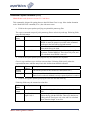
<Pair/> is empty-element tag for a single entry in the content of a Read Point Map list. It has following
attributes:
Attribute Type
Default Meaning
name
name
String
N/A
The name of the read point
id
Decimal N/A
The unique id of the read point
zone
String
Runnin The name of the Read Point Zone used by this read point
g state
class
String
Runnin The name of the Read Point Class used by this read point
g state
Matrics API Programmer’s Manual.
21
For example:
1
2
3
4
5
6
7
8
9
10
11
12
13
14
15
16
17
18
<?xml version=’1.0’?>
<Matrics> <!—- start-tag of Matrics XML document -->
<EventGroup> <!—- start-tag of an event group -->
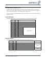
<ReadPointMap> <!—- start tag for a Read Point Map -->
<pair name=‘Read Point #1’ id=‘231’ zone=‘First Door’ class=‘Portal’ />
<pair name=‘Read Point #2’ id=‘16’ />
<!-- running state determines the zone and class -->
<pair name=‘Read Point #3’ id=‘790’ zone=‘Second Door’ />
<!-- a new zone, running state determines the class -->
<pair name=‘Read Point #4’ id=‘68’ />
<!-- running state determines the zone and class -->
</ReadPointMap> <!—- end tag for a Read Point Map -->
<tagList> <!—- start tag for purge list -->
<tag raw=‘206980C00021260459800000’ time=‘111111111’ RPL=‘1,2,3’ />
<tag raw=‘8900640246000000’ />
<!—- running state -->
</tagList> <!—- end tag for purge list -->
</EventGroup> <!—- end-tag of an event group -->
</Matrics> <!—- end-tag of Matrics XML document -->
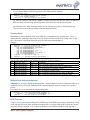
The Read Point Map in the above example carries the following information:
Read Point name Read Point ID Read Point Zone Read Point Class
Read Point #1
231
First Door
Portal
Read Point #2
16
First Door
Portal
Read Point #3
790
Second Door
Portal
Read Point #4
68
Second Door
Portal
Event Query Result
Similar to a tag list, an event list is returned as a response for the query for events.
<EventList> is start XML tag for a list of events.
</EventList> is end XML tag for a list of events.
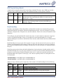
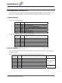
Every entry in the event list is also described by the <Tag/> XML tag with one extra attribute:
Attribute Type
Default Meaning
name
event
Decimal Runnin The type number of event associated with this RFID tag. Legitimate
g state
event values are:
0 New Tag
1 Tag Not Visible
2 Tag Visibility
Changed
3 Threshold Event
If the Exception event is enabled, an exception list is also returned as a response for the query for events.
<ExceptionList> is start XML tag for a list of exception events.
</ExceptionList> is end XML tag for a list of exception events.
<Exception/> is the empty-element tag for a single entry in the content of an exception list. It has
following attributes:
Attribute Type
Default Meaning
name
Matrics API Programmer’s Manual.
22
time
Hex
name
String
state
type
reason
Runnin
g state
Runnin
g state
Decimal Runnin
g state
Decimal Runnin
g state
String
N/A
The time stamp indicating when this exception occured. It is a
hexadecimal value representing the number of seconds since the
Epoch (Jan. 1, 1970.)
The name of the device generating this event
The current status of the device
The type of the device
The reason for the exception
These attributes are actually the same as defined for SNMP events. Please refer to the SNMP description
for details.
Sample event list:
1
2
3
4
5
6
7
8
9
10
11
12
13
14
15
16
17
18
19
20
21
22
23
24
25
26
27
28
<?xml version=’1.0’?>
<Matrics> <!—- start-tag of Matrics XML document -->
<EventGroup> <!—- start-tag of an event group -->
<ReadPointMap> <!—- start tag for a Read Point Map -->
<pair name=‘Read Point #1’ id=‘231’ zone=‘First Door’ class=‘Portal’ />
<pair name=‘Read Point #2’ id=‘16’ />
<pair name=‘Read Point #3’ id=‘790’ zone=‘Second Door’ />
<pair name=‘Read Point #4’ id=‘68’ />
</ReadPointMap> <!—- end tag for a Read Point Map -->
<EventList> <!—- start tag for purge list -->
<tag event=‘0’ raw=‘206980C00021260459800000’ time=‘4104fec8’ RPL=‘1,2,3’ />
<tag raw=‘8900640246000000’ />
<!—- running state -->
<tag event=‘1’ raw=‘206980C00021260459800001’ time=‘4104feba’ RPL=‘‘ />
<tag event=‘2’ raw=‘206980C00021260459800002’ time=‘4104febf’ RPL=‘2,3’ />
</EventList> <!—- end tag for purge list -->
<ExceptionList>
<Exception time='4104fb58' name='Read Point 1-1-1-2-1' state='0' type='0' reason='Enable
all'/>
<Exception state='1' reason='No antenna'/>
<Exception time='4104fb94' state='0' reason='Enable all'/>
<Exception state='1' reason='No antenna'/>
<Exception time='4104fbd0' state='0' reason='Enable all'/>
<Exception state='1' reason='No antenna'/>
<Exception time='4104fc0c' state='0' reason='Enable all'/>
<Exception state='1' reason='No antenna'/>
<Exception time='4104fc23' name='Core Server Polling' state='0' type='1' reason='Matrics
MVM Core Server starts polling'/>
</ExceptionList>
</EventGroup> <!—- end-tag of an event group -->
</Matrics> <!—- end-tag of Matrics XML document -->
Error Result
<Error /> is empty-element XML tag denoting a system error.
It has following attributes:
Attribute Type
Default
name
Code
decimal N/A
Msg
string
N/A
Meaning
System error code
human readable description of the error
For example:
1
2
3
4
<?xml version=’1.0’?>
<Matrics> <!—- start-tag of Matrics XML document -->
<Error code=‘99’ msg=‘An error description goes here’ />
</Matrics> <!—- end-tag of Matrics XML document -->
Matrics API Programmer’s Manual.
23
Sample DTD
Below is a sample DTD that you can use to describe the XML elements in XML Declaration Syntax. This
just serves as a reference.
It is not required for either the Host system or the Matrics platform to input or output a DTD. However, if
you use an XML parser that desires a DTD, you can use the description below (make sure you insert the
DOCTYPE entry into the input stream.)
Validating parsers read the DTD before they read your document so that they can identify where every
element type ought to be and how they relate to each other, so that applications that need to know this
information in advance (most editors, search engines, databases, etc.) can set themselves up properly.
1
2
3
4
5
6
7
8
9
10
11
12
13
14
15
16
17
18
19
20
21
22
23
24
25
26
27
28
29
30
31
32
33
34
35
36
37
38
39
40
41
42
43
44
45
46
47
48
49
50
51
52
53
54
55
56
<!-Typical usage:
<?xml version=‘1.0’?>
<!DOCTYPE Matrics SYSTEM ‘MatricsXML.dtd’>
<Matrics>
...
</Matrics>
DTD for Matrics User XML
-->
<!-- Top Level -->
<!ELEMENT Matrics (EventGroup|HostAck|Error)*>
<!-- EventGroup -->
<!ELEMENT EventGroup (ReadPointMap|TagList|EventList|ExceptionList)*>
<!ELEMENT ReadPointMap (Pair)*>
<!ELEMENT Pair EMPTY>
<!ATTLIST Pair
name CDATA #REQUIRED
id
CDATA #REQUIRED
zone CDATA #IMPLIED
class CDATA #IMPLIED
>
<!ELEMENT EventList (Tag)*>
<!ELEMENT TagList (Tag)*>
<!ELEMENT Tag EMPTY>
<!ATTLIST Tag
raw
CDATA #REQUIRED
id
CDATA #IMPLIED
uid
CDATA #IMPLIED
type CDATA #IMPLIED
event CDATA #IMPLIED
time CDATA #IMPLIED
RPL
CDATA #IMPLIED
rule CDATA #IMPLIED
>
<!ELEMENT ExceptionList (Exception)*>
<!ELEMENT Exception EMPTY>
<!ATTLIST Exception
reason CDATA #REQUIRED
time
CDATA #IMPLIED
name
CDATA #IMPLIED
type
CDATA #IMPLIED
state CDATA #IMPLIED
>
<!-- HostAck -->
<!ELEMENT HostAck (TagList|PurgeList)*>
<!-- PurgeList -->
<!ELEMENT PurgeList (Tag)*>
<!-- Error -->
<!ELEMENT Error EMPTY>
<!ATTLIST Error
code CDATA #REQUIRED
Matrics API Programmer’s Manual.
24
57
58
msg
CDATA #REQUIRED
>
Matrics API Programmer’s Manual.
25
Section 4. SNMP Trap
A Matrics device’s Statistics and Traps Management Information Base (MIB) is defined in the
“Matrics-snmp.mib” file. These objects are part of the enterprise MIB for Matrics.
Enterprise Identifier
The enterprise identifier for “Matrics Inc.” is 12405.
matrics
matricsMvm
matricsMvmTrap
OBJECT IDENTIFIER ::= { enterprises 12405 }
OBJECT IDENTIFIER ::= { matrics 1 }
OBJECT IDENTIFIER ::= { matricsMvm 1 }
devEvent trap
The “devEvent” trap is defined in the MIB. This trap is generated to indicate that a device event has
occurred.
The trap’s Object ID:
(.iso.org.dod.internet.snmpV2.snmpModules.snmpMIB.snmpMIBObjects.
snmpTrap.snmpTrapOID.0) = OID: enterprises.12405.1.1.0.1
This trap has 4 variable bindings:
1. Name:
OID:
Syntax:
Access:
Status:
Description:
trapDevName
enterprises.12405.1.1.1 { matricsMvmTrap 1 }
DisplayString
read-only
current
Name of the device that causes the trap.
2. Name:
OID:
Syntax:
Access:
Status:
Description:
trapDevStatus
enterprises.12405.1.1.2 { matricsMvmTrap 2 }
INTEGER
read-only
current
Current status of the device.
It could be:
enabled(0),
sysDisabled(1),
userEnabled(2),
userDisabled(3),
parentSysEnabled(4)
parentSysDisabled(5)
parentUserEnabled(6)
parentUserDisabled(7)
Matrics API Programmer’s Manual.
26
3. Name:
OID:
Syntax:
Access:
Status:
Description:
trapDevType
enterprises.12405.1.1.3 { matricsMvmTrap 3 }
INTEGER
read-only
current
Type of module that causes the trap.
It could be:
device(0),
program(1)
4. Name:
OID:
Syntax:
Description:
trapDevReason
enterprises.12405.1.1.4 { matricsMvmTrap 4 }
Display String
Reason for the trap.
Example trap (SNMP Version 1):
2002-05-15 15:55:28 Agent [192.168.0.181] (via localhost [127.0.0.1]) TRAP, SNMP v1, community public
enterprises.matrics Enterprise Specific Trap (0) Uptime: 2 days, 6:15:59.47
enterprises.matrics.matricsMvm.matricsMvmTrap.trapDevName = “Converter #3”
enterprises.matrics.matricsMvm.matricsMvmTrap.trapDevStatus = userDisabled(3)
enterprises.matrics.matricsMvm.matricsMvmTrap.trapDevType = device(0)
enterprises.matrics.matricsMvm.matricsMvmTrap.trapDevReason = “User disabled”
Example trap (SNMP Version 2c):
2002-05-15 15:58:18 Agent [127.0.0.1]:
system.sysUpTime.0 = Timeticks: (19552896) 2 days, 6:18:48.96
.iso.org.dod.internet.6.3.1.1.4.1.0 = OID: enterprises.matrics.matricsMvm.matricsMvmTrap.
matricsMvmTrap#.devEvent
enterprises.matrics.matricsMvm.matricsMvmTrap.trapDevName.0 = “Converter #3”
enterprises.matrics.matricsMvm.matricsMvmTrap.trapDevStatus.0 = userEnabled(2)
enterprises.matrics.matricsMvm.matricsMvmTrap.trapDevType.0 = device(0)
enterprises.matrics.matricsMvm.matricsMvmTrap.trapDevReason.0 = “User enabled”
Heartbeat SNMP Event
The Reader sends a “heartbeat” once a minute via SNMP (if SNMP is enabled.) This message has the
following values:
Name:
Type:
Status:
Description:
Core Server
Program
enable
Heartbeat
Matrics API Programmer’s Manual.
27
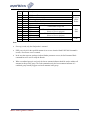
SNMP Traps
Below is a list of traps that you might receive from a Matrics Reader (and the name, status and type of
device where the trap originated), and their possible causes.
1. Message:
Device name:
Device status:
Device type:
Cause:
“Bad/missing reply from hostlink”
“HostProxy”
enabled (0)
program (1)
Bad reply is detected when you try to access the host link.
2. Message:
Device name:
Device status:
Device type:
Cause:
Alert error message “A-xxxxx”
“Logger”
enabled (0)
program (1)
Possible reasons for alert are:
“Invalid rule operator xxxx”: Incorrect operator is detected in the rule
when importing a tag to the database (imported by tagList.)
“Invalid rule xxxx”: Invalid rule is detected when importing a tag to the
database (imported by tagList.)
“No host link set”: The host link has not been specified yet when trying
to notify the host.
“Invalid XML config file in initReaderNetwork”: The XML config file is
not valid when the core server initiates the Reader network.
3. Message:
Device name:
Device status:
Device type:
Cause:
Critical error message “C-xxxxx”
“Logger”
enabled (0)
program (1)
Possible reasons for critical error message are:
“Failed to connect”: Cgi proxy cannot connect to the appropriate server.
“Open failed errno=xx”: Server cannot open the network port to listen to.
“Accept failed”: Server cannot correctly accept data from the network
port to which it’s listening.
“Bind failed”: Server cannot find the right command and parameter
combination specified in the incoming command string.
“Server transmit failed”: Server cannot send response back to cgi proxy.
“xxxx not open”: Failed to open the database xxxx.
“Can’t open pipe in notifyHost”: Core server cannot communicate with
the host link.
“No local hosts access”: Cannot add local host to trusted hosts database.
“Socket failed”: Network operation failed to open a socket.
“Listener socket failed to set SO_LINGER”: Network operation cannot
set the SO_LINGER attribute to the listener socket.
“Listener socket failed to set SO_REUSEADDR”: Network operation
cannot set the SO_REUSEADDR attribute to the listener socket.
“Giving up socket binding”: Network operation cannot bind the socket.
“Listen failed”: Network operation cannot listen to a socket.
Matrics API Programmer’s Manual.
28
“Can not open pipe”: Server can’t open communication pipe to cgi
proxy.
“map db open failed”: Can’t open the map database.
“useridx db open failed”: Can’t open the useridx database.
“TAG.DB not open”: Can’t open the TAG.DB database.
4. Message:
Device name:
Device status:
Device type:
Cause:
“Failed to read configuration file”
“Console Server”/ “Core Server”
enabled (0)
program (1)
Notification about Matrics Server failed to read in configuration file.
5. Message:
Device name:
Device status:
Device type:
Cause:
“Matrics Console Server starts running”
“Console Server”
enabled (0)
program (1)
Notification about Matrics Console Server starts running.
6. Message:
Device name:
Device status:
Device type:
Cause:
“Matrics Console Server quits running”
“Console Server”
userDisabled (3)
program (1)
Notification about Matrics Console Server quits running.
7. Message:
Device name:
Device status:
Device type:
Cause:
“Matrics Core Server starts running”
“Core Server”
enabled (0)
program (1)
Notification about Matrics Core Server starts running.
8. Message:
Device name:
Device status:
Device type:
Cause:
“Matrics Core Server quits running”
“Core Server”
userDisabled (3)
program (1)
Notification about Matrics Core Server quits running.
9. Message:
Device name:
Device status:
Device type:
Cause:
“Matrics Core Server starts polling”
“Core Server Polling”
enabled (0)
program (1)
Notification about Matrics Core Server starts polling.
10. Message:
Device name:
Device status:
Device type:
Cause:
“Matrics Core Server stops polling”
“Core Server Polling”
userDisabled (3)
program (1)
Notification about Matrics Core Server stops polling.
Matrics API Programmer’s Manual.
29
11. Message:
Device name:
Device status:
Device type:
Cause:
Reader network device’s status has been changed
The name of the device (converter/converter port reader/reader/reader
port)
enabled (0) / sysDisabled (1) / userEnabled (2) / userDisabled (3)
/ parentSysEnabled (4) / parentSysDisabled (5) / parentUserEnabled (6)
/ parentUserDisabled (7)
device (0)
Detailed reason for device’s status change:
“Initial state”: The device’s initial status is not enabled when initializing
a Reader network.
“Enable All”: The device is enabled by the “enable all” user command.
“User enabled”: The device is enabled by user.
“User disabled”: The device is disabled by user.
“Can’t establish connection to port”: The converter is disabled by error
because the server cannot establish connection to the port.
“Failed receive from reader (xxx)”: The Reader is disabled by error
because the server cannot receive from the Reader.
Matrics API Programmer’s Manual.
30
Section 5. Byte Stream Protocol
Overview
This section provides the definition of fields and behavior of the Byte Stream protocol. This protocol
can be carried on both a 4-wire RS485 link (for AR 400 and SR400) and a TCP/IP socket connection
(for AR 400 only). The default configuration for the RS485 serial link is at 230400 baud rate, with 8
data bits, 1 start bit, 1 stop bit and no parity. The default TCP/IP port AR 400 listens to is 3000.
A Matrics reader is always waiting in passive mode for this protocol. The Host system should initiate
all communication sequences. The packet sent from the Host system is as a “request” and the reply
from a reader is a “response”. It is a synchronous protocol, which means that the Host must wait to
receive the response for last request before issuing a new request. The maximum length of a request
packet’s data section is 64 bytes; the maximum length of a response packet’s buffer space is 256
bytes.
Some commands are specific to a particular reader model, and not available on others. These
commands are clearly marked in their definition.
Packet Format
Figure 5 shows the protocol packet format. The following table provides the definition of each field.
Field
SOF
Node Address
Size(Byte)
1
1
Value
0x01
0~0x1F
Packet Length
1
Dependent
Command
Cmd Mirror
Status
Data
CRC
1
1
1
Various
2
Various
Dependent
Various
Dependent
Dependent
Description
Start of Frame
RS485 network node address of the recipient or
responding reader.
The length of the packet including CRC, but excluding
SOF
The action to be taken by a reader
Mirror the original command in the response packet
The result or status of a command execution
The parameters or data for the command or response
Bitwise inversion of the 16-bit CCITT-CRC of the
packet excluding SOF, with the LSB (Least Significant
Byte) first
For TCP/IP connection, the node address in the request packet is also required to match the reader’s
configuration to keep consistent.
Matrics API Programmer’s Manual.
31
Request
Response
SOF
SOF
Node Address
Node Address
Length
Length
Command
Cmd mirror
Status
DATA
0-64 BYTES
DATA
0-250 BYTES
CRC LSB
CRC MSB
CRC LSB
CRC MSB
Figure 3 Byte Stream Protocol Packet Format
Status
The status field in the response packet indicates the execution result or status. The bit definition is:
Bit order
0
Name
Progress bit
1
2
3
4
5
6
Parameter bit
7
Error bit
Value
0
1
Reserved
Reserved
Reserved
Reserved
Reserved
0
1
0
Matrics API Programmer’s Manual.
Description
Command execution has finished
Command execution is still in progress
Reader parameter has been set
Reader is working with default
parameters
Normal status
32
1
Error has occurred
These status bits are defined and should be interpreted independently. For example, the error bit set to
one does not necessary imply this is the last response packet. The progress bit should always be
checked instead.
A Matrics reader operates with a set of default parameters after reboot, and set the parameter bit to
one to indicate this situation. The Host system should monitor this bit in all response packets and set
the reader parameters accordingly. This bit is reset to zero after the first time the Host system sets the
parameters.
Error Codes
Error Code is present in the first data byte whenever the Error bit is set.
Error Code
F0hex
F1hex
F2hex
F3hex
F4hex
F5hex
F6hex
F7hex
FFhex
Description
Invalid command parameter(s)
Insufficient data
Command not supported
Antenna Fault (not present or
shorted)
DSP Timeout
DSP Error
DSP Idle
Zero Power
Undefined error
CRC
A Cyclic Redundancy Check is used for error detection and is positioned at the end of the packet. The
16-bit CRC is calculated on all the bytes of the packet following the SOF. The CRC uses the CCITT
polynomial (X16 + X12 + X5 + 1) with a seed or preload value of 0xBEEF. The bitwise inversion of the
calculated value is appended to the end of the data section of the packet, with the LSB first.
Example Code:
1
2
3
4
5
6
7
8
9
10
11
12
13
14
15
16
17
18
19
20
/*
* This is the table used to by the table lookup method of generating CCITT CRC values.
* The CCITT polynomial is x^16 + x^12 + x^5 + 1 reverse direction table - i.e. LSBit first
*/
static const uint16 crcTable[256] =
{
0x0000, 0x1189, 0x2312, 0x329b, 0x4624, 0x57ad, 0x6536, 0x74bf,
0x8c48, 0x9dc1, 0xaf5a, 0xbed3, 0xca6c, 0xdbe5, 0xe97e, 0xf8f7,
0x1081, 0x0108, 0x3393, 0x221a, 0x56a5, 0x472c, 0x75b7, 0x643e,
0x9cc9, 0x8d40, 0xbfdb, 0xae52, 0xdaed, 0xcb64, 0xf9ff, 0xe876,
0x2102, 0x308b, 0x0210, 0x1399, 0x6726, 0x76af, 0x4434, 0x55bd,
0xad4a, 0xbcc3, 0x8e58, 0x9fd1, 0xeb6e, 0xfae7, 0xc87c, 0xd9f5,
0x3183, 0x200a, 0x1291, 0x0318, 0x77a7, 0x662e, 0x54b5, 0x453c,
0xbdcb, 0xac42, 0x9ed9, 0x8f50, 0xfbef, 0xea66, 0xd8fd, 0xc974,
0x4204, 0x538d, 0x6116, 0x709f, 0x0420, 0x15a9, 0x2732, 0x36bb,
0xce4c, 0xdfc5, 0xed5e, 0xfcd7, 0x8868, 0x99e1, 0xab7a, 0xbaf3,
0x5285, 0x430c, 0x7197, 0x601e, 0x14a1, 0x0528, 0x37b3, 0x263a,
0xdecd, 0xcf44, 0xfddf, 0xec56, 0x98e9, 0x8960, 0xbbfb, 0xaa72,
0x6306, 0x728f, 0x4014, 0x519d, 0x2522, 0x34ab, 0x0630, 0x17b9,
0xef4e, 0xfec7, 0xcc5c, 0xddd5, 0xa96a, 0xb8e3, 0x8a78, 0x9bf1,
Matrics API Programmer’s Manual.
33
21
22
23
24
25
26
27
28
29
30
31
32
33
34
35
36
37
38
39
40
41
42
43
44
45
46
47
48
49
50
51
52
53
54
55
56
57
58
59
60
61
62
63
0x7387,
0xffcf,
0x8408,
0x0840,
0x9489,
0x18c1,
0xa50a,
0x2942,
0xb58b,
0x39c3,
0xc60c,
0x4a44,
0xd68d,
0x5ac5,
0xe70e,
0x6b46,
0xf78f,
0x7bc7,
};
0x620e,
0xee46,
0x9581,
0x19c9,
0x8500,
0x0948,
0xb483,
0x38cb,
0xa402,
0x284a,
0xd785,
0x5bcd,
0xc704,
0x4b4c,
0xf687,
0x7acf,
0xe606,
0x6a4e,
0x5095,
0xdcdd,
0xa71a,
0x2b52,
0xb79b,
0x3bd3,
0x8618,
0x0a50,
0x9699,
0x1ad1,
0xe51e,
0x6956,
0xf59f,
0x79d7,
0xc41c,
0x4854,
0xd49d,
0x58d5,
0x411c,
0xcd54,
0xb693,
0x3adb,
0xa612,
0x2a5a,
0x9791,
0x1bd9,
0x8710,
0x0b58,
0xf497,
0x78df,
0xe416,
0x685e,
0xd595,
0x59dd,
0xc514,
0x495c,
0x35a3,
0xb9eb,
0xc22c,
0x4e64,
0xd2ad,
0x5ee5,
0xe32e,
0x6f66,
0xf3af,
0x7fe7,
0x8028,
0x0c60,
0x90a9,
0x1ce1,
0xa12a,
0x2d62,
0xb1ab,
0x3de3,
0x242a,
0xa862,
0xd3a5,
0x5fed,
0xc324,
0x4f6c,
0xf2a7,
0x7eef,
0xe226,
0x6e6e,
0x91a1,
0x1de9,
0x8120,
0x0d68,
0xb0a3,
0x3ceb,
0xa022,
0x2c6a,
0x16b1,
0x9af9,
0xe13e,
0x6d76,
0xf1bf,
0x7df7,
0xc03c,
0x4c74,
0xd0bd,
0x5cf5,
0xa33a,
0x2f72,
0xb3bb,
0x3ff3,
0x8238,
0x0e70,
0x92b9,
0x1ef1,
0x0738,
0x8b70,
0xf0b7,
0x7cff,
0xe036,
0x6c7e,
0xd1b5,
0x5dfd,
0xc134,
0x4d7c,
0xb2b3,
0x3efb,
0xa232,
0x2e7a,
0x93b1,
0x1ff9,
0x8330,
0x0f78
/*
* uint16 calcBlockCRC(size_t count, uint16 crc, void *buffer)
*
* ARGUMENTS
*
size_t count :
Number of bytes in the buffer
*
uint16 crc
:
Preload value of the CRC
*
void *buffer :
Buffer whose CRC is to be calculated
*
* DESCRIPTION
*
This routine is called to calculate the CCITT CRC value of a block of data.
* RETURNS
*
CRC value.
*/
uint16 calcBlockCRC(size_t count, uint16 crc, void *buffer)
{
const uint8 *pBuf = (const uint8*)buffer;
while (count--)
crc = (uint16)((crc >> 8) ^ crcTable[(uint8)(crc ^ *pBuf++)]);
return (crc ^ ((uint16)0xFFFF));
}
Note: ‘uint16’ represents unsigned 16bit value like ‘unsigned short’ and ‘uint8’ represents unsigned
8bit value like ‘unsigned char’
General Communication Sequence
Figure 6 shows the general communication sequence for the byte stream protocol.
For a TCP/IP socket connection, the Host system needs to establish connection to the reader before
any message exchange. An established TCP/IP socket connection will be kept open until the Host
system closes it or error occurs. For a RS-485 serial connection, the Host system can start sending
command at any time as long as the physical layer is connected.
For each request sent by the Host system to a reader, there could be multiple response packets back.
The progress bit in a response packet’s status field serves as an indicator. Being zero means this is the
last packet; otherwise, it means the command execution is still in progress and more packets are going
to come until the last one with this bit set to zero.
Matrics API Programmer’s Manual.
34
Figure 4: General byte stream protocol communication sequence
Matrics API Programmer’s Manual.
35
General Use Tips
Reserved Fields
All reserved fields or bits are subject to change in the future and their value should not be presumed.
Defined bit field should be checked independently for the information it carries.
RS485 Node Address
For a RS485 serial connection network, each reader is uniquely identified by its serial number, which
is not changeable by users. Normally, knowing each reader’s serial number, the Host system should
be able to initialize and maintain the RS485 network by dynamically assigning a RS485 node address
to each reader. The Host system should at least go through this initialization process each time it
starts running.
Set Parameter Block
Generally, reader’s parameters set by the byte stream protocol are not persisted. When a reader boots
up, it may start with a default or persisted set of system configuration, which may not be what the
Host system expects. When using the byte stream protocol, the Host system should always set the
reader’s parameters by using the Set Parameter Block command before starts reading tags. At
runtime, the Host system also needs to monitor the “Parameter Bit” in the response packet’s status
byte, and re-initialize the reader whenever this bit is set. On the other hand, these parameters can also
be changed at anytime by issuing a new command.
By default, AR400 reader’s web administration console starts with another set of default
configuration and initializes itself by this, thus always clear the “Parameter Bit”. The side effect of
this is that the host application may miss the chance to detect the reader’s reboot if the reader is
always driven by the byte stream protocol. This self initialization can be disabled by manually
disabling the reader. After logging into the web administration console, select the “Configuration”
menu item, click the reader’s link to go to the “Reader Configuration” page, check “disable” option
and commit the change. Then the reader will skip this initialization and always set the “Parameter
Bit” after reboot.
General Initialization Sequence
When there are more than one reader on one RS485 network, it is recommended to suspend (a
broadcast message) all readers at the beginning, then the host can dynamically assign node addresses
to its known readers and starts working with them. The advantage of this sequence is to make sure
any new readers that are unknown to the host would keep silent and not cause node address conflict.
After assignment of node address, the host could set the parameters for all antennas to a set of default
value (for example, without any combined group). Then the host could get status of a reader and find
out which antennas are connected and configure them accordingly. This sequence could keep the
configuration of the reader and antennas to a known state whenever the host application starts.
Matrics API Programmer’s Manual.
36
The reader should be able to read or write after this initialization sequence.
Matrics API Programmer’s Manual.
37
Section 6. Byte Stream Command Definitions
Unless noted, the following commands are available for all Matrics Readers. Commands that are
specific to a particular Reader model (and not available on other Readers) or firmware version, are
noted as such in italicized red text.
Read Full Field Command (22hex)
Read all RFID tags using one antenna port of the addressed reader.
Command Example:
To command reader with node address of 0x04 to read all RFID tags under antenna port #1.
Byte
order
0
1
2
3
Value Description
0x01
0x04
0x06
0x22
0xA0
4
5
6
CRC
CRC
SOF, Start of Frame
RS485 network node address (0x00 ~ 0x1F)
Packet length excludes SOF, but includes the CRC
Command
Logical antenna indicator, defined as:
Antenna port
0xA0
#1
Antenna port
0xB0
#2
Antenna port
0xC0
#3
Antenna port
0xD0
#4
LSB of the CRC-16
MSB of the CRC-16
Response Example:
There are two kinds of response packet for this command:
1. RFID tag data packet
This packet can carry up to ten RFID tag IDs. For each RFID tag ID, there is one extra byte at the
beginning as type indicator. The definition of the tag indicator is:
Bit order
Name
0
Type bit
1
2
3
4
Length bit
Matrics API Programmer’s Manual.
Value
0
1
Reserved
Reserved
Reserved
0
Description
EPC type tag ID
Matrics type tag ID
8 bytes tag ID
38
1
Reserved
Reserved
Reserved
5
6
7
12 bytes tag ID
For example, if two RFID tags are read, their tags IDs in hexadecimal are:
0x89,00,64,02,46,00,00,00
0x20,69,80,C0,00,21,26,04,59,80,00,00
Then the response packet carrying these two tag IDs is:
Byte
order
0
1
2
3
4
5
6
7
8
9
10
11
12
13
14
15
16
17
18
19
20
21
22
23
24
25
26
27
28
29
30
Value Description
0x01
0x04
0x1E
0x22
0x01
0xA0
0x02
0x00
0x00
0x00
0x00
0x46
0x02
0x64
0x00
0x89
0x10
0x00
0x00
0x80
0x59
0x04
0x26
0x21
0x00
0xC0
0x80
0x69
0x20
CRC
CRC
SOF, Start of Frame
RS485 network node address
Packet length except SOF
Mirror of the Command
Status, could be 0x41 is parameter has not been set
Mirror of the Logical antenna indicator
Number of tags in this packet
8 bytes EPC tag
Type indicator
LSB
Tag ID in
hexadecimal,
with the LSB first
MSB
12 bytes EPC tag
LSB
The 1st
Tag
Type indicator
Tag ID in
hexadecimal,
with the LSB first
MSB
LSB of the CRC-16
MSB of the CRC-16
Response packet
header
Data field
The 2nd
Tag
CRC
2. Final packet
Matrics API Programmer’s Manual.
39
Byte
order
0
1
2
3
4
5
6
7
8
9
10
11
12
Value Description
0x01
0x04
0x0C
0x22
0x00
0x02
0x00
0x00
0x00
0x00
0x00
CRC
CRC
SOF, Start of Frame
RS485 network node address
Packet length except SOF
Mirror of the Command
Status, could be 0x40 is parameter has not been set
LSB
Total number of tags read
MSB
The number of detected under-run errors
LSB
(Reserved for test purpose)
MSB
The number of detected CRC errors
LSB
(Reserved for test purpose)
MSB
LSB of the CRC-16
MSB of the CRC-16
Response
packet
header
Data
field
CRC
Note:
•
If no tag is read, only the final packet is returned.
•
If RF power level for the specified antenna is set to zero when the Read Full Field Command is
issued, a Zero Power error is returned.
•
In the case that response packages indicate Reader parameter not set, the Set Parameter Block
command has to be used to setup the Reader.
•
When a combined group is used, only the lowest antenna indicator should be used to address all
antennas in this specific group. The read command sent by the lowest antenna indicator of a
combined group actually triggers read at all antennas in the group.
Matrics API Programmer’s Manual.
40
Set Parameter Block Command (23hex)
Set parameters related to one antenna port. It is possible to set the same block of parameters for more
than one antenna at the same time
Data Block:
Byte
order
0
1
2
3
4
5
Value
Description
0x00~0x01
0x00~0x01
0x00~0x01
0x00~0x01
0x01~0xF
F
0x00~0x08
0x00~0x02
0x01 – configure antenna port #1; 0x00 -- do not
0x01 – configure antenna port #2; 0x00 -- do not
0x01 – configure antenna port #3; 0x00 -- do not
0x01 – configure antenna port #4; 0x00 -- do not
Power level for tag reading (0x01=minimum, 0xFF=maximum)
6
7
8
0x00~0x3F
9
0x00
10
0x00~0x02
11
0x01~0xF
F
12~19
20~35
Environment variable
Combined antenna
0x00 – not combined, independently addressed port
0x01 – combined logical group #1
0x02 – combined logical group #2
Reserved
Tag filter pattern length
0x00 – filter disabled
0x01~0x3F – number of bits in filter
Tag type the filter applies. Always 0x00 – EPC tag
Select the air protocol class to use for reading tag
0x00 – default value for reading all classes
Bit 1– set to 1 means to read EPC 1.1 Class 0
Bit 2– set to 1 means to read EPC 1.1 Class 1
Power level for tag writing (0x01=minimum, 0xFF=maximum)
Tag filter pattern, with LSB first
Reserved
Note:
•
Power level
The ‘Power level’ for both reading and writing tags is logarithmic with the maximum power
about 30dBm. This table describes the different values for different power levels.
Output Power
dBm
30
29.5
29
Walt
1.00
0.89
0.79
Matrics API Programmer’s Manual.
% Full Power
100
89
79
Power Level Value (decimal)
AR 400
SR400
From
To
248
255
236
240
247
224
232
239
213
41
28.5
28
27.5
27
26.5
26
25.5
25
24.5
24
23.5
23
22.5
22
21.5
21
20.5
20
19.5
19
18.5
18
17.5
17
16.5
16
•
0.71
0.63
0.56
0.50
0.45
0.40
0.35
0.32
0.28
0.25
0.22
0.20
0.18
0.16
0.14
0.13
0.11
0.10
0.09
0.08
0.07
0.06
0.06
0.05
0.04
0.04
71
63
56
50
45
40
35
32
28
25
22
20
18
16
14
13
11
10
9
8
7
6
6
5
4
4
224
216
208
200
192
184
176
168
160
152
144
136
128
120
112
104
96
88
80
72
64
56
48
40
32
0
231
223
215
207
199
191
183
175
167
159
151
143
135
127
119
111
103
95
87
79
71
63
55
47
39
31
203
194
186
178
171
164
157
150
143
136
129
122
116
111
108
105
102
99
96
93
90
87
84
81
78
75
Environment variable
The ‘Environment variable’ determines how hard the reader tries to read tags during a ‘Read
All’ command. A bigger number means longer and more intense reading (more frequencies
are used for a FCC part 15 reader), thus is better for situations where tagged items are not
moving (stationary), like in a shelf application, to overcome issues like RF interference and
RF-Null’s on a fixed pool of tags. In the situation where tags constantly moving in and out of
the read field, it is important to read as fast as possible to be able to start negotiating with new
tags coming into the read field, thus in this kind of dynamic environments this variable is
usually set to a small number. The exact value chosen for this ‘Environment variable’ also
depends on the location of, and RF environment around the system. Generally, it is safe to
start with the smallest value (00 for dynamic, 04 for static), then adjust it according to the
read performance.
•
Combined antenna
Antennas can be logically grouped together by using the ‘Combined antenna’ parameter. For
one antenna group, a host only needs to address the antenna with the smallest index to get
reads from all combined antennas. For example, if antenna 1, 3 and 4 are combined, then the
Host only needs to execute ‘Read Full’ for antenna 1 to actually get reads from all of antenna
1, 3 and 4. For a four port Matrics reader, there can be up to two logical groups. Antenna
ports with the same ‘Combined antenna’ parameter value, except 0x00, belong to one group.
Matrics API Programmer’s Manual.
42
Only AR 400 readers support more than one combined group. SR400 can have only one
combined group.
•
Tag filter
Read performance could be improved by selectively reading tags with specified beginning
portion of the tag ID. Tag filter specifies a bit pattern, which is always 64 bit long, and how
many meaningful bits, starting from the left hand (Most Significant bit) side, this pattern has.
Every tag read needs to match the specified meaningful bits to qualify as a successful read. In
the parameter block, this bit pattern is stored as the LSB first.
•
Air protocol selection
Air protocol selection applies to both reading and writing tags.
Command Example:
For example, we want to configure antenna port #1 and #3 at the same time. They all belong to the 2nd
combined group, with maximum reading power, setup for dynamic environment application, only
read Class 0 and EPC 1.1 SGTIN-96 encoded tags (with the first 8 bits as 00110000binary).
Byte
order
0
1
2
3
4
5
6
7
8
9
10
11
12
13
14
15
16
17
18
19
20
21
22
23
24~39
40
Value Description
0x01
0x04
0x29
0x23
0x01
0x00
0x01
0x00
0xFF
0x00
0x02
0x00
0x08
0x00
0x01
0x00
0x00
0x00
0x00
0x00
0x00
0x00
0x00
0x30
0x00
CRC
SOF, Start of Frame
Request
RS485 network node address (0x00 ~ 0x1F)
Packet length excludes SOF, but includes the CRC packet header
Command
Configure antenna port #1
Do not configure antenna port #2
Configure antenna port #3
Do not configure antenna port #4
Maximum power for reading tag
Setup for dynamic environment
They belong to the 2nd combined group
Reserved
Tag filter has 8 meaningful bit
Tag filter is always for EPC tag
Data field
Only read EPC 1.1 Class 0 tags
No power for writing RFID tag
LSB
Tag filter pattern
MSB
Reserved
LSB of the CRC-16
Matrics API Programmer’s Manual.
CRC
43
41
CRC
MSB of the CRC-16
Response Example:
The response packet indicates completion or error, and does not have data field.
Byte
order
0
1
2
3
4
5
6
Value Description
0x01
0x04
0x06
0x23
0x00
CRC
CRC
SOF, Start of Frame
RS485 network node address
Packet length except SOF
Mirror of the Command
Status: complete, =0x40 if parameter has not been set
LSB of the CRC-16
MSB of the CRC-16
Matrics API Programmer’s Manual.
Response packet
header
CRC
44
Get Parameter Block Command (24hex)
Get parameters for one specific antenna port.
Command Example:
Get the parameters for the first antenna port from the reader with node address of 04hex.
Byte
Value Description
order
0
0x01 SOF, Start of Frame
1
0x04 RS485 network node address (0x00 ~ 0x1F)
2
0x06 Packet length excludes SOF, but includes the CRC
3
0x24 Command
0xA0 Logical antenna indicator, defined as:
Antenna port
0xA0
#1
Antenna port
0xB0
#2
4
Antenna port
0xC0
#3
Antenna port
0xD0
#4
5
CRC LSB of the CRC-16
6
CRC MSB of the CRC-16
Response Data Block:
Byte
order
0
1
2
3
4
5
6
Value
Description
0x01~0xF
F
0x00~0x08
0x00~0x02
Power level for tag reading (0x01=minimum, 0xFF=maximum)
0x00~0x3F
0x00
0x00~0x02
0x01~0xF
F
7
8~15
16~31
Environment variable
Combined antenna
Reserved
Tag filter pattern length
Tag type the filter applies. Always 0x00 – EPC tag
Select the air protocol class to use for reading tag
Power level for tag writing (0x01=minimum, 0xFF=maximum)
Tag filter pattern, with LSB first
Reserved
These fields have the same definitions as in the Set Parameter Block Command.
Response Example:
Byte
order
Value Description
Matrics API Programmer’s Manual.
45
0
1
2
3
4
5~36
37
38
0x01
0x04
0x26
0x24
0x00
CRC
CRC
SOF, Start of Frame
RS485 network node address
Packet length except SOF
Mirror of the Command
Status: complete, =0x40 if parameter has not been set
Response data block as defined above
LSB of the CRC-16
MSB of the CRC-16
Matrics API Programmer’s Manual.
Response packet
header
Data field
CRC
46
Set Node Address Command (12hex)
The Host system could either broadcast a message by using node address 0xFF, or use the known
address to set a reader’s RS485 node address. The data section consists of one byte for the new node
address, followed by the reader’s serial number (8 bytes, LSByte first).
There is no response if the broadcast address 0xFF is used. Otherwise, the response packet indicates
completion or error.
Command Example:
Set the node address for the reader with serial number of 0123456789ABCDEFhex to 04hex.
Byte
order
0
1
2
3
4
5
6
7
8
9
10
11
12
13
14
Value Description
0x01
0xFF
0x0E
0x12
0x04
0xEF
0xCD
0xAB
0x89
0x67
0x45
0x23
0x01
CRC
CRC
SOF, Start of Frame
RS485 network broadcast address
Packet length excludes SOF, but includes the CRC
Command
New RS485 node address for this reader
LSB
Serial Number
MSB
LSB of the CRC-16
MSB of the CRC-16
Response Example:
Response packet for Set Node Address command sent to node address of 04hex.
Byte
Value Description
order
0
0x01 SOF, Start of Frame
1
0x04 RS485 network node address
2
0x06 Packet length except SOF
3
0x12 Mirror of the Command
4
0x00 Status: complete, =0x40 if parameter has not been set
5
CRC LSB of the CRC-16
6
CRC MSB of the CRC-16
Matrics API Programmer’s Manual.
Response packet
header
CRC
47
Get Reader Status Command (14hex)
Get a 32 byte data block about a reader’s system status.
Command Example:
Get the status from the READER with node address of 04hex.
Byte
order
0
1
2
3
4
5
Value Description
0x01
0x04
0x05
0x14
CRC
CRC
SOF, Start of Frame
RS485 network node address (0x00 ~ 0x1F)
Packet length excludes SOF, but includes the CRC
Command
LSB of the CRC-16
MSB of the CRC-16
Response Data Block:
Byte
order
0~7
8
9
10
11
Value
0x00~0x0
1
12
13
14
15
16
17
18
19
20
0x00~0x0
5
21~31
Description
Reader’s serial number, with LSB first
Version number (major)
Version number (minor)
Version number (build)
Reset flag, 0x01—has been reset, needs parameter
Combined antenna bit mask for port #1
Combined antenna bit mask for port #2
Combined antenna bit mask for port #3
Combined antenna bit mask for port #4
Antenna status bit mask for port #1
Antenna status bit mask for port #2
Antenna status bit mask for port #3
Antenna status bit mask for port #4
Error of the last command packet
0x00
No error
0x01
No SOF
0x02
Timed out
0x03
Bad CRC
0x04
Insufficient number of data
0x05
State Machine error
Reserved
Each antenna port could connect to up to eight antennas when a multiplexer is used. So one byte is
dedicated to each antenna port to represent the status of each antenna. In each byte, the least
significant bit (bit 0) represents the lowest indexed antenna (antenna #1) on that port; the second bit
(bit 1) represents the second antenna (antenna #2), and so on.
Matrics API Programmer’s Manual.
48
Response Example:
Response packet for Get Reader Status command sent to node address of 04hex.
Byte
Value Description
order
0
0x01 SOF, Start of Frame
1
0x04 RS485 network node address
2
0x26 Packet length except SOF
3
0x14 Mirror of the Command
4
0x00 Status: complete, =0x40 if parameter has not been set
5~36
Response data block as defined above
37
CRC LSB of the CRC-16
38
CRC MSB of the CRC-16
Matrics API Programmer’s Manual.
Response packet
header
Data field
CRC
49
Set Suspend Mode Command (18hex)
This command set all or a specifically addressed reader in Suspend Mode. A suspended reader only
responds to a ‘Set Node Address Command’ (SR400 needs firmware version 1.0.3 or higher.)
Command Example:
Set all readers in suspend mode.
Byte
order
0
1
2
3
4
5
Value Description
0x01
0xFF
0x05
0x18
CRC
CRC
SOF, Start of Frame
RS485 network broadcast address
Packet length excludes SOF, but includes the CRC
Command
LSB of the CRC-16
MSB of the CRC-16
Set the reader with node address of 0x04 in suspend mode.
Byte
order
0
1
2
3
4
5
Value Description
0x01
0x04
0x05
0x18
CRC
CRC
SOF, Start of Frame
RS485 network node address
Packet length excludes SOF, but includes the CRC
Command
LSB of the CRC-16
MSB of the CRC-16
Response Example:
There is no response if the broadcast address 0xFF is used. Otherwise, the response packet indicates
completion or error.
Response packet for Set Suspend Mode command sent to node address of 04hex.
Byte
Value Description
order
0
0x01 SOF, Start of Frame
1
0x04 RS485 network node address
2
0x06 Packet length except SOF
3
0x18 Mirror of the Command
4
0x00 Status: complete, =0x40 if parameter has not been set
5
CRC LSB of the CRC-16
6
CRC MSB of the CRC-16
Matrics API Programmer’s Manual.
Response packet
header
CRC
50
Get Node Address Command (19hex)
Given its serial number, get a reader’s RS485 node address. The data section consists of the serial
number (8 bytes, LSByte first) of the READER whose address is to be retrieved (needs READER
firmware version 1.0.4 or higher.)
Command Example:
Ask for the RS485 node address for a reader with serial number of 0x0123456789ABCDEF:
Byte
order
0
1
2
3
4
5
6
7
8
9
10
11
12
13
Value Description
0x01
0xFF
0x0D
0x19
0xEF
0xCD
0xAB
0x89
0x67
0x45
0x23
0x01
CRC
CRC
SOF, Start of Frame
RS485 network broadcast address
Packet length excludes SOF, but includes the CRC
Command
LSB
Serial number
MSB
LSB of the CRC-16
MSB of the CRC-16
Response Example:
The reader with the specified serial number must response even though the request is a broadcast
message. The response packet shows that the reader has the node address of 0x04.
Byte
order
0
1
2
3
4
5
6
Value Description
0x01
0x04
0x06
0x19
0x00
CRC
CRC
SOF, Start of Frame
RS485 network node address
Packet length except SOF
Mirror of the Command
Status: complete, =0x40 if parameter has not been set
LSB of the CRC-16
MSB of the CRC-16
Matrics API Programmer’s Manual.
Response packet
header
CRC
51
Set Frequency Channel Command (1Chex)
[This command applies to Matrics FCC Part 90 Readers ONLY.]
Set the frequency channel that the reader is going to use to read tags.
Command Example:
Byte
order
0
1
2
3
4
5
6
Value
Description
0x01
0x04
0x06
0x1C
0x00~0x0
D
SOF, Start of Frame
RS485 network node address
Packet length excludes SOF, but includes the CRC
Command
The step index of the frequency channel.
There are 14 steps between 914.25Mhz ~
917.25Mhz,
with each step of 500kHz
LSB of the CRC-16
MSB of the CRC-16
CRC
CRC
Response Example:
Byte
order
0
1
2
3
4
5
6
Value Description
0x01
0x04
0x06
0x1C
0x00
CRC
CRC
SOF, Start of Frame
RS485 network node address
Packet length except SOF
Mirror of the Command
Status: complete, =0x40 if parameter has not been set
LSB of the CRC-16
MSB of the CRC-16
Matrics API Programmer’s Manual.
Response packet
header
CRC
52
Set Baud Rate Command (1Dhex)
Set the baud rate for the RS485 link.
Command Example:
Set the reader with address 0x04 to use the specified baud rate.
Byte
order
0
1
2
3
Value
Description
0x01
0x04
0x06
0x1D
0x00~0x0
5
SOF, Start of Frame
RS485 network node address
Packet length excludes SOF, but includes the CRC
Command
The step index of the Baud Rate.
0x00
230400 bps
0x01
115200 bps
0x02
57600 bps
0x03
38400 bps
0x04
19200 bps
0x05
9600 bps
LSB of the CRC-16
MSB of the CRC-16
4
5
6
CRC
CRC
Response Example:
Byte
order
0
1
2
3
4
5
6
Value Description
0x01
0x04
0x06
0x1D
0x00
CRC
CRC
SOF, Start of Frame
RS485 network node address
Packet length except SOF
Mirror of the Command
Status: complete, =0x40 if parameter has not been set
LSB of the CRC-16
MSB of the CRC-16
Response packet
header
CRC
Note: The reader needs to reboot after successful execution of this command. The Host system also
needs to use the new baud rate to talk to the reader again.
Matrics API Programmer’s Manual.
53
Start Constant Read Command (25hex)
[This command applies to Matrics SR 400 Readers ONLY.]
Let a reader start to read constantly until it is told to stop by the ‘Stop Constant Read’ command.
This command should be used only if the host is capable of handling the constant amount of data
returned from the reader (1 packet per time slot), and the tag population being read consists of one
tag.
In this mode, the reader has four time slots and reads one tag per time slot. The dwell time parameter
specifies how long a time slot is. The antenna indicator tells which antenna is used in that time slot.
Antenna could be reused in different time slots. A time slot could be disabled by specifying the
antenna indicator as 0x00, which means the reader will keep silent in that time slot.
If this command is used, only one Reader can be active on a RS-485 link. There is no need to set the
reader parameter in advance, because all necessary parameters for this mode are included in the
command to speed up this mode.
Command Example:
Every reader will be set in ‘Constant Read’ mode (B4 is special address to address every Reader). It
will read up to one tag per time slot. ‘Dwell Time’ determines how long the reader will stay in each
time slot.
Byte order
0
1
2
3
4
5
6
7
8
9
10
11
12
13
14
15
16
17
18
19
20
Value
0x01
0xB4
0x19
0x25
0xA0
0xB0
0xA0
0xB0
0x00~0xFF
0x00~0xFF
0x00~0xFF
0x00~0xFF
0x06~0x96
0x00~0x10
0x00~0x40
0x00
Matrics API Programmer’s Manual.
Description
SOF, Start of Frame
Special RS485 network node address that addresses every
Reader (for point-to-point applications only)
Packet length excludes SOF, but includes the CRC
Command
Antenna port indicator for the time slot #1
Antenna port indicator for the time slot #2
Antenna port indicator for the time slot #3
Antenna port indicator for the time slot #4
Power level for antenna port #1
Power level for antenna port #2
Power level for antenna port #3
Power level for antenna port #4
DWT: Dwell time in milliseconds (10~150ms)
FCH: Frequency channel 0~16 (0–lowest frequency)
TFL: Tag filter length in bits
TFT: Tag filter type, always 0x00 – EPC type tags
LSB
Tag filter pattern
54
21
22
23
24
25
MSB
LSB of the CRC-16
MSB of the CRC-16
CRC
CRC
Note: ‘Frequency Channel’ is applicable only to FCC Part 90 regulation readers.
Response Example:
There is no special response for this command. After this command is sent, the reader responds with
regular data packages including Tag ID data. For example, response packet for one RFID tag read by
antenna with index of 0xA0.
Byte
order
0
1
2
3
4
5
6
7
8~19
20
21
Value Description
0x01
0x04
0x11
0x25
0x00
0xA0
0x01
0x10
CRC
CRC
SOF, Start of Frame
RS485 network node address
Packet length except SOF
Mirror of the Command
Status: complete, =0x40 if parameter has not been set
Antenna indicator
Number of tags in this packet
12 bytes EPC tag
12 bytes hexadecimal tag ID with LSB first
LSB of the CRC-16
MSB of the CRC-16
Matrics API Programmer’s Manual.
Response packet
header
Data field
CRC
55
Stop Constant Read Command (26hex)
[This command applies to Matrics SR 400 Readers ONLY.]
This command stops the constant read initiated by the above command.
Command Example:
Every reader’s ‘Constant Read’ mode will be stopped.
Byte
order
0
1
2
3
4
5
Value Description
0x01
0xB4
0x05
0x26
CRC
CRC
SOF, Start of Frame
Special RS485 network node address
Packet length excludes SOF, but includes the CRC
Command
LSB of the CRC-16
MSB of the CRC-16
Response Example:
The Host system should wait for the final packet with the status indicating the complete of the
command execution.
Byte
Value Description
order
0
0x01 SOF, Start of Frame
0x04 RS485 network node address (returns the internal
1
address of the reader, even if the command was
Response packet
issued with B4 address)
header
2
0x06 Packet length except SOF
3
0x25 Mirror of the Start Const Read Command
4
0x00 Status: complete, =0x40 if parameter has not been set
5
CRC LSB of the CRC-16
CRC
6
CRC MSB of the CRC-16
Matrics API Programmer’s Manual.
56
Set System Parameter Command (27hex)
There are some system specific configurable parameters. They can be identified by its index, and their
values can be changed accordingly. The parameter value is always a two byte field, and with the LSB
first in the packet. (VAL = (VALMSB<<8) + VALLSB).
These are currently supported parameter index and values:
Parameter Index
Description
Parameter Values
Light indicator box
0—disabled
1—enabled
[SR 400 ONLY]
Reflected power threshold (VSWR)
0x00~0x3E8
[RDR-IP-0xx ONLY]
Reserved
0x01
0x03
All others
Command Example:
Byte
order
0
1
2
3
4
5
6
7
8
Value
Description
0x01
0x04
0x08
0x27
0x01/0x0
3
SOF, Start of Frame
RS485 network node address
Packet length excludes SOF, but includes the CRC
Command
Parameter index
CRC
CRC
Parameter Value LSB
Parameter Value MSB
LSB of the CRC-16
MSB of the CRC-16
Response Example:
Byte
order
0
1
2
3
4
5
6
Value Description
0x01
0x04
0x06
0x27
0x00
CRC
CRC
SOF, Start of Frame
RS485 network node address
Packet length except SOF
Mirror of the Command
Status: complete, =0x40 if parameter has not been set
LSB of the CRC-16
MSB of the CRC-16
Matrics API Programmer’s Manual.
Response packet
header
CRC
57
Read With Payload Command (31hex)
SR400 Reader needs firmware versions 2.2.1 and above.
This command is designed for getting the user data field from Class 0+ tags. It has similar formation
to the ‘Read Full Field’ command (22 hex), but with some extras:
•
Fields in the request packet specifying an optional bit pattern tag filter
The request command can specify a bit pattern tag filter to selectively read tags. Following fields
carry this information:
Field
Name
IDLEN
Size (Bytes)
Description
1
IDTYPE
1
The number of significant bits in the tag filter bit pattern.
IDLEN=0 means no pattern is provided in this command,
so all tags in the field will be read and returned.
Optional, only exists when IDLEN is not zero, and the
value should always be 0x00.
Variable length field with N bytes indicating the tag filter
bit pattern, with the MSB first. These bytes only exist, and
N is calculated when IDLEN is not zero.
IDBYTES N = ((IDLEN-1)/8)+1
•
Fields in the request packet specifying how may user data bits are requested
Class 0+ tags could have up to 104 bits extra user data. Following fields specify where the
requested data starts, and how many bits in this 104 bits data should be returned:
Field Name
Size
(Bytes)
1
Start bit
position
Bit length
•
1
Description
The start bit position in this 104 bits user data (0x00~0x67)
The number of bits should be returned from the start bit (0x00~0x68).
Entire field is read and validated, but only requested portion is returned
Fields in the response packet specifying the extra user data bits in the tag.
Following fields carry the returned user data bits:
Field
Name
Data bits
length
DataBytes
Size (Bytes)
Description
1
The number of significant bits in the returned user data
field.
Variable length field with N bytes indicating the user data
field in the tag, with the LSB first. These user data bits are
LSbit justified. These bytes only exist, and N is calculated
when ‘Data bits length’ is not zero.
N = ((Data bits
length-1)/8)+1
Matrics API Programmer’s Manual.
58
Command Example:
Let reader with node address of 0x04 and using antenna 0xA0 return Tag ID and user data bits from
all of the RFID tags in its field.
Byte
order
0
1
2
3
4
5
6
7
8
9
10
Value Description
0x01
0x04
0x0A
0x31
0xA0
0x00
0x00
0x00
0x68
CRC
CRC
SOF, Start of Frame
RS485 network node address
Packet length excludes SOF, but includes the CRC
Command
Antenna port indicator
IDLEN=0, tag filter is not used, so read all tags
IDTYPE, always=0
The user data starts from the first bit
The user data has 104(0x68) bits
LSB of the CRC-16
MSB of the CRC-16
Response Example:
The data response to this command is similar to that for the command 0x22, except the extra fields for
each tag’s user data value. The user data field is right justified in a variable number of bytes, with
LSB first. The final status response is the same as for the command 0x22.
For example, if two RFID tags are read, their tags IDs in hexadecimal are:
No. Tag ID
1
0x89,00,64,02,46,00,00,00
2
0x20,69,80,C0,00,21,26,04,59,80,00,00
Tag user data
0x00112233445566778899AABBCC
0xFFEEDD33445566778899AABBCC
Then the response packet carrying these two tag IDs is:
Byte
order
0
1
2
3
4
5
6
7
8
9
10
11
12
13
14
Value
Description
0x01
0x04
0x3A
0x31
0x01
0xA0
0x02
0x00
0x00
0x00
0x00
0x46
0x02
0x64
0x00
SOF, Start of Frame
RS485 network node address
Packet length except SOF
Mirror of the Command
Status, could be 0x41 is parameter has not been set
Mirror of the Logical antenna indicator
Number of tags in this packet
8 bytes EPC tag
Type indicator
The 1st
Tag
LSB
Tag ID in
hexadecimal,
with the LSB first
Matrics API Programmer’s Manual.
Response packet
header
Data field
59
15
16
17
18
19
20
21
22
23
24
25
26
27
28
29
30
31
32
33
34
35
36
37
38
39
40
41
42
43
44
45
46
47
48
49
50
51
52
53
54
55
56
57
58
0x89
0x68
0xCC
0xBB
0xAA
0x99
0x88
0x77
0x66
0x55
0x44
0x33
0x22
0x11
0x00
0x10
0x00
0x00
0x80
0x59
0x04
0x26
0x21
0x00
0xC0
0x80
0x69
0x20
0x68
0xCC
0xBB
0xAA
0x99
0x88
0x77
0x66
0x55
0x44
0x33
0xDD
0xEE
0xFF
CRC
CRC
MSB
Data bits length
LSB
Tag user data,
right justified, in
hexadecimal,
with the LSB first
MSB
12 bytes EPC tag
LSB
Type indicator
Tag ID in
hexadecimal,
with the LSB first
MSB
Data bits length
LSB
The 2nd
Tag
Tag user data,
right justified, in
hexadecimal,
with the LSB first
MSB
LSB of the CRC-16
MSB of the CRC-16
CRC
Please see the definition of command 0x22 for the sample of the final status packet.
Matrics API Programmer’s Manual.
60
Kill Specific (32 hex)
Kills and optionally erase fields of a specific RFID tag in the field of the addressed READER.
Command Example:
Reader with node address 0x04 and using antenna 0xA0 is to kill a specific RFID tag in its field.
Byte
order
0
1
2
3
4
Value
Description
0x01
0x04
0x13/0x17
0x32
0xA0
5
0x00/0x10
SOF, Start of Frame
RS485 network node address
Packet length excludes SOF, but includes the CRC
Command
Antenna port indicator
The type of the tag:
0x00 – 8 bytes EPC tag
0x10 – 12 bytes EPC tag
Tag ID value (8 or 12 bytes long), with LSB first
3 bytes kill code, with MSB first.
(class 1 kill code is positioned in the LSB)
Specifies if any fields are to be erased before the tag is killed. Specified by:
Bit 0: =1 – erase tag ID
Bit 1: =1 – erase user data
LSB of the CRC-16
MSB of the CRC-16
+8/+12
+3
+1
0x00~0x0
2
+1
+1
CRC
CRC
Response Example:
Response packets for when the RFID tag was killed by antenna with index 0xA0.
Byte
order
0
1
2
3
4
5
6
7
Value Description
0x01
0x04
0x06
0x32
0x00
CRC
CRC
SOF, Start of Frame
RS485 network node address
Packet length except SOF
Mirror of the Command
Status: complete, =0x40 if parameter has not been set
Error code for the kill operation
LSB of the CRC-16
MSB of the CRC-16
Matrics API Programmer’s Manual.
Response packet
header
CRC
61
Write Tag (33hex)
SR400 Reader needs firmware versions 2.2.1 or higher.
Writes (or rewrites) any or all fields (tag ID, user data and kill code) of a specific RFID tag. Options
are selected via parameter flags providing a wide variety of useful combinations.
The options are:
Options
IDTYPE
Description
This specifies the encoding scheme. The reader will correctly position,
size, and CRC protect the ID field appropriately based on the encoding
scheme and the ‘current’ class mode (class 0 or class 1) of operation. An
unknown encoding type will cause the command to fail.
0x00 -- 8 bytes (64 bits) EPC Tag ID
0x10 -- 12 bytes (96 bits) EPC Tag ID
ERASEOPTIONS
Its bits specify which, if any, fields to be erased before the tag is killed.
Bit order Field name
Description
0
ERASE_ID
=1, erase tag ID
1
ERASE_DATA =1, erase tag user data
All others
Reserved, always =0
Previously written or locked fields can not be erased.
WRITEOPTIONS
Specifies which, if any, fields to be written during this operation.
Bit order Field name
Description
0
WRITE_ID
=1, write tag ID
1
WRITE_DATA =1, write tag user data
2
WRITE_KILL =1, write kill
All others
Reserved, always =0
DATAWRITEMODES Specifies how the Data Write is performed. (Currently not used – set to 0
if WRITE_DATA is used.
LOCKOPTIONS
Specifies which, if any, fields to be locked in this operation.
Bit order Field name
Description
0
LOCK_ID
=1, lock tag ID
1
LOCK_DATA =1, lock tag user data
2
LOCK_KILL =1, lock kill
All others
Reserved, always =0
NOTE: ONCE A FIELD IS LOCKED IT CAN NOT BE ERASED OR
WRITTEN FURTHER.
Note:
•
•
Currently only the WRITEOPTIONS of WRITE_ID and WRITE_DATA are supported. And
none of the LOCKOPTIONS are supported.
The Air protocol class (EPC 1.1 Class 0/Class 1) is determined by the set parameter block
command.
Matrics API Programmer’s Manual.
62
Command Example:
READER with node address of 04hex and using antenna A0hex is to perform a write oriented operation
on a specific RFID tag in its field.
Byte
order
0
1
2
3
4
5
6
Value
Description
0x01
0x04
SOF, Start of Frame
RS485 network node address
Packet length excludes SOF, but includes the CRC
Command
Antenna port indicator
IDTYPE, 12 bytes EPC tag
IDLEN, the number of significant bits to match in the pattern. 0 means no
pattern is provided, so ALL tags in field will be addressed.
IDBITS(byte length determined by IDTYPE): The ID to be written into a
tag or the tag ID used to singulate a tag when writing user data or kill fields.
ERASEOPTIONS
WRITEOPTIONS
[KILLCODE] Optional. 3 bytes MSB…LSB (class 1 kill code is positioned
in the LSB), Only present when WRITE_KILL has been specified
[DATAWRITEMODES] Optional. 1 byte, only present when
WRITE_DATA is specified
[DATABITLEN] Optional. 1 byte, only present when WRITE_DATA is
specified
[DATABYTES] 0~13 bytes of data based on DATABITLEN
((DATABITLEN-1)/8)+1 (data is padded with zeros as appropriate on tag)
[DATABITPOS] representing the bit offset within the data field to start the
write, only present when WRITE_DATA is specified
LOCKOPTIONS: 1 byte
LSB of the CRC-16
MSB of the CRC-16
0x33
0xA0
0x10
0x00~0x6
8
7~18
19
20
[+3]
[+1]
[+1]
[+0~13]
[+1]
+1
+1
+1
0x00~0x6
8
CRC
CRC
Response Example:
Response packets for when the RFID tag was written by antenna with index 0xA0.
Byte
order
0
1
2
3
4
5
6
7
8
Value Description
0x01
0x04
0x06
0x33
0x00
SOF, Start of Frame
RS485 network node address
Packet length except SOF
Mirror of the Command
Status: complete, =0x40 if parameter has not been set
ErrCode0: global error code
ErrCode1: write page 0 error code
ErrCode2: write page 2 error code
ErrCode3: write page 3 error code
Matrics API Programmer’s Manual.
Response packet
header
Data field
63
9
10
11
12
13
14
15
16
CRC
CRC
ErrCode4: erase page 0 error code
ErrCode5: erase page 2 error code
ErrCode6: erase page 3 error code
ErrCode7: lock page 0 error code
ErrCode8: lock page 2 error code
ErrCode9: lock page 3 error code
LSB of the CRC-16
MSB of the CRC-16
CRC
Here is the description of all error codes:
Error code
0xE8
0xE9
0xEB
0xEC
0xED
0xEE
0xEF
0xF0
0xF1
0xF2
0xF3
0xF4
0xF5
0xF6
0xF7
0xF8
0xF9
0xFA
0xFB
0xFC
0xFD
0xFE
0xFF
0
1
Description
Page 3 verify error
Page 2 verify error
Read user data error
Bit read error
Bit write inhibit error
Bit write error
Skip bit error
Page 3 write error
Page 2 write error
Page 0 write error
Page 3 erase error
Page 2 erase error
Page 0 erase error
Page 3 lock error
Page 2 lock error
Page 0 lock error
No tag response error
Command error
CRC error
Traversal error
Invalid page error
No page to program
Wrong ID type
No error
Function not executed
Matrics API Programmer’s Manual.
64
Set Light Indicator (3Ahex)
Only supported by AR400 Reader with firmware version 3.7.3 or higher.
The DC-400 Light Indicator Box has four lights (red and green lights on both right and left sides) can
be turned on or off by this command.
Command Example:
For the reader with node address of 04hex,
•
turn on the left green light for one second
•
turn on the right green light indefinitely, until it is explicitly turned off by another command
•
turn off the left red light
Byte
order
0
1
2
3
Value Description
0x01
0x04
0x0A
0x3A
4
0x58
5
0x48
6
7
8
0x00
0x00
0x00
9
0x0A
10
11
CRC
CRC
SOF, Start of Frame
RS485 network node address
Packet length excludes SOF, but includes the CRC
Command
Light selection mask, its bits determines which light(s) will be affected by this
command. Set the bit value to “1” to select the light. All reserved bits should
always set as “0”.
Bit order
Definition
0
Reserved
1
Right side red light
2
Reserved
3
Right side green light
4
Left side red light
5
Reserved
6
Left side green light
7
Reserved
Light action mask, with the same bit definition as the above Light selection mask.
Set the bit value to “1” to turn it on, and “0” to turn it off. All reserved bits should
always set as “0”.
Two optional time out fields.
• For each bit set in the above action mask, there is a corresponding time out
field which is two byte long, with MSB first.
• The first time out field corresponds to the least significant bit that is set to
“1” in the action mask.
• The number in this field is in the unit of one hundred of millisecond,
indicating how long the light will stay on.
LSB of the CRC-16
MSB of the CRC-16
Matrics API Programmer’s Manual.
65
Response Example:
Byte
order
0
1
2
3
4
5
6
Value Description
0x01
0x04
0x06
0x3A
0x00
CRC
CRC
SOF, Start of Frame
RS485 network node address
Packet length except SOF
Mirror of the Command
Status: complete, =0x40 if parameter has not been set
LSB of the CRC-16
MSB of the CRC-16
Matrics API Programmer’s Manual.
Response packet
header
CRC
66
Appendix A. XML Error Messages and Resolutions
User Messages
Access Denied - Non-trusted Host
Cause:
The machine that is attempting access is not set up as a Trusted Host in the system.
Resolution:
Add the IP address to the Trusted Host list, or disable Trusted Host check.
Operation failed.
Cause:
A user operation did not complete, typically due to invalid input.
Resolution:
Validate all of your inputs, and then retry the operation. If it is not successful, contact Matrics
Customer Support at 410-872-0300.
You have entered an invalid User Name and/or Password - Try again.
Cause:
The User Name and/or password that you typed are not found in the system, or do not match the
current user registry.
Resolution:
Retype your login information to ensure its accuracy. If it is not successful, contact your site’s
System Administrator to add/edit your user account.
Your session has Timed-out - Log in again.
Cause:
The current session was inactive beyond the timeout period, so the system automatically logged
you out.
Resolution:
Log in again. As a security precaution to protect against unauthorized system access, you should
always log out of the system when you are done using it.
Invalid Name.
The User Name is not correct.
Cause:
The User Name that you typed does not match the current user registry (may be illegal
characters, too long, too short, unknown or duplicate.)
Resolution:
Retype your User Name to ensure its accuracy.
The user name has already been used.
Cause:
The User Name is a duplicate (when adding a new user to the user registry.)
Resolution:
Retype a new User Name.
Matrics API Programmer’s Manual.
67
Not a legal IP address (1.0.0.0 - 255.255.255.255).
The Host Link is not valid.
Cannot reach the specified IP Address.
The SNMP Host Link is not valid.
Cause:
The IP address that you entered is either formatted inaccurately or cannot be accessed (pinged.)
Resolution:
Correct any typos in the IP address, and make sure your Host device is connected and online.
Invalid network mask.
Cause:
The network mask that you entered is formatted inaccurately.
Resolution:
Make sure you get the correct network mask from the network administrator and type it in
correctly.
Invalid SNMP version number.
Cause:
The version number for SNMP protocol is not a supported version.
Resolution:
Use version number 1 for SNMP version 1, and 2 for SNMP version 2c.
Invalid Serial Number (0000-0000-0000-0000).
Cause:
The serial number that you entered is formatted inaccurately.
Resolution:
Correct any typos in the serial number.
Invalid Description.
Cause:
The description you entered contains invalid characters ( <,>,or').
Resolution:
Remove the invalid characters to correct the description.
Invalid Password.
Cause:
The password that you typed does not match the current user registry (may be illegal characters,
too long, or too short.)
Resolution:
Retype your password to ensure its accuracy.
Cannot delete the admin user account.
Cause:
You may have tried to delete the “admin” user account.
Resolution:
No action. The operation is ignored because the system will not allow deletion of this user
account.
Cannot delete local Host Address.
Cause:
You may have tried to delete the 127.0.0.1 IP address.
Resolution:
No action. The operation is ignored because the system will not allow deletion of this IP
address.
Matrics API Programmer’s Manual.
68
Cannot delete the IP address of the active session host.
Cause:
You may have tried to delete the IP address of the host that has the current active session.
Resolution:
No action. The operation is ignored because the system will not allow deletion of this IP
address.
The IP address is still used in ReaderNetwork configuration.
Cause:
You may have tried to delete the IP address that has been automatically added in the trusted
hosts database for a reader network device.
Resolution:
No action. The operation is ignored because the system will not allow deletion of this IP
address.
Cannot modify Default zone.
Cause:
The Default read point zone cannot be modified.
Resolution:
No action. The operation is ignored because the system will not allow modification of the
Default zone.
Cannot modify the default tag filter ALL.
Cause:
The default tag filter “ALL” cannot be modified.
Resolution:
No action. The operation is ignored because the system will not allow modification of the tag
filter “ALL”.
This Name has already been used.
This Serial Number has already been used.
This IP Address has already been used.
Cause:
The Name, Serial Number, or IP Address that you entered already exists in the system.
Resolution:
Type a unique value for the new Name, Serial Number, or IP Address.
You must select an item from the list.
Cause:
The system requires that you select an item from the list box before continuing.
Resolution:
Select an item from the list box, and then continue.
Last command is still pending. Try again later.
Cause:
The system has not completed processing the previous command.
Resolution:
Wait a few moments for the previous command to complete, before sending another command.
Another Administrator is currently logged in. Try again later.
Cause:
The system will not allow more than one Administrator to log in at a time.
Resolution:
Wait until the other Administrator logs out (or times-out) before you log in.
Matrics API Programmer’s Manual.
69
Backup configuration file does not exist.
Cause:
The system cannot revert to a backup of the current configuration unless a backup file exists.
Resolution:
Commit the new configuration to create a backup file.
Failed to confirm the new Password.
Cause:
The system requires that you type your password identically two times.
Resolution:
Retype your password twice to ensure its accuracy.
Reader Network configuration change(s) have not been saved.
Cause:
The user has requested to log out prior to committing/reverting the changes made during their
session.
Resolution:
Select one of the Commit/Revert options.
The new Password is the same as the old one.
Cause:
The system requires that you type a new password (that is different from your existing
password) during the Change Password operation.
Resolution:
Type a new password that is different from your existing password.
The old Password is not correct.
Cause:
The system requires that you correctly type your existing password during the Change Password
operation.
Resolution:
Retype your existing password to ensure its accuracy.
Commit Accepted - Configuration Changes are queued for action.
Discard Accepted - Configuration reverted to last committed version.
Revert Accepted - Configuration reverted to backup version.
Command Accepted - All 'On Demand' scans queued.
Command Accepted - Polling is Enabled.
Command Accepted - Polling is Disabled.
Operation was Successful.
Cause:
You asked the system to perform a function.
Resolution:
No action required. The system is reporting that your request was accepted.
Unspecified error occurred - code: ####
Cause:
A specific error message is missing for the given status code.
Resolution:
Note the code number, and contact Matrics Customer Support at 410-872-0300.
The page that you requested was not found.
Internal Web Server Error.
Cause:
The system experienced an internal web server error.
Resolution:
Contact Matrics Customer Support at 410-872-0300.
Matrics API Programmer’s Manual.
70
Internal Messages
Request method was NULL.
No query string was provided.
Cause:
The system does not permit a proxy program to be executed from the command line rather than
the web server.
Resolution:
No action required. The system is reporting that this action is not permitted.
Content length is unknown.
Cause:
The system cannot accept an incorrectly formatted HTTP POST request (from an unsupported
Browser application.)
Resolution:
Use a GET request instead, or update your software.
Couldn't read complete post message.
Cause:
The system stopped a POST operation before completion.
Resolution:
Retry the operation, and allow it to complete.
Unhandled reply type.
Cause:
The system generated an unexpected value.
Resolution:
Contact Matrics Customer Support at 410-872-0300.
Failed to open port.
Failed to connect.
Failed to transmit.
Failed to receive.
Error during Receive of Command.
Cause:
The system experienced an internal network failure.
Resolution:
Contact Matrics Customer Support at 410-872-0300.
DB open failed.
DB put failed.
DB get failed.
DB delete failed.
Cause:
The system experienced internal database errors. If you have recently installed the system, this
error may be a configuration problem (open permissions.) If the system has been operational for
a while, this error may be due to a full or corrupt database. This error may also be caused by
disk failure.
Resolution:
Contact Matrics Customer Support at 410-872-0300.
Matrics API Programmer’s Manual.
71
FIFO open failed.
Cause:
The system experienced an internal communication failure.
Resolution:
Contact Matrics Customer Support at 410-872-0300.
Invalid Read Point Type.
Invalid Read Point Scan Period.
Invalid tag category.
Invalid value for the header field of EPC tag.
Invalid value for the manager field of EPC tag.
Invalid value for the class field of EPC tag.
Invalid User Access value.
The option is not valid.
Cause:
The system does not recognize the value that you entered, or requires you to make a menu
selection.
Resolution:
Contact Matrics Customer Support at 410-872-0300.
Invalid Device Address.
Cause:
The device address info (parent) is invalid, missing, or formatted inaccurately.
Resolution:
Retry the operation. If it is not successful, contact Matrics Customer Support at 410-872-0300.
The size of command over limit.
The size of value over limit.
Too many command/value pairs.
Cause:
The command input has exceeded some internal limit.
Resolution:
Contact Matrics Customer Support at 410-872-0300.
Command parsing state error.
Missing argument for the command.
Command internal type case error.
Missing operator.
Unknown operator.
Cause:
A command has been formatted inaccurately.
Resolution:
Contact Matrics Customer Support at 410-872-0300.
Failed to register the Read Point.
Failed to unregister the Read Point.
Failed to unregister the Reader.
Cause:
The system could not process the item as intended.
Resolution:
Contact Matrics Customer Support at 410-872-0300.
Matrics API Programmer’s Manual.
72
Cannot find Read Point Class.
Cannot find Reader.
Cannot find Read Point Zone.
Converter was not found.
Cannot find the Event.
Cannot find the Read Point.
Cannot find the specified Reader Port.
Cannot find the specified Host Address.
Cannot find the specified Tag Filter.
Cannot find the specified Read Point Zone.
Cause:
The system could not find (or process) the item as intended.
Resolution:
Retry the operation. If it is not successful, contact Matrics Customer Support at 410-872-0300.
The reader is not empty.
Cause:
The device cannot be deleted if it is not empty.
Resolution:
Delete all children devices at first.
The action must be confirmed.
Cause:
The user must confirm the requested action before it is executed.
Resolution:
Select the confirmation option.
Matrics API Programmer’s Manual.
73