1
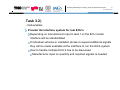
Developing a Methodology for Certifying Heavy Duty Hybrids based on HILS 10th 1 of October 2012 Working Paper No. HDH-11-04e (11th HDH meeting, 10 to 12 October 2012) GRPE-HDH Research Project 11th meeting of the GRPE informal group on heavy duty hybrids (HDH) Report of the Institutes on validation test program 1 Jonas Fredriksson Gérard Silberholz Christoph Six Developing a Methodology for Certifying Heavy Duty Hybrids based on HILS 10th of October 2012 Content Working tasks in current validation phase 1 (until mid-year 2013) Deliverables Current results Timetables and milestones Required manufacturer input Outlook on validation phase 2 2 Developing a Methodology for Certifying Heavy Duty Hybrids based on HILS 10th of October 2012 Validation phase 1 overview Task 1) Adaptation of the Japanese HILS Simulator for serial hybrid 7 sub-tasks where we are currently working on Task 2) Adaptation of the HILS Simulator for parallel hybrid 4 sub-tasks officially starting this month Due to intersections with task 1 already began earlier Task 3) Report on test procedure and adaptations 3 sub-tasks ending on schedule in June 2013 3 Developing a Methodology for Certifying Heavy Duty Hybrids based on HILS 10th 4 of October 2012 Task 1.1) - Deliverables Set up a serial HDH in the simulator with the ECU as software in the loop as basis for further programming and software development Basic serial hybrid model was provided by JARI ECU control strategy with different ICE operation points was added Driver model running the model with a vehicle speed cycle as input Developing a Methodology for Certifying Heavy Duty Hybrids based on HILS 10th of October 2012 Task 1.1) Set up a serial HDH in the simulator with the ECU as software in the loop Basic serial hybrid model was provided by JARI ECU functions were added Hardware ECU interface Software ECU Driver model ECU Switch Hardware/Software 5 Serial hybrid vehicle model Developing a Methodology for Certifying Heavy Duty Hybrids based on HILS 10th of October 2012 Task 1.1) Set up a serial HDH in the simulator with the ECU as software in the loop Driver model running the model with a vehicle speed cycle as input Vehicle cycle input is needed at the driver model Tolerances have to be specified -1sec -2 km/h +2 km/h Tolerance cycles are calculated automatically in MATLAB +1sec 6 Developing a Methodology for Certifying Heavy Duty Hybrids based on HILS 10th of October 2012 Task 1.1) Set up a serial HDH in the simulator with the ECU as software in the loop Driver model running the model with a vehicle speed cycle as input Vehicle cycle input is needed at the driver model Tolerances have to be specified Tolerance cycles are calculated automatically in MATLAB 7 Developing a Methodology for Certifying Heavy Duty Hybrids based on HILS 10th of October 2012 Task 1.1) Set up a serial HDH in the simulator with the ECU as software in the loop Driver model running the model with a vehicle speed cycle as input PID Controller Cycle reference tables Watchdog system 8 Developing a Methodology for Certifying Heavy Duty Hybrids based on HILS 10th of October 2012 Task 1.1) Set up a serial HDH in the simulator with the ECU as software in the loop Simulation results Input: vehicle cycle + permitted tolerances + ICE operation strategy Pedal position [-] Speed [km/h] Output: ICE torque- and speed cycle, tolerance cycle violation time [s] 9 Developing a Methodology for Certifying Heavy Duty Hybrids based on HILS 10th of October 2012 Task 1.1) Set up a serial HDH in the simulator with the ECU as software in the loop Simulation results Input: vehicle cycle + permitted tolerances + ICE operation strategy Eng. Torque [Nm] Eng. speed [rpm] Output: ICE torque- and speed cycle, tolerance cycle violation time [s] 10 Developing a Methodology for Certifying Heavy Duty Hybrids based on HILS 10th 11 of October 2012 General preface concerning driving cycles from the previous project phase (linked to current Task 1.2) The final worldwide HILS method should be – as far as reasonable in agreement with the test procedure for conventional engines The review of vehicle related data resulted in power demand cycles at the power pack shaft which are similar to the test cycle for conventional engines (WHTC) This makes the type approval of a hybrid power pack generally more comparable to conventional combustion engines To allow for charging of a hybrid vehicle’s RESS (rechargeable energy storage system) during phases of deceleration, a corresponding negative power course for mechanical braking was added in the existing motoring phases of the WHTC Developing a Methodology for Certifying Heavy Duty Hybrids based on HILS 10th of October 2012 General preface concerning driving cycles from the previous project phase (linked to current Task 1.2) There are three different options for the realisation of the developed World Heavy Duty Hybrid Cycle (WHDHC) B-1) power cycle at the wheel hubs (with WHVC as speed signal) B-2) power cycle at the power pack shaft (with original engine speed signal acc. to WHTC method / WHVC as speed signal) B-3) vehicle speed cycle WHVC 12 Developing a Methodology for Certifying Heavy Duty Hybrids based on HILS 10th 13 of October 2012 Task 1.2) - Deliverables Elaborate a driver model which allows to run the simulator with test cycles consisting on power and rpm at the wheel hub and at the power pack shaft 2 different driver models for power cycle input 2 PID Controllers per driver model needed Cycle reference tables Watchdog system Developing a Methodology for Certifying Heavy Duty Hybrids based on HILS 10th 14 of October 2012 Task 1.2) Elaborate a driver model for power cycles at the hub and at the power pack shaft Example: power pack shaft driver Torque controller controlling driving torque Speed controller controlling load torque Load torque f(vehicle speed) Torque controller Driving torque Desired shaft speed [rpm] (at constant inertia) Speed controller Developing a Methodology for Certifying Heavy Duty Hybrids based on HILS 10th 15 of October 2012 Task 1.1) + 1.2) - Summary Driver models are able to run serial hybrid powertrains Monitoring system detects faulty or undesired system reactions Function check with different input cycles and vehicles Differences between the 3 driving cycle inputs (vehicle speed, power at hub/shaft) are currently under investigation PID control parameter variation for different vehicle configuration Seems to be a moderate effort for accurate results within tolerances Too aggressive control parameters may lead to erratic engine operation To run parallel hybrid powertrains the driver models have to be adapted in the upcoming task 2 (starting this month) Functions for shifting gears and actuating the clutch have to be added Developing a Methodology for Certifying Heavy Duty Hybrids based on HILS 10th of October 2012 Task 1.3) - Deliverables Extend the Simulator with a library for non-electric components (as defined in part one of the project) The result is a set of simulation models of non-electric powertrain components, which are suitable to use in a HILS setup. Non-electric hybrid powertrain topologies (concepts) fits well into the same categories as for electric hybrid powertrains Interesting non-electric powertrain concepts: CVT and flywheel Motor/generator and flywheel Hydraulic or (pneumatic) pump/motor and accumulator 16 Developing a Methodology for Certifying Heavy Duty Hybrids based on HILS 10th Task 1.3) Simulation models for non-electric powertrain components Mathematical models are developed for: Flywheel Accumulator Pump/Motor CVT 17 of October 2012 Developing a Methodology for Certifying Heavy Duty Hybrids based on HILS 10th of October 2012 Task 1.3) - Summary Mathematical models for non-electric components are available in MATLAB/Simulink Simple models suitable for HILS Input and output signals are defined Models not implemented in the Simulator yet (Japanese open-source model) 18 Developing a Methodology for Certifying Heavy Duty Hybrids based on HILS 10th of October 2012 Task 1.4) - Deliverables Meetings with OEM’s and stakeholders to discuss relevant components to be included in a first version of the GTR-HILS model as basis for tasks 1.5 and 1.6 Input of the Institutes List with already available components List with signals at the ECU-Hardware interface of the model Dialogue and manufacturer input is needed Provided lists should be a basis for discussion Also component test methods have to be reviewed with manufacturers Meeting at the beginning of Nov. in Stuttgart is aimed If we get no input we can only rely on the information from the Japanese model (will not be sufficient) 19 Developing a Methodology for Certifying Heavy Duty Hybrids based on HILS 10th of October 2012 Task 1.5) - Deliverables Extend the Simulator with a library for power pack components not yet included in the Japanese HILS model Components are modelled according to the manufacturers input in task 1.4 Currently a planetary gearbox is offered and already under development Will most likely be used for parallel hybrids in task 2 Planetary gearbox models without inertias and losses already implemented in the library Models considering gear inertias and losses under development Manufacturer input is needed for component testing methods and available model input parameters (e.g. how efficiencies are specified) 20 Developing a Methodology for Certifying Heavy Duty Hybrids based on HILS 10th of October 2012 Task 1.5) - Extend the Simulator with a library for power pack components Planetary gearbox for power split 3 basic models are provided in the library Gearbox output at: Sun gear Ring gear Planet gear carrier Models require: Planet carrier Sun gear Gear tooth numbers Component inertias Gear efficiencies (S-P,P-R) Validation through other software (GT-Suite, Dymola) Ring gear Source: www.csa.com 21 Planet gears Developing a Methodology for Certifying Heavy Duty Hybrids based on HILS 10th 22 of October 2012 Task 1.6) - Deliverables Extend the GTR-HILS Simulator with thermal models for exhaust gas aftertreatment components, coolant, lube oil, battery and electric motor In previous project phase it was decided that HDH will have to undergo a cold start test similar to the conventional ICEs HDH ECUs will need plausible information on the temperature levels of all relevant components to select the correct operation strategies Simple thermal models with generic input parameters are being developed / adapted and integrated into the HILS simulator Developing a Methodology for Certifying Heavy Duty Hybrids based on HILS 10th of October 2012 Task 1.6) Extend the GTR-HILS Simulator with thermal models Thermal models for exhaust gas aftertreatment components implemented in Simulink validation with existing measurement data finished ready to be linked to the main Simulink model 23 Developing a Methodology for Certifying Heavy Duty Hybrids based on HILS 10th 24 of October 2012 Task 1.6) Extend the GTR-HILS Simulator with thermal models Thermal models for exhaust gas aftertreatment components 2 separate aftertreatment systems (i.e. DOC/POC and SCR) modeled 0-dimensional heat capacities Heat transfer between exhaust gas and heat capacities: convection (turb. / lam.) Catalyst: heat input through chemical reactions (conversion rate maps) Cooldown of stopped engine (empiric cool down curve) Developing a Methodology for Certifying Heavy Duty Hybrids based on HILS 10th 25 of October 2012 Task 1.6) Extend the GTR-HILS Simulator with thermal models Thermal models for exhaust gas aftertreatment components Heat transfer between heat capacities and environment: convection, radiation Heat conduction between masses neglected (effect much smaller than 0-d model accuracy) Thermal behavior of thermocouples included (essential for comparison of model results with measurement data) Developing a Methodology for Certifying Heavy Duty Hybrids based on HILS 10th 26 of October 2012 Task 1.6) Extend the GTR-HILS Simulator with thermal models Thermal models for exhaust gas aftertreatment components Input signals: engine speed, power, vehicle speed, engine status Maps: exhaust gas temp after turbocharger, exhaust gas massflow, lambda, emissions, conversion rates in catalyst Input parameters: masses, start temperatures, heat capacities, heat transfer coefficients, lengths & diameters of pipe sections Developing a Methodology for Certifying Heavy Duty Hybrids based on HILS 10th of October 2012 Task 1.6) Extend the GTR-HILS Simulator with thermal models Thermal models for exhaust gas aftertreatment components maps for temperature exh. out, lambda, massflow maps for emissions Calculations in MATLAB code maps for conversion rates of catalyst 27 Developing a Methodology for Certifying Heavy Duty Hybrids based on HILS 10th 28 of October 2012 Task 1.6) Extend the GTR-HILS Simulator with thermal models Thermal model for coolant and lube oil implemented in Simulink measurements on engine testbed for parameterization of model currently running needs to be adapted, parameterized and validated with measurement data Developing a Methodology for Certifying Heavy Duty Hybrids based on HILS 10th 29 of October 2012 Task 1.6) Extend the GTR-HILS Simulator with thermal models Thermal model for coolant and lube oil (exemplarily for coolant) Cooling circuit divided into 2 cells 0-dimensional heat capacities for ICE & cooler 4 equations: (I) cICE mICE dTICE Qin W 1 AW 1 TICE TW 1 dt (II) cW mW 1 dTW 1 W 1 AW 1 TICE TW 1 cW m TW 1 TW 2 dt (III) cW mW 2 dTW 2 cW m TW 1 TW 2 W 2 AW 2 TC TW 2 dt (IV) cC mC TW1 dTC W 2 AW 2 TC TW 2 Air AAir TAmb TC dt Open: simulate engine test conditions with constant Tcooler Or vehicle conditions with variable Air TW2 Developing a Methodology for Certifying Heavy Duty Hybrids based on HILS 10th 30 of October 2012 Task 1.6) Extend the GTR-HILS Simulator with thermal models Thermal models for battery and electric motor under preparation in cooperation with Institute of Electrical Measurement and Measurement Signal Processing at TUG OEM input and validation data needed Developing a Methodology for Certifying Heavy Duty Hybrids based on HILS 10th 31 of October 2012 Task 1.6) Extend the GTR-HILS Simulator with thermal models Thermal model for electric storage device From Kokujikan No. 281: Actual state of charge - coulomb counting: Calculation of the electrical power: Required Extensions to calculate battery and fluid temperatures: Adding a time dependence (time constant) for the current/voltage behavior Adding a thermal model of the battery pack Calculation of the power loss and in combination with the thermal battery pack model calculation of the temperatures Developing a Methodology for Certifying Heavy Duty Hybrids based on HILS 10th 32 of October 2012 Task 1.6) Extend the GTR-HILS Simulator with thermal models Thermal model for electric storage device Time dependence of current / voltage behavior Measured voltage behavior due to a rectangular current pulse (commercial 70Ah Kokam LiPoly cell) Time dependence is required for a better estimation of the power loss Parameter estimation: Almost the same measurements as described in Kokujikan No. 281 but different data analysis needed. - No time dependent model as shown in Kokujikan No. 281 - Time dependent model Developing a Methodology for Certifying Heavy Duty Hybrids based on HILS 10th 33 of October 2012 Task 1.6) Extend the GTR-HILS Simulator with thermal models Thermal model for electric motor From Kokujikan No. 281: Model calculates torque, electric power and current in dependence of revolution speed, voltage and torque demand Required Extensions to calculate motor, controller and fluid temperatures: Separation of power losses for EM and controller (leading also to individual power consumption maps for the motor and controller) Adding thermal models of motor and controller Combining the calculated power losses and the thermal models calculation of the corresponding temperatures Developing a Methodology for Certifying Heavy Duty Hybrids based on HILS 10th of October 2012 Task 1.6) Extend the GTR-HILS Simulator with thermal models Thermal model for one component (battery, motor, controller) Thermal mass is considered as a point mass Heat transfer is modeled by a constant heat transfer coefficient Pressure drop for fluid flow is stored in a lookup table Parameter estimation: Same measurements as described in Kokujikan No. 281 but additional measurement between controller and motor is needed. 34 Developing a Methodology for Certifying Heavy Duty Hybrids based on HILS 10th of October 2012 Task 1.7) - Deliverables Simulation runs and validation of basic functions Simple control strategy for model validation (including vehicle-, driver-, thermal- and non-electric models) With regard to validation phase 2, models of later on tested vehicles should be used for validation here Largely realistic control strategy would be favourable Different input data will be used Generic values Measurement data from institutes Measurement data from manufacturers if available 35 Developing a Methodology for Certifying Heavy Duty Hybrids based on HILS 10th 36 of October 2012 Validation phase 1 overview Task 1) Adaptation of the Japanese HILS Simulator for serial hybrid Timetable and milestones Task 1.1) and 1.2) serial hybrid model with different driver models are completed Task 1.3) modelling non-electric components is finalized, overall model-implementation deferred with regard to validation phase 2 Task 1.5) and 1.6) modelling of components and thermal models is planned to end in November to have enough time for overall model validation which should start in December Task 1 report to ACEA at the end of February Jun 1 SILS for serial hybrid 1,1 Set up a serial HDH as SILS 1,2 Adapt driver model 1,3 Library for non electric com Meetings with OEM’s and 1,4 stakeholders Library for new power pack 1,5 components 1,6 Thermal models 1,7 Simulation runs and validation Jul Aug Sept Oct Nov Dec Jan Feb Mar Apr May Developing a Methodology for Certifying Heavy Duty Hybrids based on HILS 10th of October 2012 Validation phase 1 overview Task 1) Adaptation of the Japanese HILS Simulator for serial hybrid 7 sub-tasks where we are currently working on Task 2) Adaptation of the HILS Simulator for parallel hybrid 4 sub-tasks officially starting this month Due to intersections with task 1 already began earlier Task 3) Report on test procedure and adaptations 3 sub-tasks ending on schedule in June 2013 37 Developing a Methodology for Certifying Heavy Duty Hybrids based on HILS 10th Task 2.1) - Deliverables Meetings with OEM’s and stakeholders See Task 1.4 38 of October 2012 Developing a Methodology for Certifying Heavy Duty Hybrids based on HILS 10th of October 2012 Task 2.2) - Discussion point Set up a data bus system in the model to allow various combinations of engines, gear boxes and storage systems Difficult in the current model to setup a data bus system Components are represented in different ways in the two vehicle models Components are lumped in different ways There might be a need to restructure the models 39 Developing a Methodology for Certifying Heavy Duty Hybrids based on HILS 10th e l E c i r t c d i r b Hy i r e s ( ) s e e l E c i r ct id r b y H 40 of October 2012 l l a r a p ( ) l e Developing a Methodology for Certifying Heavy Duty Hybrids based on HILS 10th of October 2012 Task 2.2) - Discussion point Set up a data bus system in the model to allow various combinations of engines, gear boxes and storage systems Bring up the question (“who is the owner of the model in the end”) Who is responsible for structure, who for components; Are these different persons/authorities? -> model will never be “plug&play” Manufacturers should be able to bring in their own submodels, we can only provide a minimum of signals that are needed 41 Developing a Methodology for Certifying Heavy Duty Hybrids based on HILS 10th 42 of October 2012 Task 2.3) - Discussion point Adapt the Software to simulate a parallel HDH Would be good if we know which drivetrain topologies we will have in validation phase 2 (to prepare parallel and serial HDH models) Task 2 already starting In need of control strategy? Depend on topology! Idea of control strategy! Is this acceptable for doing simulations? Developing a Methodology for Certifying Heavy Duty Hybrids based on HILS 10th 43 of October 2012 Task 2.3) - Deliverables Adapt the Software to simulate a parallel HDH In need of control strategy? Depend on topology! Idea of control strategy! Is this acceptable for doing simulations? The control strategy is to use the electric machine below a certain speed and the combustion engine above that. If energy level stored in the accumulator is lower than a certain value, the electric machine is used as generator and is then driven either by the engine or purely by the kinetic energy of the vehicle. The electric machine is used for braking the vehicle when possible, if the brake torque is not enough then the mechanical brakes are used as well. The electric machine is also used for power assist when the desired torque, interpreted from the accelerator pedal position, is larger than the combustion engine can deliver. Developing a Methodology for Certifying Heavy Duty Hybrids based on HILS 10th 44 of October 2012 Task 2.4) - Deliverables Simulation runs and validation of basic functions, including the functions from task 1 See Task 1.7) Generic data or measurement data of institutes or manufacturers will be used Depending on vehicles in validation phase 2 Provided simulation models have to be specified Models for all possible combinations of library components will not be provided Developing a Methodology for Certifying Heavy Duty Hybrids based on HILS 10th 45 of October 2012 Validation phase 1 overview Task 2) Adaptation of the HILS Simulator for parallel hybrid Timetable and milestones Task 2.2) the model structure and the further proceeding has to be discussed at earliest Task 2.3) control strategy proposal has to be discussed Task 2.4) available vehicles in validation phase have to be specified Jun 2 2,1 2,2 2,3 Adaptation of SILS for parallel hybrid Meetings with OEM’s and stakeholders Set up a data bus system in the model Adapt the Software to parallel HDH 2,4 Simulation runs and validation Jul Aug Sept Oct Nov Dec Jan Feb Mar Apr May Developing a Methodology for Certifying Heavy Duty Hybrids based on HILS 10th of October 2012 Validation phase 1 overview Task 1) Adaptation of the Japanese HILS Simulator for serial hybrid 7 sub-tasks where we are currently working on Task 2) Adaptation of the HILS Simulator for parallel hybrid 4 sub-tasks officially starting this month Due to intersections with task 1 already began earlier Task 3) Report on test procedure and adaptations 3 sub-tasks ending on schedule in June 2013 46 Developing a Methodology for Certifying Heavy Duty Hybrids based on HILS 10th 47 of October 2012 Task 3.1) - Deliverables Report on test procedure and user manual for software Component testing procedure Application of the HILS simulator Validation procedure of the HILS setup User manual for the software Reports can only be on schedule if we agree to keep working with the current HILS model structure Developing a Methodology for Certifying Heavy Duty Hybrids based on HILS 10th 48 of October 2012 Task 3.2) - Deliverables Provide the interface system for real ECU’s Depending on manufacturer input in task 1.4) the ECU model interface will be standardized If individual vehicles in validation phase 2 request additional signals they will be made available at the interface to run the HILS system How to handle multiple ECU’s has to be discussed Manufacturer input on quantity and required signals is needed Developing a Methodology for Certifying Heavy Duty Hybrids based on HILS 10th 49 of October 2012 Task 3.3) - Deliverables & comments Adaptations and improvements on the methods for component testing, test cycle definition and simulation method according to demands of industry and Commission For eventual adaptation and improvement of methods suggested by the HDH group, two weeks of work is reserved Maybe transient model behaviour will get a topic Currently transfer functions and time constants are used (e.g. for ICE torque buildup) Not clear how they are specified in the component test methods Effort tuning the time constants can not be estimated today, at earliest possible in validation phase 2 Developing a Methodology for Certifying Heavy Duty Hybrids based on HILS 10th 50 of October 2012 Validation phase 1 overview Task 3) Report on test procedure and adaptations Timetable and milestones Reporting to ACEA will start in January (only Task 1) Total validation phase 1 report is planned to start on schedule Reports can only be on schedule if we agree to keep working with the current HILS model structure Changing the model structure will postpone the targeted end of validation phase 1 but may be advantageous for modelling future hybrid vehicles Jun 3 3,1 3,2 3,3 Reporting on test procedure and writing a user manual for software Report on test procedure, user manual Provide the interface system for real ECU’s Adaptations and improvements of methods Jul Aug Sept Oct Nov Dec Jan Feb Mar Apr May Developing a Methodology for Certifying Heavy Duty Hybrids based on HILS 10th 51 of October 2012 Outlook on validation phase 2 (from spring 2013) Validation phase 2 influences current work Certain points have to be clarified at earliest (see previous slides) Still an open question is who will work on validation phase 2 and which vehicles will be tested We will not provide vehicle models which are not used in validation phase 2 We propose to leave the non-electric components outside the model in the library and focus on modelling vehicle structures tested in validation phase 2 Developing a Methodology for Certifying Heavy Duty Hybrids based on HILS 10th 52 of October 2012 THANK YOU FOR YOUR ATTENTION! Jonas Fredriksson Gérard Silberholz Christoph Six [email protected] [email protected] [email protected]