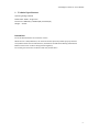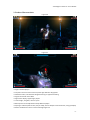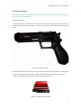
1
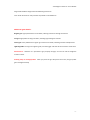
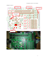
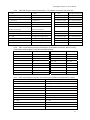
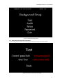
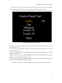
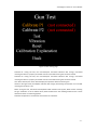
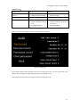
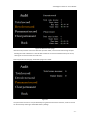
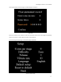
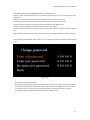
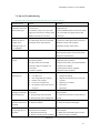
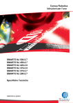
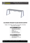
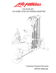
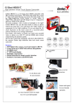
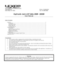
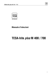
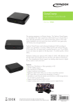
“Flashlight of the Evil” User Manual
“Flashlight of the Evil” Product User Manual Product Name: Flashlight of the Evil Developed by Guangzhou Sealy Electronic Technology Co. Ltd About this user manual This user manual is intended to get users familiar with our “Flashlight of the Evil” product. It contains details about the proper use and precautions. It also provides solutions to problems you may encounter while using our game. Users can find more information about this product through other means by contacting our Company. Your valuable opinions and advice are greatly appreciated. Description about the identification used in this manual and on the product The logos are included both on this manual and on the product to facilitate the user’s operation of our product. LOGO of the “Flashlight of the Evil” -1-
“Flashlight of the Evil” User Manual
Table of Contents 1. Technical Specifications ------------------------------------------------------------- - 3 - 2. Product Characteristics---------------------------------------------------------------- - 4 - 3. Game Introduction---------------------------------------------------------------------- - 5 - 4. Hardware User Guide (Game Computer Set Portion)--------------------------- - 8 - 5. Unit Installation ------------------------------------------------------------------------- 14 - 6. User Settings Guide --------------------------------------------------------------------- 18 - 7. FAQ and Troubleshooting ------------------------------------------------------------- 26 - 8. Instructions for Game Auto Update ------------------------------------------------- 27 - -2-
“Flashlight of the Evil” User Manual
1. Technical Specifications
Operating Voltage: 220VAC Rated Power: 500W(Single Unit) Dimensions: 2980mm(L) X 2040mm(W) X 2703mm(H) Weight: 550 KG Precautions Do not hit with hard items or scratch the screen! While the unit is still powered on, do not touch the fan system to prevent injury by the fans! The product needs care and maintenance; malfunctions should be handled by professionals! Make sure the screen surface is being cleaned regularly! Do use the guns to hit other surfaces and do not pull the wires! -3-
“Flashlight of the Evil” User Manual
2. Product Characteristics
Figure 2.0 Figure 2.1 * Single or Double players * Scary but humorous at the same time, with high definition 3D graphics * Adventure mode, oversized boss designed to bring an oppressive feeling * Original sound and music effect * Huge screen display, supporting 2 players * 4 main stages, 2 big boss, choice is yours * Difficulty level can be adjusted to satisfy different players * Simple gun and foot pedal control, easy to adapt, various weapons and accessories, many gameplays * Perfect combination of horror and monster fighting thrills -4-
“Flashlight of the Evil” User Manual
3. Game Introduction
This section describes the gameplay and information related to the game. Please read carefully if this is the first using this product. Weapon description: The player’s weapon includes a gun and a foot pedal. The gun has a trigger as the shooting control, when holding the gun maintain about 1.3 meters away from the screen. Sample picture of the gun below. Figure 3.1 Sample of the gun Besides when hinted by the game, for change of weapon or QTE and other operations, you will need to achieve by pressing the foot pedal. A sample of the foot pedal is illustrated in the picture 3.2 below. The foot pedal is located on each side left and right of the seat. Figure 3.2 Sample of the foot pedal -5-
“Flashlight of the Evil” User Manual
The game display setting between 3D and regular non‐3D can be switched with the 2D/3D key in the middle of the machine. The switch looks like the picture 3.3 below. Figure 3.3 2D/3D Switch Gameplay description: The player inserts the coin into the coin acceptor, the game will start when the player uses the gun. The player can select between stage clearing mode and free mode. When the stage clearing mode is selected, only two stages are available while the other two would automatically become available once the first two stages are cleared. When the free mode is selected, the player would continuously attack enemies without time limit. After the game starts, the player lifts up the gun and points at the screen where a crosshair would appear. Pulling the trigger would attack the enemy, if the player holds the trigger it would activate the lightning blade feature which can be used to slash the enemies. Hitting the foot pedal will change the property of the gun. Hitting the pedal and pulling the trigger at the same time can skip the CG narrative scene. Players can earn extra points by hitting the circled weak points and lit up accessories. When the game is over, the score is calculated and displayed on the score board. Game modes: Stage mode and Free mode -6-
“Flashlight of the Evil” User Manual
Stage mode: different stages will have different game stories Free mode: eliminate as many enemies as possible in unlimited time. Additional game details: Regular gun: high speed and short cool down, inflicting continuous damage to enemies. Fire gun: high power but long cool down, inflicting high damage to enemies. Freeze gun: more powerful that regular gun and shot cool down, attacking enemies multiple times. Lightning blade: turning into a lightning rod, hold the trigger and wave at the enemies to slash them. Pedal feature:whenever it is pressed the gun property changes, can also be used to dodge the enemies’ attack. Pointing away to recharge/reload:when you point the gun away from the screen, the gun power gets recharged instantly. -7-
“Flashlight of the Evil” User Manual
4. Hardware User Guide (Game Computer Set Portion)
4.1 Flashlight of the Evil Appearance Figure 4.1 Flashlight of the Evil Frame -8-
“Flashlight of the Evil” User Manual
4.2 Expansion Board Function port
Function port
Function port
Port to main
computer
Power port
Photo of the actual expansion board -9-
“Flashlight of the Evil” User Manual
4.2.a CN1:LED Output Control Connection(Pin header connector 50P‐2.54‐Pin) 27、+12V 28、Right pedal light R
4、+12V 29、Right pedal light G 30、Right pedal light B
5、Internal mono light rod 6、+12V 31、+12V 32、Reserved output 7、Effect fan 1 8、Effect fan 2 33、Reserved output 34、Reserved output 9、Effect fan 3 10、Effect fan 4 35、+12V 36、Reserved output 11、Wind blower, connect to IO board 12、 37、Reserved output 38、Reserved output 13、Vibration device 1, connect to 14、Vibration device 2, connect to 39、+12V 40、Reserved output 1、+12V 2、+12V 3、+12V vibration driver board vibration driver board 15、+12V 16、Left side red light strip R 41、Reserved output 42、Reserved output 17、Left side red light strip G 18、Left side red light strip B 43、+12V 44、Reserved output 19、+12V 20、Right side red light strip R 45、Reserved output 46、Reserved output 21、Right side red light strip G 22、Right side red light strip B 47、+12V 48、Reserved output 23、+12V 24、Left pedal lightR 49、Reserved output 50、Reserved output 25、Left pedal light G 26、Left pedal light B 4.2.b CN2: Input Output Function Connection (Pin header connector 40P‐2.54‐Pin), 3‐set motor control signal (1‐12) plus shielded ground 1、 2、 21、 22、 3、 4 23、 24、 5 6 25、+12V 26、、+12V 7 8 27、+5V 28、+5V 9 10 29、+5V 30、+5V 11 12 31、+5V 32、+5V 13 14 33、GND 34、GND 15 16 35、GND 36、GND 17、 18 37、GND 38、GND 19、Internal reserved key 1 20、Internal reserved key 2
39、GND 40、GND 4.2.c CN3: Input Output Function Connection (pin header connector26P‐2.54‐pin) 1、Foot pedal 1 2、Foot pedal 2 3、2D switch 4、Background settings key 1 5、Background settings key 2 6、Background settings key 3 7、Coin signal input 1 8、Coin signal input 1 9、 10、 11、2D switch light 12、Redeem output 1 13、GND 14、Redeem output 2 15、+12V 16、Redeem input 1 17、+12V 18、Redeem input 2 19、+12V 20、GND 21、+12V 22、GND 23、+12V 24、GND 25、+12V 26、GND - 10 -
“Flashlight of the Evil” User Manual
4.2.d CN4: Power Connection(A3963WV2‐4P) 1、+12V 2、+12V 3、GND 4、GND 4.2.e CN5:Reserved for future use (no connection) 4.3 Vibration device driver board Photo of actual connection of driver board - 11 -
“Flashlight of the Evil” User Manual
4.3.a P1: Main control board vibration signal+ Main output power control (2,3 pins not used) 1.Vibration 2. 3. 4.+12V 5.GND input+ 4.3.b P2:Driver board Input power (single 12V power source) + vibration device driver output 1.GND 2.+12V 3.motor negative output 4. Motor positive output 4.4 Blower driver board Photo of actual blower driver board - 12 -
“Flashlight of the Evil” User Manual
4.4.a CN1:Motol connection(A3963WV2‐4P) 1、Power input+ 2、Power input ‐ 3、Motor‐ 4、Motor+ 4.4.b CN2: Input control connection(A2501WV2‐2P) 1、Blower input control signal 2、+12V 4.5 H61Computer host connections: Ethernet
Power
Display
Not
and USB
connection
port
used
ports
RS232 serial port,
the one above
connects to control
board
Sound input and output
ports
- 13 -
“Flashlight of the Evil” User Manual
5. Unit Installation
Game machine structure and parts illustrated in picture below: Figure 5.1 Machine broken down structure picture The assemble process is composed of 7 steps, please follow the instructions below. 1)
First step When mounting this
portion, make sure the
holes are aligned, then
screw to tighten.
Figure 5.2 2)
Step 2 - 14 -
“Flashlight of the Evil” User Manual
These two parts are identical
Make sure holes are
aligned before screwing
Figure 5.3 3) Step 3 Make sure the chains are tightened
up so they appear straight.
图 5.4 4) Step 4 - 15 -
“Flashlight of the Evil” User Manual
Connect the two parts then screw.
Align the holes
Figure 5.5 5) Step 5 Connect the top and side panels,
aligning the holes and screw
before installing the curtain.
Connect these two parts,
aligning them and screw to
tighten them.
Figure 5.6 6) Step 6 After the two major parts
are connected, install the
middle board and foot
board.
- 16 -
“Flashlight of the Evil” User Manual
Align the holes
before screwing.
Figure 5.7 7) Step 7 Align
After
the
frame
is
assembled, align the back
to mount the decorations.
Figure 5.3 - 17 -
“Flashlight of the Evil” User Manual
6. User Settings Guide
This section talks about how to set the Flashlight of the Evil game parameters. Please read the following section carefully if you are using the product for the first time. It describes each settings option in detail, and helps the user familiarize with the unit and understand the effects of each one of them. 6.1 Accessing the back end: Only the management personnel can access the back end compartment, which is through the door that houses the coin acceptor (figure 1.1 below), it is locked and can be opened with the key provided. Key slot
Figure 1.1 After you opened the door, press the right‐most red button to access the back‐end settings menu. The two left‐most are not used, each key’s function is described on the picture 1.2 below. Reserved
Reserved 2
Confirm Key
Select Key
Key to access
back-end settings
6.2. Getting into the Settings Menu When the game is loaded, press the back‐end settings key to access the Settings menu. The back‐end settings interface contains 5 options: Testing, Audit, Settings, Password and Exit, as illustrated by the following picture. - 18 -
“Flashlight of the Evil” User Manual
Figure 6.1 Backend Settings Menu 6.3 Background Setup Interface Description 6.3.A. The Test option includes the test of the gun and the control panel, illustration below: Figure6.2 Peripheral input output test page - 19 -
“Flashlight of the Evil” User Manual
When the gun and control panel are properly connected the display will show “connected”, otherwise showing “not linked”. The test cannot be done if hardware is not connected. The test of the control board includes testing the lights, fans, vibration seat and keys (figure 6.3): Treadle 1P
Treadle 2P
Figure 6.3 Control Board Testing page Lights: during the test, the ON/OFF indication will change, ON meaning the device is on and OFF meaning the device is off. Fan: during the test, the ON/OFF indication will change, ON meaning the device is on and OFF meaning the device is off. Vibration: during the test, the ON/OFF indication will change, ON meaning the device is on and OFF meaning the device is off. Treadle 1P: during the test, the RELEASED/PRESSED indication will change, RELEASED meaning the device is not pushed, PRESSED meaning it is pushed. Treadle 2P: during the test, the RELEASED/PRESSED indication will change, RELEASED meaning the device is not pushed, PRESSED meaning it is pushed. The test of the gun includes testing and calibration of the gun, interface as below (figure 6.4): - 20 -
“Flashlight of the Evil” User Manual
Figure 6.4 Gun Testing page Calibrate P1: during the test, the Connected/not connected indication will change, Connected meaning the device is properly connected and not connected meaning the connection failed. Calibrate P2: during the test, the Connected/not connected indication will change, Connected meaning the device is properly connected and not connected meaning the connection failed. Test: when selected, the screen would display the operation details of the two guns. Vibration: during the test, the ON/OFF indication will change, ON meaning the vibration is on and OFF meaning the vibration is off. Reset: during the test, the Reset Success/Reset Failed indication will appear, Reset Success meaning the gun calibration is set to default values, Reset Failed means the resetting failed and the current calibration values are still being applied. Calibration Explanation: will show the instructions for calibration. - 21 -
“Flashlight of the Evil” User Manual
Common errors: Common errors Causes Solutions No reaction when key is 1.
Key is damaged 1.
Replace key pressed 2.
Cable not well connected 2.
Reconnect cable Guns for P1,P2 are inverted 1.
Wrong wiring 1.
Reconnect cables Crosshair is not accurate 1.
Hardware not calibrated 1.
Recalibrate 2.
Sensor mounting or wiring 2.
Inspect mounting and wiring of error the sensor 3.
Damaged hardware 3.
Replace hardware 6.3.B Access the Audit page to check the operating revenue details: Figure 6.5 Audit page All the game records saved, including: total coins income, game times, run time, game time, coins addition times, average score, game cleared times, game cleared record. Accessing the Devolve (shift) record page, illustration below (figure 6.6): - 22 -
“Flashlight of the Evil” User Manual
Figure 6.6 Devolve record page Records of the previous and current business operation shifts, convenient for shift change analysis. Holding the confirm button for 3 seconds will transfer the current record data to the prior record, clearing the current record at the same time. Accessing the Permanent page, illustrated by figure 6.7 below: Figure 6.7 The permanent records can only be deleted by using the Clear Permanent function, all other records can be cleared by restoring to the default factory settings. - 23 -
“Flashlight of the Evil” User Manual
Accessing the Clear permanent page, illustrated by figure 6.8 below: Figure 6.8 Enter the password, press confirm to clear the permanent records. If the user forgot the password, he/she can contact our client support to obtain a new password. 6.3.C Accessing the Setup page, as illustrated by figure 6.9 below: Figure 6.9 Setup page - 24 -
“Flashlight of the Evil” User Manual
Enter the following factory password 000000 to load the Setup page. Coins per stage: sets the number of coins required to start the game, also for continuing the game. Range 0 to 9. Difficulty: sets the difficulty level of the game, broken down in 3: easy, normal, hard. Sound volume: sets the sound volume, range 0 to 10, the higher the value the louder. Vibrate rate: sets the vibration frequency of the seat, range 0 to 120, default is 50. Language: sets the language of the game, includes Chinese and English. Default setup: jumps to the factory setup page, the distributor number can be set if it was not done yet. Reset to default: clears the total records, devolve records, gun calibration values will be set to default. 6.3.D Accessing the Password option allows user to change the password, illustration below (figure 6.10): Figure 6.10 Game software update instructions: Firstly contact client support to obtain the update patch and store it on the root location of a USB flash drive. While the unit is powered off, insert the flash drive into the USB port, then boot on the unit. Wait for the unit to boot up and reboot automatically, meaning the software has been successfully updated. Unplug the USB flash drive when update is done. - 25 -
“Flashlight of the Evil” User Manual
7. FAQ and Troubleshooting
This section describes the commonly observed errors and their solutions: Common errors Causes Solutions No response from 1. Power not adequate 1. Check power is adequate for unit use computer and screen 2. Fuse burnt 2. Replace fuse after powering on 3. If display“无输入信号”(no input 3. Verify 220VAC power is functional, switch signal) for more than 1 minute, check is on, and make sure signal cable is well HDMI connection for anomaly connected Power on, sound 1. No power to the monitor 1. Check power connection to the monitor functional, but no 2. Video signal cable not connected 2. Check the video signal cable connection image and no 3. Monitor driver board broken between monitor and computer 3. Replace monitor driver board message“无输入信
号” displayed No 3D effect 1. Monitor driver error 2. Adjust with remote controller or contact client support to get a new monitor driver program as replacement There is image but no 1. Volume is set to minimum 1. Adjust the volume to optimal level sound 2. Broken speakers 2. Replace broken speakers 3. Audio cable not connected 3. Check audio cable is connected between 4. Power supply to amplifier not computer and amplifier connected 4. Check power cable to amplifier 5. Broken amplifier 5. Replace broken amplifier No response after 1.
Coin did not get accepted 1.
Re‐insert a new coin inserting coin 2.
Free game set 2.
Change the setting 3.
Replace the reference coin in the coin 3.
Not recognized coin inserted 4.
Broken coin acceptor 5.
Loose coin acceptor wire 4.
Replace coin acceptor 6.
No 12V DC current into the coin 5.
Reconnect acceptor 6.
Reconnect acceptor Unable to access 1. Computer and IO board not 1. Check the IO board port is connected to background settings connected host computer with Settings key 2. Wrong wiring to the IO board 2. Check the connection to the IO board is 3. Wrong wiring to the settings key correct Lights, fans or 1. Wrong wiring to IO board 1. Check connection to IO board is correct vibration seat do not 2. Broken hardware 2. Check if hardware is damaged 2/3D switch, 1p pedal 1. No serial connection between IO 1. Check IO board is properly connected to or 2p pedal do not board and host computer host computer respond 2. Wrong IO board wiring 2. Make sure IO board wiring are correct 3. Broken or dysfunctional hardware
3. Check for broken hardware respond (Table 7.1) - 26 -
“Flashlight of the Evil” User Manual
8. Instructions for Game Auto Update
Perform the automatic game software update with a USB flash drive. Steps and key notes: 1. Prior to doing the update, make sure the file on the flash drive is named update.xli, and is stored on the root location; 2. When the game is running, plug the flash drive to the host computer USB port (you will need to unplug one of the current connection); If the game automatically stopped and rebooted the computer, it means the update was successful, at that moment unplug the flash drive, update is done. If the update failed, repeat the steps above. - 27 -