1
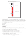
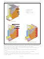
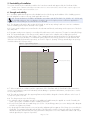
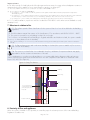
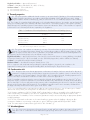
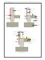
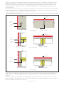
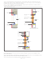
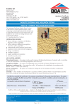
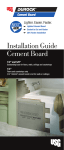
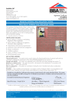
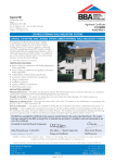
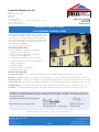
Eurobrick Building Systems Ltd
APPROVAL
INSPECTION
TESTING
CERTIFICATION
Unit 7
Wilverley Trading Estate
Bath Road
Brislington
Bristol BS4 5NL
Tel: +44 (0)117 971 7117 Fax: +44 (0)117 971 7217
TECHNICAL APPROVALS FOR CONSTRUCTION
Agrément Certificate
13/5079
e-mail: [email protected]
website: www.eurobrick.co.uk
Product Sheet 1
EUROBRICK CLADDING SYSTEMS
X-CLAD EXTERNAL CLADDING SYSTEM
This Agrément Certificate Product Sheet (1) relates to the
X-Clad External Cladding System, an insulated clay brick
slip system for use as protective/decorative cladding
with or without a cavity over solid masonry, timber- and
steel-frame external walls in new and existing domestic
and non-domestic buildings.
(1) Hereinafter referred to as ‘Certificate’.
CERTIFICATION INCLUDES:
• factors relating to compliance with Building
Regulations where applicable
• factors relating to additional non-regulatory
information where applicable
• independently verified technical specification
• assessment criteria and technical investigations
• design considerations
• installation guidance
• regular surveillance of production
• formal three-yearly review.
KEY FACTORS ASSESSED
Strength and stability — the system can adequately resist wind loads and impact damage (see section 6).
Behaviour in relation to fire — the system is classified Class 0 or ‘low risk’ surface spread of flame (see section 7).
Thermal properties — the system contributes to the overall thermal performance of the wall construction (see section 9).
Condensation risk — the system can contribute to limiting the risk of interstitial and surface condensation (see section 10).
Weathertightness — the system resists water penetration and the risk of damage to the inner wall (see section 11).
Durability — with appropriate maintenance, the system will remain effective for at least 25 years (see section 13).
The BBA has awarded this Certificate to the company named above for the system described herein. This system
has been assessed by the BBA as being fit for its intended use provided it is installed, used and maintained as set
out in this Certificate.
On behalf of the British Board of Agrément
Date of First issue: 6 January 2014
Brian Chamberlain
Claire Curtis-Thomas
Head of Approvals — Engineering
Chief Executive
The BBA is a UKAS accredited certification body — Number 113. The schedule of the current scope of accreditation for product certification is
available in pdf format via the UKAS link on the BBA website at www.bbacerts.co.uk
Readers are advised to check the validity and latest issue number of this Agrément Certificate by either referring to the BBA website or contacting the BBA direct.
British Board of Agrément
Bucknalls Lane
Watford
Herts WD25 9BA
©2014
Page 1 of 15
tel: 01923 665300
fax: 01923 665301
e-mail: [email protected]
website: www.bbacerts.co.uk
Regulations
In the opinion of the BBA, the X-Clad External Cladding System, if installed, used and maintained in accordance with
the provisions of this Certificate, will meet or contribute to meeting the relevant requirements of the following Building
Regulations (the presence of a UK map indicates that the subject is related to the Building Regulations in the region or
regions of the UK depicted):
The Building Regulations 2010 (England and Wales) (as amended)
Requirement: A1
Loading
Comment:
The system can sustain and transmit wind loads to the substrate as set out in sections 4.4, 4.5, 4.7 and
6.2 of this Certificate.
Requirement: B4(1)
External fire spread
Comment:
Requirement: C2(b)
Resistance to moisture
The system meets Class 0 requirement. See sections 7.1 to 7.4, 7.6 and 7.7 of this Certificate.
Comment:
The system will resist the passage of rainwater to the supporting structure. See sections 11.1 to 11.5 of
this Certificate.
Requirement: C2(c)
Resistance to moisture
Comment:
The system contributes to minimising the risk of surface and interstitial condensation. See sections 10.1 to
10.2 of this Certificate
Requirement: L1(a)(i)
Conservation of fuel and power
Comment:
Regulation:
Materials and workmanship
The system can contribute to meeting this Requirement. See sections 9.1 to 9.4 of this Certificate.
7
The system is acceptable see section 13 and the Installation part of this Certificate.
Comment:
Requirement: 26
CO2 emission rates for new buildings
Comment:
Walls can contribute to meeting the Target Emission Rate. See sections 9.1 to 9.4 of this Certificate.
The Building (Scotland) Regulations 2004 (as amended)
Regulation:
8(1)(2)
Regulation:
Standard:
9
1.1(b)
2.6
2.7
3.10
3.15
6.1(b)
6.2
7.1(a)(b)
Comment:
Statement of sustainability
The system can contribute to meeting the relevant Requirements of Regulation 9, Standards 1 to 6, and,
therefore, will contribute to a construction meeting a bronze level of sustainability as defined in this Standard.
In addition, the system can contribute to a construction meeting a higher level of sustainability as defined
in this Standard, with reference to clauses 7.1.4(1)(2) [Aspects 1(1)(2) and 2(1)], 7.1.6(1)(2) [Aspects 1(1)(2) and
2(1)] and 7.1.7(1)(2) [Aspect 1(1)(2)]. See section 9.1 to 9.4 of this Certificate.
Comment:
Regulation:
Carbon dioxide emission
Building insulation envelope
The system will enable, or contribute to enabling, a wall to meet these Standards, with reference to clauses
6.1.1(1)(2), 6.1.4(1), 6.1.5(1), 6.2.1(1)(2), 6.2.3(1), 6.2.4(1)(2), 6.2.5(1)(2), 6.2.6(2) and 6.2.7(2). See sections
9.1 to 9.4 of this Certificate.
Comment:
Standard:
Condensation
The system can satisfy or contribute to satisfying this Standard, with reference to clauses 3.15.1(1), 3.15.2(1),
3.15.4(1) and 3.15.5(1). See sections 10.1 and 10.2 of this Certificate.
Comment:
Standard:
Standard:
Precipitation
The system will contribute to meeting this Standard, with reference to clauses 3.10.1(1)(2) to 3.10.3(1)(2),
and 3.10.5(1)(2). See sections 11.1 to 11.5 of this Certificate.
Comment:
Standard:
Spread to external walls
The system can contribute to satisfying this Standard, with reference to clause 2.7.1(1)(2). See sections 7.1
to 7.7 of this Certificate.
Comment:
Standard:
Spread to neighbouring buildings
The system can contribute to satisfying this Standard, with reference to clauses 2.6.1(1)(2), 2.6.2(1)(2),
2.6.4(1)(2), 2.6.5(1) and 2.6.6(2). See sections 7.1, 7.2, 7.4, 7.5 and 7.6 of this Certificate.
Comment:
Standard:
Building standards applicable to construction
Structure
The system can sustain and transmit wind loads to the substrate. See sections 4.4, 4.5, 4.7 and 6.2 of
this Certificate.
Comment:
Standard:
Fitness and durability of materials and workmanship
The use of the system satisfies the requirements of this Regulation. See sections 12.1, 12.2, 13 and the
Installation part of this Certificate.
Comment:
12
Building standards applicable to conversions
All comments given for this system under Regulation 9, also apply to this Regulation, with reference to
clause 0.12.1(1)(2), such standards to be applied as defined by Schedule 6(1)(2).
(1) Technical Handbook (Domestic).
(2) Technical Handbook (Non-Domestic).
Page 2 of 15
The Building Regulations (Northern Ireland) 2012
Regulation:
23
Fitness of materials and workmanship
Comment:
Regulation:
28
Resistance to moisture and weather
Comment:
Regulation:
29
Condensation
Comment:
Regulation:
30
Stability
Comment:
Regulation:
36
External fire spread
39(a)(i)
40(2)
Conservation measures
Target carbon dioxide Emissions Rate
Comment:
Regulation:
This system is acceptable. See section 13 and the Installation part of this Certificate.
The system will contribute to meeting this Regulation. See sections 11.1 to 11.5 of this Certificate.
The system will satisfy the requirements of this Regulation. See sections 10.1 and 10.2 of this Certificate.
The system is acceptable as set out in sections 4.4, 4.5, 4.7 and 6.2 of this Certificate.
The system is judged to meet this requirement. See sections 7.1 to 7.4, 7.6 and 7.7 of this Certificate.
The system will contribute to a building satisfying its target emission rate. See section 9.1 to 9.4 of this
Certificate.
Comment:
Construction (Design and Management) Regulations 2007
Construction (Design and Management) Regulations (Northern Ireland) 2007
Information in this Certificate may assist the client, CDM co-ordinator, designer and contractors to address their
obligations under these Regulations.
3 Delivery and site handling (3.1) and 15 Installation (15.4) of this Certificate.
See section:
Additional Information
NHBC Standards 2014
NHBC accepts the use of the X-Clad External Cladding System, when installed with a minimum cavity width of 15 mm
(see Figure 2b), when installed and used in accordance with this Certificate, in relation to NHBC Standards, Chapter
6.2 External timber framed walls, Chapter 6.9 Curtain walling and cladding and Chapter 6.10 Light steel framed
walls and floors.
Technical Specification
1 Description
1.1 The X-Clad External Cladding System (see Figure 1) comprises:
• insulated backerboard panels —1200 mm wide by 2400 mm high composite panels consisting of a high-impact,
high-gloss white polystyrene (HIPS) profiled brick slip carrier sheet, bonded to a 17.5 mm, 25 mm or 50 mm
thick extruded polystyrene (XPS) insulation board with a two part polyurethane adhesive. The XPS insulation is
manufactured in accordance with BS EN 13164 : 2012 and with the properties shown in Table 1. The brick slip
carrier sheet provides a horizontal joint spacing track for brick slips with track dimensions of 65.5 mm high with a
9.5 mm raised mortar joint profile as standard
Table 1 Backerboard properties
Performance characteristic
Value
Density (kg·m )
28–34
3
Insulation compressive strength at 10% compression to BS EN 826 (kPa)
200 (declared value)
• clay brick slip — fired clay brick slips of nominal size 215 mm length, 65 mm height and 15 mm thickness, and
available in a range of colours. The brick slips are either extruded (Britannia range) or cut (Classic range) from
masonry units CE marked in accordance to EN 771-1 : 2011 as suitable for use in ‘severe exposure’ conditions
(designation F2). In addition, L-shaped bricks 215 mm by 65 mm by 102 mm are available for external corners
• brick slip adhesive — Korapur 126 is a one-part polyurethane construction adhesive specified in accordance with
BS 6213 : 2000 + A1 : 2010 and used to attach the brick slips to the panel
• pointing grout/mortar — joints between brick slips are filled with proprietary cementitious mortar mix. Joints below
damp-proof course level may require a higher strength mortar to protect against potential degradation from frost
attack. Mortar mixes must be selected in accordance with class 12, 6 or 4 BS EN 998-2 : 2010.
Page 3 of 15
Figure 1 X-Clad External Cladding System
polystyrene HIPS
carrier sheet
9.5 mm mortar joint profile
65.5 mm width
brick slip carrier sheet
clay brick slip
insulated backerboard panel
mortar joint
1.2 Ancillary components for use with the system, but outside the scope of the Certificate, include:
Backerboard panel fasteners — steel fixings suitable for the substrate incorporating a 45 mm diameter plastic nylon
retaining washer used to attach the panel
Base angle — polymer-coated aluminium base angle with size chosen to suite thickness of panel used. This is supplied
in 2500 mm lengths for cutting on site to provide a fixed datum for setting out panels
Urethane-based sealant — for use around openings and penetrations in accordance with BS EN ISO 11600 : 2003
+ A1 : 2011 and BS 6213 : 2000 + A1 : 2010
Breather membrane — for use on the external side of framed substrate applications
Damp proof courses
Timber battens — 40 mm by 25 mm battens used at maximum of 400 mm centres to support sheathing in cavity
applications
Sheathing — cement particle board used on the external side and timber or cement particle board used on internal
side of cavity applications.
2 Manufacture
2.1 The extruded polystyrene insulation component of the panel is manufactured to comply with BS EN 13164 :
2012. The high impact polystyrene profiled carrier sheet component is vacuum formed. Panels are produced by
factory bonding the XPS insulation to the profiled carrier sheet using a two part spray polyurethane adhesive. Fastening
washers from nylon material are injection moulded
2.2 Clay brick slips are either extruded or cut slips to specified dimensions
2.3 As part of the assessment and ongoing surveillance of product quality, the BBA has:
• agreed with the Certificate holder/manufacturer the quality control procedures and product testing to be undertaken
• assessed and agreed the quality control operated over batches of incoming materials
• monitored the production process and verified that it is in accordance with the documented process
• evaluated the process for management of non-conformities
• checked that equipment has been properly tested and calibrated
• undertaken to carry out the above measures on a regular basis as part of a surveillance process to ensure that
standards are maintained and that the product or system remains as Certificated.
Page 4 of 15
2.4 The management system of Eurobrick Systems Limited has been assessed and registered as meeting the
requirements of BS EN ISO 9001 : 2008 by CQS (Certificate No GB2003636).
3 Delivery and site handling
3.1 The Panels are stacked on timber pallets. Each pack contains a label incorporating the manufacturer’s name,
product name, edge type, thickness, width, length, number of panels per pallet, pallet weight, recommended storage,
handling method, appropriate classification to BS EN 15283-1 : 2008 + A1 : 2009 and the CE marking.
3.2 During transportation, an impermeable cover should be used to protect the panels.
3.3 Panels must be stored flat, level, clear of the ground on pallets out of direct sunlight and in dry conditions. Panels
should ideally be stored indoors, however, should short-term storage outdoors be necessary, they must be covered with
tarpaulin. Panels must not be exposed to volatile organic solvents. When moving manually, individual panels should be
maintained in a vertical position.
3.4 Clay brick slips are delivered to site in shrink wrapped bundles on pallets. They must be stored covered and on
dry level ground.
3.5 Containers of adhesive, mortar, sealants and expanding foam should be stored in dry conditions and protected
against frost and excessive heat. Adhesive and mortar must be used within the date indicated on the packaging or the
supplier’s guidelines.
Assessment and Technical Investigations
The following is a summary of the assessment and technical investigations carried out on the X-Clad External Cladding
System.
Design Considerations
4 General
4.1 The X-Clad External Cladding System is suitable for use as a non-structural weather-resistant, thermally insulating
external wall façade panel system to provide a protective and decorative cladding finish for new or refurbished
buildings less than 18 m in storey height of solid and cavity masonry, dense or no-fines concrete, timber-frame or
light-gauge steel-frame construction with or without a cavity behind the system (see Figure 2). The system is restricted
to sheltered areas (on timber/steel frame walls) and moderate areas (on masonry walls) where used without a cavity
behind the system (see section 10.2)
4.2 The system can be used above and below the damp-proof course (see Figure 5). However, when used below the
dpc, suitable brick slips and mortars must be specified in accordance with the Certificate holder’s advice to resist the
higher moisture levels.
4.3 The system will improve the weather resistance and reduce thermal transmission of a wall and provide a
decorative finish. However, it may only be installed where other routes for moisture penetration have been dealt with
separately and where dampness, other than that caused solely by condensation, is not evident on the inner surface of
the wall. The system can contribute to minimising condensation on internal wall surfaces.
4.4 Existing buildings subject to national Building Regulations should have wall surfaces in accordance with
section 4.7 of this Certificate.
4.5 New buildings subject to national Building Regulations should be constructed in accordance with the relevant
recommendations of:
• BS EN 1996-1-1 : 2005 + A1 : 2012, BS EN 1996-1-2 : 2005, BS EN 1996-2 : 2006 and BS EN 1996-3 : 2006
• BS 8000-3 : 2001.
4.6 Other buildings, not subject to any of the previous requirements should also be built in accordance with
requirements given in section 4.5.
4.7 The wall and support frame to which the cladding is to be fixed should be structurally sound and
constructed in accordance with the requirements of the relevant national Building Regulations and national
standards:
• timber stud walls and timber battens must be structurally sound, designed and constructed in accordance with
BS EN 1995-1-1 : 2004 + A1 : 2008, and preservative treated in accordance with BS EN 351-1 : 2007
• galvanized steel framework must be structurally sound, designed and constructed in accordance with
BS EN 1993-1-1 : 2005 and BS EN 1993-1-3 : 2006
• new masonry buildings subject to national Building Regulations should be constructed in accordance with the
relevant recommendations of BS EN 1996-1-1 : 2005 + A1 : 2012, BS EN 1996-1-2 : 2005, BS EN 1996-2 :
2006 and BS EN 1996-3 : 2006.
Page 5 of 15
Figure 2 Typical X-Clad External Cladding System
1
2
3
4
1
2
3
4
5
6
7
insulated backerboard panel
backerboard panel fastener
clay brick slip
pointing mortar
40 mm x 25 mm timber battens
sheathing
cement particle board sheathing
(a) masonry substrate
6
7
5
(b) timber frame substrate (with cavity)
(c) timber frame substrate (without cavity)
4.8 The system transfers its self-weight and design wind loads to the substrate wall. The substrate and any supporting
framework should be capable of resisting the associated loads. Particular care is required around window and door
openings to ensure that the structure is capable of sustaining the additional weight of the system.
4.9 The system does not make any contribution to the overall structural performance of the building and must not be
used for the support of any temporary structure.
4.10 In very severe exposure conditions, application of a high performance breather membrane should be
considered.
4.11 The system must only be used in locations where the surface temperature will not exceed 65°C.
4.12 All externally exposed perimeters and penetrations of the panel must be sealed.
4.13 The fixing of rainwater goods, satellite dishes, clothes lines, hanging baskets and similar items is outside the
scope of this Certificate.
Page 6 of 15
5 Practicability of installation
The system should only be installed by installers who have been trained and approved by the Certificate holder.
Note: The BBA operates a UKAS Accredited Approved Installer Scheme for external wall insulation; details of installer companies approved are
included on the BBA’s website www.bbacerts.co.uk ‘
6 Strength and stability
6.1 A suitably qualified and experienced individual must check the design and installation of the cladding system to
provide adequate resistance to design loads applicable in the UK.
6.2 Design wind actions should be calculated in accordance with BS EN 1991-1-4 : 2005 + A1 : 2010 and
the UK National Annex. Due consideration should be given to the higher pressure coefficients applicable to
corners of the building as recommended in this standard.
6.3 The substrate wall must be able to take the full wind, as well as any racking loads on its own. No contribution
from the cladding system may be assumed in this regard.
6.4 Positive wind load (pressure) is transferred to the substrate wall directly via bearings and compression of the brick
slips and panel.
6.5 Negative wind pressure (suction) is resisted by the bond between each component. The panel is retained by fixings.
6.6 The structural adequacy of the fixings used to attach the panel to the substrate wall, including their pull-out
strength, will depend on the type and condition of the individual substrate wall and must therefore be designed and
selected on a project specific basis. The maximum spacing between these fixings should not exceed 400 mm and
300 mm horizontally and vertically respectively, as shown in Figure 3. Spacing of fixings around edges at openings
should be reduced to 150 mm centres.
Figure 3 Typical fixing layout
maximum 400 mm
300 mm (every four courses)
6.7 When installed in accordance with the requirements of this Certificate and the Certificate holder’s instructions,
systems incorporating the panels will withstand, without damage or permanent deformation, wind pressure or suction
not exceeding 2 kN·m–2.
6.8 The studs and support rails (the supporting framework) should be designed to limit the deflection to the lesser of
1/350 of its span or 15 mm.
6.9 The designer must ensure the following:
• the substrate wall has adequate strength to resist additional loads that may be applied as a result of installing the
system, ignoring any contribution from the cladding system itself
• the proposed system and associated fixings (see section 1.2) and fixing pattern (see section 6.6) provide adequate
resistance to negative wind loads
• the design pull-out values (based on site tests) provides adequate pull-out capacity of the fixings (not covered by this
Certificate). The maximum allowable pull-out value of the fixing to be used for securing the panel to the structural
substrate should be determined by tests using a minimum safety factor of 3 on the characteristic failure load or by a
method agreed by the engineer responsible.
Page 7 of 15
Impact resistance
6.10 When tested(1) for hard body and soft body impact without a cavity, the system achieved adequate resistance to
impact and is therefore suitable for use in external walls in category I to category III(2)
(1) These tests (450 mm stud centres) were conducted in accordance with BS 8200 : 1985
(2) The use categories are defined in ETAG 004 as:
• Use category I — a zone readily accessible at ground level to the public and vulnerable to hard body impacts but not subjected to
abnormally rough use
• Use category II — a zone liable to impacts from thrown or kicked objects, but in public locations where the height of the system will limit the
size of the impact; or at lower levels where access to the building is primarily to those with some incentive to exercise care
• Use category III — a zone not likely to be damaged by normal impacts caused by people or by thrown or kicked objects.
6.11 For cavity installations, impact tests must be conducted to ETAG 004 or other similar current Standards to verify
suitability for use.
7 Behaviour in relation to fire
7.1 The surface spread of flame classification for the system is Class 0 or ‘low risk’ as defined in the Building
Regulations.
7.2 The XPS insulation material has reaction to fire classification of F in accordance with BS EN 13501-1 : 2007.
7.3 The system is restricted for use in buildings less than 18 m in height.
7.4 For houses(1) in Scotland and for all buildings in England and Wales and Northern Ireland, the system is suitable
for use on, or at any distance from the boundary.
(1) ‘house’ means a dwelling on one or more storeys either detached or forming part of a building from all other parts of which it is divided on
vertically.
7.5 For flats and maisonettes and non-domestic buildings in Scotland, the system is suitable only for use more
than 1 m from the boundary.
7.6 The system is not classified as ‘non-combustible’ therefore, calculations for unprotected areas may apply
dependant on the fire resistance characteristics of the wall.
7.7 For application to second storey walls and above, it is recommended that the designer includes at least one
stainless steel fixing per square metre and fire barriers in line with compartment walls and floors as advised in BRE
Report 135: 2013 (see Figure 4).
Figure 4 Cavity/Fire barriers
X-Clad
sheathing
interior lining
floor
100 mm wide firestop
cement particle board
with semi rigid rockwool
fire board
intumescant cavity filling
breather membrane
8 Proximity of flues and appliances
When the system is installed in close proximity to certain flue pipes the relevant provisions of the national Building
Regulations should be met:
Page 8 of 15
England and Wales — Approved Document J
Scotland — Mandatory Standard 3.19, clause 3.19.4(1)(2)
Northern Ireland — Technical Booklet L.
(1) Technical Handbook (Domestic).
(2) Technical Handbook (Non-Domestic).
9 Thermal properties
9.1 The system provides additional thermal resistance to an external wall. Calculations of thermal transmittance
(U value) should be carried out in accordance with BS EN ISO 6946 : 2007 and BRE Report 443 : 2006
using the insulation thermal conductivity (λD value) of 0.033 W·m–1·K–1 for extruded polystyrene foam insulation.
9.2 The U value of a completed wall will depend on the selected insulation thickness, the number, type and method of
fixings, the insulating value of the substrate wall and its internal finish. The thermal resistance of the system is primarily
dependent upon the extruded polystyrene foam insulation element as indicated in Table 1. Extra insulation is required
to achieve the level of thermal performance required by the Regulations.
Table 1 Contribution of thermal performance of X-Clad External Cladding System
Component (thickness)
(
Thermal resistance
(m2·K·W–1)
Fixing diameter
(mm)(1)
polystyrene (17.5 mm)
0.530
3.5
polystyrene (25 mm)
0.757
4.2
polystyrene (50 mm)
1.515
5.0
brick slip (15 mm)
0.019
–
(1) For the purpose of U value calculations allowance must be made for 12 nylon and 1 stainless steel fixing
per square metre having the diameters shown above.
9.3 The systems can contribute to maintaining continuity of thermal insulation at junctions between elements and
openings. For Accredited Construction Details, the corresponding psi values in BRE Information Paper IP 1/06,
Table 3, may be used in carbon emission calculations in Scotland and Northern Ireland. Detailed guidance for
other junctions and on limiting heat loss by air infiltration can be found in:
England and Wales — Approved Documents to Part L and, for new thermal elements to existing buildings, Accredited
Construction Details (version 1.0) (for new-build, see also SAP 2009, Appendix K, and the iSBEM User Manual)
Scotland — Accredited Construction Details (Scotland)
Northern Ireland — Accredited Construction Details (version 1.0).
9.4 In conjunction with a substrate wall providing the required airtightness, the panels can contribute to the
requirement for limiting heat loss through the building fabric and achieving the Target Emission Rate.
10 Condensation risk
10.1 Designers must ensure that an appropriate condensation risk analysis has been carried out for all parts of
construction, including openings and penetrations at junctions between the insulation system, to minimise the risk
of condensation. The recommendations of the BS 5250 : 2011 should be followed, including requirements for
vapour control layers and breather membranes in timber frame construction applications.
10.2 For installation without a cavity the system is limited to sheltered areas (wind-driven rain less than 33 l–1·m2 per
spell) when used in conjunction with timber or steel framed substrate walls, and limited to moderate areas (wind-driven
rain less than 56.5 l–1·m2 per spell) when used in masonry walls. A map detailing the UK zones for exposure to driving
raining can be found in Approved Document C. The wind-driven rain index can be more accurately calculated from
the large scale maps and correction factors given in BS 8104 : 1992
10.3 It is essential that walls incorporating the product are rain resistant and show no sign of water ingress. Careful
attention has to be paid to joints and junctions in and between components and elements.
10.4 Dynamic simulations to BS EN 15026 : 2007 indicate that the product is acceptable when installed creating
a rain resistant wall. The simulations were done for a particular location, orientation and vapour resistance of the
masonry substrate. The suitability of other constructions/parameters may be assessed by using an appropriate dynamic
modelling package.
10.5 The risk of interstitial condensation in the external walling is greatest when the building is drying out after
construction. Guidance on preventing condensation is given in BRE Digest 369 and BRE Report 262 : 2002.
10.6 The water vapour resistance factors (µ) for XPS is 183.58 MN·s·g–1.
11 Weathertightness
11.1 The system resists the passage of moisture from the ground and from weather. Any water collecting in the
cavity due to rain or condensation will be drained through openings at the base of each closed section of
cavity.
Page 9 of 15
11.2 The brick slips are classified as being F2 for resistance to freeze thaw, in accordance with DD CEN/TS 772-22 :
2006 and, therefore, is suitable for conditions of severe exposure.
11.3 For the cavity installation on timber-frame and steel-frame constructions, the cavity should be at least 15 mm
wide. The cavity must be drained and vented, incorporating perpend weep vents at 1.5 m centres, as defined in
BS EN ISO 6946 : 2007. Ventilation and drainage openings should be suitably protected, or baffled, to prevent the
ingress of birds, vermin and rain.
11.4 At the top of walls, the system should be protected by an adequate overhang or other detail designed for use
with this type of system (see sections 16.12).
11.5 Designers and installers should take particular care in detailing around openings, penetrations and movement
joints to minimise the risk of rain ingress.
12 Maintenance
12.1 Regular maintenance inspections should be carried out to ensure that the ingress of water does not occur.
Necessary repairs must be effected immediately. Annual inspections should be carried out to ensure the
condition of sealants is satisfactory. Sealant should be reapplied where necessary. Damaged brick slips should
be replaced in accordance with Certificate holder’s installation instructions.
12.2 The brick finish may become soiled over time. For normal soiling, the surface may be cleaned using a hot
water/household detergent mix, applied with a suitable cleaning pad or sponge. For more difficult chemical soiling,
the advice of the Certificate holder should be sought.
13 Durability
The durability and service life of the cladding panels will depend upon the building location and height,
intended use of the building and the immediate environmental conditions to which it is exposed. Providing
regular maintenance is carried out as described in section 12 and in accordance with the Certificate holder’s
instructions, the system should have an ultimate service life of over 25 years.
Installation
14 Approved installers
Application of the system, within the context of this Certificate, is carried out by approved installers recommended or
recognised by the Certificate holder. Such an installer is a company:
• employing operatives who have been trained and approved by the Certificate holder to install the system
• which has undertaken to comply with the Certificate holder’s application procedure, containing the requirement for
each application team to include at least one member operative trained by the Certificate holder
• subject to at least one inspection per annum by the Certificate holder to ensure suitable site practices are being
employed. This may include unannounced site inspections.
15 General
15.1 The X-Clad External Cladding System must be installed in accordance with the Certificate holder’s
recommendations, the requirements of this Certificate and the specification laid down by the consulting engineer.
15.2 A dpc must be provided through the thickness of the system. In new constructions, the dpc in the substrate should
be carried through the system. In existing buildings, an appropriate dpc must be fitted in line with the existing dpc.
15.3 When fixed to a framed substrate, a suitable breather/vapour permeable membrane must be applied to the
sheathing board.
15.4 The panels can be handled on site and can be cut or trimmed using a sharp knife or fine-toothed saw.
Reasonable precautions must be taken to ensure panels are not damaged during and subsequent to installation.
Protective glasses and masks must be worn when cutting the panels.
16 Procedure
16.1 Typical installation of the systems on timber frame and blockwork are given in Figure 5
16.2 Before installation commences, the substrate to receive the panels must be flat and stable. Typically, installation
starts from the outside corner working along the wall. A base channel is set at the appropriate height and fastened to
the wall to provide a protective edge for the panels.
16.3 The panel with pre-formed brick slip carrier sheet is aligned with a spirit level against the substrate and fixing
positions are marked (see section 6.6 and Figure 3).
16.4 The panel is fixed to the substrate with mechanical fixings. Care must be taken to ensure the fixing holes are
drilled perpendicular to the surface of the panel.
16.5 At corners, the panels must overlap to prevent creating a void behind the brick slips.
Page 10 of 15
Figure 5 Installation detail
X-Clad
timber/steel frame
masonry 215 mm thick
interior lining
sheathing
floor finish/screed
brick trim sealed
to dpc surface
with adhesive
dpc
oversite slab
dpm
blinding
hardcore fill
concrete strip
foundation
framed wall substrate (without cavity)
masonry substrate
breather membrane
timber/steel frame
cement particle board
interior finish
inner sheathing
floor finish/screed
dpc
concrete oversite slab
dpm to below oversite
binding
framed wall substrate (with cavity)
Page 11 of 15
16.6 When installing onto timber-frame substrates, horizontal movement joints in accordance with BS EN 13914-1 :
2005 must be provided at every floor to accommodate vertical shrinkage of up to 6 mm in the timber frame and
to follow movement joints in the substructure. With steel-frame substrates, the details for deflection at floor level and
movement joints in the substructure set out by the suitably qualified experienced individual (eg structural engineer)
should be applied.
16.7 Vertical movement joints must be provided at a maximum of 7 metre intervals in accordance with the Certificate
holder’s recommendations. The actual spacing and position of the joints should coincide with movement joints in the
structure and allow for the same degree of movement (see Figure 6).
Figure 6 Typical movement joints
sealant on
joint filler rod
sealant on
joint filler rod
construction
expansion joint
construction
expansion joint
section view ⫺ horizontal joint
plan view ⫺ vertical joint
masonry substrate
sealant on
joint filler rod
sealant on
joint filler rod
construction
expansion joint
construction
expansion joint
plan view ⫺ vertical joint
section view ⫺ horizontal joint
frame ⫺ without cavity
sealant on
joint filler rod
sealant on
joint filler rod
construction
expansion joint
section view ⫺ horizontal joint
construction
expansion joint
plan view ⫺ vertical joint
frame ⫺ with cavity
16.8 The brick slip adhesive is applied between the ribs of the carrier sheet in accordance with the Certificate
holder’s instructions. Care must be taken to ensure an appropriate amount of adhesive is used to hold the brick slips to
the panel.
16.9 The clay brick slips are placed on horizontal bed joint ribs of the panel carrier sheet. The ribs are at 75 mm
centres and the brick slips sit directly on top of the flat face and must be pressed firmly against the carrier (see Figure 1).
Alignment should be checked as work proceeds.
Page 12 of 15
16.10 Joints are filled with the pointing grout/mortar. Pointing should not take place at temperatures below 2°C
and above 30°C. When pointing is completed, the mortar joints are tooled to the type of joint recommended by the
Certificate holder and excess mortar removed with a soft brush.
16.11 To ensure weathertightness, all window and door openings must be sealed strictly in accordance with the
Certificate holder’s installation instructions (see Figure 7).
Figure 7 Typical window reveal
sheathing
lintel over
opening
frame head or subframe fixed
to timber wall
sealant between frame/
subframe and edge of brick
facing to reveal
window
window
cill
cill
sealant pointing to
underside of cill section
sealant to
underside of
cill section
masonry substrate
framed wall substrate (without cavity)
cavity
cement particle board
outer sheathing
inner sheathing
breather membrane
frame head or subframe
fixed to timber wall
window
sealant between
frame/subframe and
edge of brick facing
to reveal
cill
sealant to underside
of all sections
framed wall substrate (with cavity)
16.12 At the top of walls, the system must be protected by an adequate overhang or by an adequately sealed,
purpose-made flashing.
16.13 Care must be taken in the detailing the system around openings and projections to ensure adequate protection
against water ingress and to limit the risk of water penetrating the system.
16.14 All movement joints are sealed using urethane sealant after brick application.
Page 13 of 15
Technical Investigations
17 Investigations
17.1 The manufacturing process, the methods adopted for quality control of manufactured and bought-in components,
and details of the quality and composition of the materials used, were examined.
17.2 An investigation was made of the systems’ data relating to:
• strength and stability
• reaction to fire
• resistance to weathering
• freeze/thaw resistance
• thermal properties
• resistance to condensation
• durability.
Bibliography
BRE Digest 369 Interstitial condensation and fabric degradation
BRE Report 135 : 2003 Fire Performance of External Insulation for Walls of Multi-storey Buildings
BRE Report 262 : 2002 Thermal insulation: avoiding risks
BRE Report 443 : 2006 Conventions for U-value calculations,
BS 476-6 : 1989 + A1 : 2009 Fire tests on building materials and structures — Method of test for fire propagation for
products
BS 476-7 : 1997 Fire tests on building materials and structures — Method of test to determine the classification of the
surface spread of flame of products
BS 5250 : 2011 Code of practice for control of condensation in buildings
BS 6213 : 2000 + A1 : 2010 Selection of construction sealants — Guide
BS 8000-3 : 2001 Workmanship on building sites — Code of practice for masonry
BS 8104 : 1992 Code of practice for assessing exposure of walls to wind-driven rain
BS 8200 : 1985 Code of practice for design of non-loadbearing external vertical enclosures of buildings
BS EN 351-1 : 2007 Durability of wood and wood-based products — Preservative-treated solid wood —
Classification of preservative penetration and retention
BS EN 771-1 : 2011 Specification for masonry units — Clay masonry units
BS EN 826 : 2013 Thermal insulating products for building applications — Determination of compression behaviour
BS EN 998-2 : 2010 Specification for mortar for masonry — Masonry mortar
BS EN 1990 : 2002 Eurocode — Basis of structural design
BS EN 1991-1-4 : 2005 + A1 : 2010 Eurocode 1 : Actions on structures — General actions — Wind actions
BS EN 1993-1-1 : 2005 Eurocode 3 : Design of steel structures — General rules and rules for buildings
BS EN 1993-1-3 : 2006 UK National Annex to Eurocode 3 : Design of steel structures — General rules —
Supplementary rules for cold-formed members and sheeting
BS EN 1995-1-1 : 2004 + A1 : 2008 Eurocode 5 : Design of timber structures — General — Common rules and
rules for buildings
BS EN 1996-1-1 : 2005 + A1 : 2012 Eurocode 6 : Design of masonry structures — General rules for reinforced and
unreinforced masonry structures
BS EN 1996-1-2 : 2005 Eurocode 6 : Design of masonry structures — General rules — Structural fire design
BS EN 1996-2 : 2006 Eurocode 6 : Design of masonry structures — Design considerations, selection of materials and
execution of masonry
BS EN 1996-3 : 2006 Eurocode 6 : Design of masonry structures : Simplified calculation methods for unreinforced
masonry structures
BS EN 12086 : 1997 Thermal insulating products for building applications. Determination of water vapour
transmission properties
BS EN 12152 : 2002 Curtain walling. Air permeability. Performance requirements and classification
BS EN 13164 : 2012 Thermal insulation products for buildings — Factory made products of extruded polystyrene
foam (XPS) — Specification
BS EN 13501-1 : 2007 + A1 : 2009 Fire classification of construction products and building elements —
Classification using data from reaction to fire tests
BS EN 13914-1 : 2005 Design, preparation and application of external rendering and internal plastering — External
rendering
Page 14 of 15
BS EN 15026 : 2007 Hygrothermal performance of building components and building elements — Assessment of
moisture transfer by numerical simulation
BS EN 15283-1 : 2008 + A1 : 2009 Gypsum boards with fibrous reinforcement — Definitions, requirements and test
methods — Gypsum boards with mat reinforcement
BS EN ISO 6946 : 2007 Building components and building elements — Thermal resistance and thermal transmittance
— Calculation method
BS EN ISO 9001 : 2008 Quality management systems — Requirements
BS EN ISO 11600 : 2003 + A1 : 2011 Building construction — Jointing products — Classification and requirements
for sealants
DD CEN/TS 772-22 : 2006 Methods of test for masonry units — Determination of freeze/thaw resistance of clay
masonry units
ETAG 004 : 2013 Guidelines for European Technical Approval of External thermal insulation composite systems
(ETICS) with rendering
Conditions of Certification
18 Conditions
18.1 This Certificate:
• relates only to the product/system that is named and described on the front page
• is issued only to the company, firm, organisation or person named on the front page — no other company, firm,
organisation or person may hold or claim that this Certificate has been issued to them
• is valid only within the UK
• has to be read, considered and used as a whole document — it may be misleading and will be incomplete to be
selective
• is copyright of the BBA
• is subject to English Law.
18.2 Publications, documents, specifications, legislation, regulations, standards and the like referenced in this Certificate
are those that were current and/or deemed relevant by the BBA at the date of issue or reissue of this Certificate.
18.3 This Certificate will remain valid for an unlimited period provided that the product/system and its manufacture
and/or fabrication, including all related and relevant parts and processes thereof:
• are maintained at or above the levels which have been assessed and found to be satisfactory by the BBA
• continue to be checked as and when deemed appropriate by the BBA under arrangements that it will determine
• are reviewed by the BBA as and when it considers appropriate.
18.4 The BBA has used due skill, care and diligence in preparing this Certificate, but no warranty is provided.
18.5 In issuing this Certificate, the BBA is not responsible and is excluded from any liability to any company, firm,
organisation or person, for any matters arising directly or indirectly from:
• the presence or absence of any patent, intellectual property or similar rights subsisting in the product/system or any
other product/system
• the right of the Certificate holder to manufacture, supply, install, maintain or market the product/system
• actual installations of the product/system, including their nature, design, methods, performance, workmanship and
maintenance
• any works and constructions in which the product/system is installed, including their nature, design, methods,
performance, workmanship and maintenance
• any loss or damage, including personal injury, howsoever caused by the product/system, including its manufacture,
supply, installation, use, maintenance and removal
• any claims by the manufacturer relating to CE marking.
18.6 Any information relating to the manufacture, supply, installation, use, maintenance and removal of this product/
system which is contained or referred to in this Certificate is the minimum required to be met when the product/system
is manufactured, supplied, installed, used, maintained and removed. It does not purport in any way to restate the
requirements of the Health and Safety at Work etc. Act 1974, or of any other statutory, common law or other duty
which may exist at the date of issue or reissue of this Certificate; nor is conformity with such information to be taken as
satisfying the requirements of the 1974 Act or of any statutory, common law or other duty of care.
British Board of Agrément
Bucknalls Lane
Watford
Herts WD25 9BA
©2014
Page 15 of 15
tel: 01923 665300
fax: 01923 665301
e-mail: [email protected]
website: www.bbacerts.co.uk