1
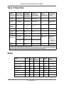
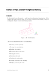
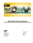
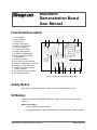
Waveform
Demonstration Board
User Manual
Functional Description
1
2
3
4
5
6
7
8
9
10
11
12
13
14
15
16
17
Power Switch
Power Indicator
Trigger Loop
Injector Type switch
Normal or Glitch switch
Ground connection
Secondary connector
Voltage Potentiometer
Frequency Potentiometer
Duty / Injector Pulse Width
Potentiometer
Ground connection
Sine wave output connection
Variable voltage output connection
Frequency output connection
Variable Frequency and Duty
output connection
Fuel Injector output connection
9V battery connection
1
2
3
4
5
6
7
8
17
16 15 14 13 12
11
10
9
Figure 1: Waveform Demonstration Board outline
Safety Notice
Refer to your equipment manual for safety and warning messages prior to use.
9V Battery
Install the 9V battery (ANSI/NEDA 1604A, IEC, 6LR61) as shown on the board outline
(Figure 1).
Replace the battery:
• If circuit operation becomes erratic.
• If the operating battery voltage drops below 7.0V measured at the battery connector.
©2003 Snap-on Incorporated. All rights reserved.
ZEESX306A Rev. A
1
Waveform Demonstration Board User Manual
Power Switch and Power Indicator
The unit has two power on modes:
• Mode 1—Automatic shut-off
The unit will operate for approximately fifteen minutes.
• Mode 2—Continuous operation
The unit will remain on until the power button is pressed.
Automatic Shut-off Mode
To turn the unit on:
Press the Power switch.
The Power indicator lights.
To turn the unit off:
Press the Power switch at any time.
The Power indicator darkens.
Continuous Operation Mode
To turn the unit on:
Press and hold the Power switch for approximately six seconds.
The Power indicator flashes a code, and then continues with a light flashing-pattern at
the rate of flash one second on, and three seconds off.
To turn the unit off:
Press the Power switch at any time.
The Power indicator stops flashing and darkens.
ZEESX306A Rev. A
2
Waveform Demonstration Board User Manual
Table of Operation
Duty/Injector
Output
Injector Type
Frequency
Pulse Width
Connection switch setting
Potentiometer
Potentiometer
Glitch switch
Voltage
Potentiometer function1
Injector
Single spike
1.6mS to 8.3mS
3.5Hz to 57Hz
N/A
Missing Injector
event
Injector
Double spike
2.9mS to 9.3mS
3.5Hz to 57Hz
N/A
Missing Injector
event
Variable
Frequency
and Duty
N/A
0% to 100%
0Hz to 57Hz
N/A
Frequency
N/A
N/A
Variable
Voltage
N/A
N/A
Sine wave
N/A
N/A
Secondary2
Single spike
1.6mS to 8.3mS
Double spike
Fixed at 1.57mS 415 rpm to 6908 rpm
N/A
No effect
Trigger
N/A
N/A
415 rpm to 6908 rpm
Selects Glitch
type
104 rpm to 1727 rpm N/A
Potentiometer
position:
A – Missing cyl1
B – Missing cyl 2
C – High fire cyl 1
D – Low fire cyl 2
Missing event
1. A Glitch event occurs approximately every 2 seconds.
2. The Secondary output is based on a 4-cylinder vehicle. Synchronization of the Secondary is done in combination
with the trigger output. Synchronize on the trigger when trying to view Secondary faults.
Setup
Signal
Channel
Glitch Volts Per
Time
On/Off Division
Trigger
Frequency
Range
Variable Frequency
CH1
OFF
2.0v
2mS
Pos/2.5
5.3Hz – 950Hz
Variable Frequency /
Variable voltage
CH1
OFF
2.0v
2mS
Pos/2.5
0Hz – 57Hz
Variable Voltage
CH1
ON
1.0V
500mS
Pos/1.0V
N/A
Fuel Injector
CH1
N/A
10.0V
2mS
Neg/10.0V
N/A
Sine wave
CH1
N/A
2.0V
2mS
None
0Hz – 57Hz
Secondary
TBD
TBD
TBD
TBD
TBD
TBD
Trigger
TBD
TBD
TBD
TBD
TBD
TBD
ZEESX306A Rev. A
3
Waveform Demonstration Board User Manual
Usage Tip
To synchronize to the glitches using the variable voltage output:
1. Use a 2-channel scope. Setup the Variable voltage output on the trigger-channel, and
the signal of interest on the remaining channel.
2. Set the variable voltage output to 2.5V, or potentiometer (POT) positioned midway.
3. Setup the trigger-channel for Failing edge, and adjust the threshold to 1.0V.
The threshold voltage will change if you are trying to trigger on secondary glitch
events. This is due to the voltage POT being used to select the event.
4. When a glitch event occurs on the voltage output, the other outputs are glitched as
well. The glitch on the other signals will be somewhere near the actual voltage glitch.
ZEESX306A Rev. A
4