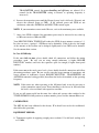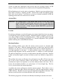
1
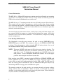
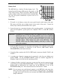
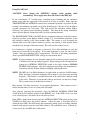
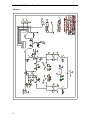
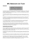
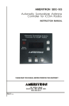
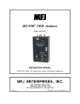
MFJ-969 DELUXE Versa Tuner II
MFJ-969 Versa Tuner II
Instruction Manual
General Information
The MFJ-969 is a 300 watt RF output power antenna tuner that will match any transmitter
or transceiver to virtually any antenna. Peak or average forward and reflected power and
SWR can be read on the illuminated cross-needle meter.
The MFJ-969 uses a "T" matching network and covers all bands between 160 and 6 meters.
This network will tune dipoles, inverted-vees, verticals, mobile whips, beams, random
wires, and many other antennas. The MFJ-969 has rear panel connectors for coaxial, single
wire or two wire feedlines. A built-in 4:1 balun allows the use of balanced open wire,
twinlead, or twin-axial feedlines.
An internal eight position antenna-selector switch selects a built-in 50 ohm dummy load,
two separate coaxial line outputs, or a single wire line-balanced line output. All of these
functions can be selected in tuned (with tuner's "T" network in line) or bypassed (no tuning
circuit) configurations.
Peak Reading SWR/Wattmeter
The illuminated cross-needle meter measures the peak or average FORWARD power,
REFLECTED power, and SWR. The wattmeter is active in all ANTENNA SELECTOR
positions. To use the wattmeter without using the MFJ-969 tuning circuits select one of
the ANTENNA SELECTOR positions under BYPASS.
NOTE: The meter ON/OFF switch must be ON for the meter circuit to function. The
MFJ-969 wattmeter circuit does not function accurately if the Auto Tuner in
your radio is used. To disable the meter, turn the meter ON/OFF switch to the
OFF position. Set the ANTENNA SELECTOR switch to one of the bypass
positions when using the Auto Tuner in your radio.
Peak envelope power (PEP) is measured when the PEAK or AVERAGE METER push
button (right-hand side) in placed in the PEAK (in) position. Peak power and average
power values are equal with steady unmodulated carriers, FSK, or FM. The PEP power is
twice the average power with SSB two tone test modulation. PEP power may be any
amount larger than the average power with SSB voice signals.
The metering circuit in this unit provides very accurate forward peak power readings
during with any form of modulation. Either an internal 9 volt battery for portable
operation, or an external supply can be used to power the peak detector. Current demand is
very low, and the 9 volt battery will last its' shelf life.
1
MFJ-969 DELUXE Versa Tuner II
The 9 volt battery has one disadvantage, it limits meter accuracy at power levels over 250
watts. The 9 volt battery is disconnected when an external supply is used. An external
supply of 11 to 18 volts will permit use of the wattmeter above 250 watts.
The meter's full scale forward and reflected power range is controlled by the left-hand
METER switch. If your transmitter runs more than 30 watts of output power, set this
switch to 300W (in position). If your transmitter has less than 30 watts of output, set this
switch to the 30W switch position (out).
Forward power is displayed on the left-hand FORWARD meter scale. This scale is
calibrated from 0 to 300 watts and is read directly in the 300 watt position. Each picket
(scale mark) represents 25 watts between 300 and 100 watts, 10 watts between 100 and 10
watts, and has a single 5 watt picket below 10.
In the 30W position the forward power scale must be divided by 10. Each picket
represents 1/2 watt below 1 watt, 1 watt from 1 to 10 watts, and 2.5 watts from 10 to 30
watts.
Reflected power is read on the right-hand REFLECTED meter scale. This scale indicates
60 watts full scale when the 300W forward power sensitivity is selected, and 6 watts full
scale when the 30W power sensitivity is selected. This scale has a picket every 5 watts
above 10 watts and at each watt below 10 watts.
The reflected scale is also divided by 10 when using the 30W switch position.
When trying to measure power with a less than perfect match, the reflected power should
be subtracted from the forward power readings. The SWR is read directly from eleven red
SWR curves that range from 1:1 to infinity. SWR is measured by observing the point
where the forward and reflected power needles cross. The SWR is indicated by the red
curve closest to the needle crossing point. No cumbersome or time consuming SWR
sensitivity adjustments are required with this meter.
The wattmeter has an internal lamp that backlights the meter scale. The meter ON / OFF
switch turns the meter lamp off and on and disables or enables the meter circuit. The lamp
circuit requires power from an external 12 Vdc source, such as the optional MFJ-1312D
power supply. The external supply will also supply power for the peak power detector.
The rear panel jack accepts a 2.1 mm coaxial plug with a positive center pin polarity.
Antenna Selector
The ANTENNA SELECTOR switch has eight positions. From counter-clockwise to
clockwise the positions are: DUMMY LOAD, BALANCED or SINGLE WIRE LINE,
COAX 1, and COAX 2 with the tuner matching circuits in line, and the reverse sequence
from COAX 2 back to DUMMY LOAD with the antenna tuning circuits bypassed.
2
MFJ-969 DELUXE Versa Tuner II
Dummy Load
The MFJ-969 has a built-in 50 ohm dummy load. The
internal load will dissipate 300 watts for 30 seconds, or 100
watts for 90 seconds. Power levels above 100 watts require
a three minute cooling off period between transmissions.
The load will operate continuously at power levels of 25
watts or less.
Installation
1. To install a 9 volt battery, remove the access panel located on the bottom of the unit.
The battery will slide into a holder located on the inside of the panel. Connect the
battery snap to battery and reinstall the access panel.
2. Locate the tuner in a convenient location at the operating position. Avoid placing the
tuner near microphones, speech processors, computers, TNC's or other RF sensitive
devices.
WARNING: If random wire or balanced feeders are connected directly to this tuner,
position the tuner so the rear panel terminals can not be accidentally
contacted by persons or conductors. When transmitting with random wire
or balanced lines, the rear panel feed-through insulators can operate with
high RF voltages. These voltages may cause serious RF burns. These
high RF voltages may also damage anything contacting or within a half
inch of the terminals.
3. Install the MFJ-969 between the transmitter and antenna. Use a 50 ohm coaxial cable
to connect the transmitter or transceiver to the SO-239 (UHF female) labeled
TRANSMITTER on the back of the tuner.
4. Coaxial feedlines attach to the SO-239 (UHF female) connectors labeled COAX 1 and
COAX 2.
5. A random wire (longwire) antenna may be connected to the five-way binding post
marked WIRE. See the ANTENNA HINTS section for detailed suggestions on
bringing a single wire feeder into the operating position.
6. A balanced feedline (twin lead, open wire, or twin-axial line) may be connected to the
two binding posts marked BALANCED LINE. Connect a jumper wire from the WIRE
binding post, as indicated by the dotted line on the MFJ-969, to one of the
BALANCED LINE posts. This connection activates the internal 4:1 balun.
NOTE: Do not connect wire and balanced antenna's to the MFJ-969 at the same time,
unless you want to apply power to both antennas at the same time. If a longwire
or single wire feeder is used, be sure to remove the WIRE to BALANCED LINE
jumper connection.
3
MFJ-969 DELUXE Versa Tuner II
Using The MFJ-969
CAUTION: Never change the ANTENNA selector switch position while
transmitting! Never apply more than 300 Watts to the MFJ-969!
In any conventional "T" network tuner, maximum power handling and the smoothest
tuning occurs when the capacitance in the network is as large as possible. In this tuner the
TRANSMITTER and ANTENNA controls have maximum capacitance at position 0 (fully
meshed), and minimum capacitance at position 10 (fully open). Be sure to use the highest
possible capacitance for each band. This will provide the smoothest tuning, highest
efficiency, and greatest power handling capability. The chart in the tuning instructions
shows typical capacitor settings that can be used for each amateur band.
The ROLLER INDUCTOR in the MFJ-969 has maximum inductance in the full counterclockwise position (at the highest number, around 117), and minimum inductance in the
full clockwise rotation (at the lowest number, 000). The counter is reset by turning the
inductor knob to the full counter clockwise position, and pushing a small pointed object
into the hole to the right of the turns counter. This will reset the counter to zero.
Less inductance is required as frequency is increased. If too little inductance is used, the
tuner may not match the load properly. If too much inductance is used, the tuner will be
"touchy" and power handling will be compromised. The chart in the tuning instructions
shows typical ROLLER INDUCTOR settings for each amateur band.
NOTE: If your transmitter uses an adjustable output circuit it must be properly tuned into
a 50 ohm load at the operating frequency. Proper tuning can be accomplished by
placing the ANTENNA SELECTOR switch in the fully clockwise BYPASS
DUMMY LOAD position. Adjust the transmitter according to the manufacturer's
instructions into the 50 ohm dummy load before adjusting the tuner.
NOTE: The MFJ Air Core Roller Inductor is designed with an exclusive Self-Resonance
Killer that keeps potentially damaging self-resonances away from your operating
frequency. This feature is switched in and out of the circuit wiht a built-in switch
in the roller. Therefore as you turn the roller up and down, you may feel a bump.
This is normal and you should not be alarmed.
Most modern solid state transceivers do not require adjustments. If the transceiver has a
built in antenna tuner, be sure it is turned off or disabled.
After properly preparing the transmitter, place the MFJ-969 ANTENNA SELECTOR
switch in the desired antenna position in the BYPASS area. If the SWR is low (very little
or no reflected power), the tuner can be left in this position.
If the SWR is higher than desired, place the ANTENNA SELECTOR switch in the proper
TUNED area that selects the desired antenna. Adjust the tuner as described below to
obtain the best SWR. Do NOT change the transmitter's tuning (plate) or loading (antenna)
controls until after the tuner has been fully adjusted. The transmitter can be "touched up"
(if necessary) after the MFJ-969 is fully tuned.
4
MFJ-969 DELUXE Versa Tuner II
Adjustment Procedure
When using the MFJ-969 in receive only applications, adjust the MFJ-969 for the
highest "S" meter or signal level. The Tuning Chart can be used as a starting reference.
To use the MFJ-969 for transmitting, follow the steps below:
1. Select the 30W (out) METER switch scale. Place the PEAK AVG button in the AVG
(out) position. Turn the transmitter's power control fully down.
2. Position the TRANSMITTER and ANTENNA controls and the INDUCTOR
SELECTOR switch in the bottom Tuning Chart position for the operating frequency.
Tuning Chart
Freq. MHz
1.8
1.9
2.0
3.6
3.9
7.15
10.15
14.15
18.2
21.1
24.9
28.5
50.2
Transmitter
1
1
1
1
2
4-1/2
6
6-1/2
7
8
8-1/2
9
9-1/2
Antenna
1
1
1
1
2
4-1/2
6
6-1/2
7
8
8-1/2
9
9-1/2
Inductor
33
41
47
91
93
107
112
116
118
119
119
121
123
3. Apply just enough power on CW (or AM / FM / RTTY) to obtain noticeable deflection
on the reflected power meter.
4. Carefully adjust the ROLLER INDUCTOR and ANTENNA controls for the lowest
reflected power.
NOTE: These controls interact. Adjust the ROLLER INDUCTOR for minimum SWR,
then adjust the ANTENNA control for minimum SWR. Go back and forth
between these adjustments as many times as required until the lowest reflected
power (best SWR) is obtained.
5. If a perfect or very low SWR can not be obtained, try moving the TRANSMITTER
control to a slightly higher setting. Repeat from Step 3.
NOTE: Always use the lowest setting of the TRANSMITTER control that allows a
match. The widest matching range occurs at higher numerical settings of the
5
MFJ-969 DELUXE Versa Tuner II
TRANSMITTER control, but power handling and efficiency are reduced. (It is
normal for the TRANSMITTER setting to advance as operating frequency is
increased.)
6. Increase the transmitter power until the Forward power level is full scale (30 watts) and
observe the reflected power or SWR. If the reflected power and SWR are not
satisfactory, adjust the ANTENNA and INDUCTOR controls again.
NOTE: If your transmitter can not reach 30 watts, set it to the maximum power available.
7. After a low SWR is obtained, the transmitter power may be increased to any value up
to 300 watts carrier or 300 watts PEP.
Your DELUXE VERSA TUNER II will reduce the SWR of most antenna systems to 1:1.
In a few rare cases, a perfect 1:1 SWR may not be obtainable. If this is the case, the length
of the antenna or the feedline can be changed slightly until a low SWR can be obtained.
See the antenna hints section.
In Case Of Difficulty
If this tuner fails to tune, please double check all connections and follow the tuning
procedures again. Be sure you are using enough inductance (a higher ROLLER
INDUCTOR number) and have the capacitors open far enough (a higher front panel
number).
If this tuner arcs at the rated power levels, please double check all connections and follow
the tuning procedures again. Be sure you are using the largest amount of capacitance and
lowest amount of inductance (lowest ROLLER INDUCTOR, TRANSMITTER and
ANTENNA numerical setting possible) that allows the load to be matched on the operating
frequency.
NOTE: If this tuner arcs when operating on the 160 meter band, it may be necessary to
reduce transmitter output power. Power handling is the lowest on 160, and when
the load is a low resistance with capacitive reactance.
If you are still unsuccessful, but the tuner does adjust and operate when switched to the
TUNED DUMMY LOAD position or another antenna, please read the Antenna Hints text.
CALIBRATION:
The MFJ-969 has been calibrated at the factory. IF it should ever need to be recalibrated,
then follow this procedure:
EQUIPMENT NEEDED:
1. Transmitter capable of supplying enough power to obtain 1/2 to full scale reading at 14
or 21 MHz.
6
MFJ-969 DELUXE Versa Tuner II
2. 50 Ohm dummy load that is capable of handling full power that the transmitter can put
out and has better than a 1.15:1 swr.
3. A power meter of known accuracy. The calibration will only be as good as the
reference meter.
4. 50 Ohm cables capable of handling the power. RG-58/U is recommended. DO NOT
USE RG-59 or RG-11.
METER CALIBRATION -- refer to PC layout for trimpot location.
PC BOARD should identify the trimpots as: HIGH FORWARD, LOW FORWARD,
HIGH REFLECT, LOW REFLECT.
1. Remove the top cover of the MFJ-969.
2. Connect the equipment as shown in the diagram below. Use 50 Ohm dummy load for
the antenna. Set the transmitter to 14 MHz band.
3. Transmit about 100 Watts as indicated on the reference meter. Adjust
LOW
FORWARD to set 100 Watts on the forward power scale. Next set the pushbuttons to
the 2000 Watt power scale. Transmit 1000 Watts as indicated on the reference meter.
Adjust HIGH FORWARD to set 1000 Watts on the forward scale.
4. To set the reflected power, interchange the transmitter and coax cable so that the
transmitter is connected to the antenna connector and the dummy load is connected to
the transmitter connector. Set the range switch to the 200 Watt range. Transmit 10
Watts as indicated on the reference meter and adjust LOW REFLECT to indicate 10
Watts on the reflected scale of the MFJ-969. Next set the range switch to the 2000 Watt
scale. Transmit 100 Watts according to the reference meter and adjust HIGH
REFLECT to indicate 100 Watts on the reflected scale.
5. SWR requires no calibration.
Grounding Hints
To minimize RFI, single wire feedlines (such as used with Windom or longwire antennas)
should be kept away from other wiring. Radiation will be minimized if the single wire
feeder runs parallel and reasonably close to the wire that connects the tuner to the outdoor
ground. The antenna feed wire should be adequately insulated to prevent arcing or
accidental contact.
For safety, please use both dc and RF grounds. It is particularly important to have a good
RF ground while using a single wire feeder. When using a single wire feeder, the tuner
needs something to "push" against in order to force current into a single wire feedline. If a
good RF ground is not available, RF will usually find it's way back into the power line
(RFI), transmitter audio circuits (RF feedback), or the operator (RF burns).
Water pipes and ground rods provide good dc and ac safety grounds, but they are often
inadequate for RF grounding because they are single conductors. RF grounds work much
better when "spread out" over a large area with multiple connections directly to the
equipment ground point. Water pipes, heating ducts, and fences may work (especially if
they are all connected together with jumper wires), but the best RF grounds are radial
7
MFJ-969 DELUXE Versa Tuner II
systems or multi-wire counterpoises that provide large low resistance surfaces for RF
energy. Ground rods by themselves are almost useless for dependable RF grounding.
RF and lightning travels on the surface of conductors. Braided or woven conductors have
high surface resistance to lightning and RF. Ground leads for RF and lightning should
have wide smooth surfaces. Avoid the use of woven or braided conductors in RF and
lightning grounds unless the lead needs to be flexible.
Antenna Hints
WARNING: For operator safety a good outside earth ground or water pipe ground
should ALWAYS be installed and connected to the case of the MFJ-969.
Make certain the safety ground also connects to the transmitter and other
station accessories. A wing nut post marked GROUND is provided for
ground connection(s).
Location
For the best performance, an end-fed longwire wire antenna should be at least one quarterwavelength long at the operating frequency. Horizontal antennas should be at least a half
wave long and high and clear of surrounding objects. While good RF grounds help the
signal in almost any transmitting installation, it is extremely important to have good RF
grounds with long wire or other Marconi antennas.
Matching Problems
Most matching problems occur when the antenna system presents an extremely high
impedance to the tuner. When the antenna impedance is much lower than the feedline
impedance, an odd quarter-wavelength feedline converts the low antenna impedance to a
very high impedance at the tuner. A similar problem occurs if the antenna has an
extremely high impedance and the transmission line is a multiple of a half-wavelength.
The half-wavelength line repeats the very high antenna impedance at the tuner. Incorrect
feedline and antenna lengths can make an antenna system very difficult or impossible to
tune.
This problem often occurs on 80 meters if an odd quarter-wave (60 to 70 foot) open wire
line is used to feed a half-wave (100 to 140 foot) dipole. The odd quarter-wave line
transforms the dipole's low impedance to over three thousand ohms at the tuner. This is
because the mismatched feedline is an odd multiple of 1/4 wavelength long. The line
inverts (or teeter-totters) the antenna impedance.
A problem also occurs on 40 meters with this antenna example. The feedline is now a
multiple of a half-wave (60 to 70 foot) and connects to a full-wave high impedance antenna
(100 to 140 foot). The half-wave line repeats the high antenna impedance at the tuner. The
antenna system looks like several thousand ohms at the tuner on 40 meters.
The following suggestions will reduce the difficulty in matching an antenna with a tuner:
8
MFJ-969 DELUXE Versa Tuner II
1. Never center feed a half-wave multi-band antenna with a high impedance feedline that
is close to an odd multiple of a quarter-wave long.
2. Never center feed a full-wave antenna with any feedline close to a multiple of a halfwave long.
3. If a tuner will not tune a multi-band antenna, add or subtract 1/8 wave of feedline (for
the band that won't tune) and try again.
4. Never try to load a G5RV or center fed dipole on a band below the half-wave design
frequency. If you want to operate an 80 meter antenna on 160 meters, feed either or
both conductors as a longwire against the station ground.
To avoid problems matching or feeding any dipole antenna with high impedance lines,
keep the lines around these lengths. The worst possible line lengths are shown in
brackets:
160 meter dipole; 35-60, 170-195 or 210-235 feet.
(Avoid 130, 260 ft)
80 meter dipole; 34-40, 90-102 or 160-172 feet.
(Avoid 66, 135, 190 ft)
40 meter dipole; 42-52, 73-83, 112-123 or 145-155 feet. (Avoid 32, 64, 96, 128 ft)
Some trimming or adding of line may be necessary to accommodate higher bands.
WARNING: To avoid problems, a dipole antenna should be a full half-wave on the
lowest band. On 160 meters, an 80 or 40 meter antenna fed the normal
way will be extremely reactive with only a few ohms of feedpoint
resistance. Trying to load an 80 meter (or higher frequency) antenna on
160 meters can be a disaster for both your signal and the tuner. The best
way to operate 160 with an 80 or 40 meter antenna is to load either or
both feedline wires (in parallel) as a longwire. The antenna will act like a
"T" antenna worked against the station ground.
9
MFJ-969 DELUXE Versa Tuner II
Technical Assistance
If you have any problem with this unit first check the appropriate section of this manual. If
the manual does not reference your problem or your problem is not solved by reading the
manual, you may call MFJ Technical Service at 662-323-0549 or the MFJ Factory at 662323-5869. You will be best helped if you have your unit, manual and all information on
your station handy so you can answer any questions the technicians may ask.
You can also send questions by mail to MFJ Enterprises, Inc., 300 Industrial Park Road,
Starkville, MS 39759; by Facsimile (FAX) to 662-323-6551; or by email to
[email protected].
Send a complete description of your problem, an
explanation of exactly how you are using your unit, and a complete description of your
station.
10
MFJ-969 DELUXE Versa Tuner II
Schematic
11
MFJ-969 DELUXE Versa Tuner II
NOTES
12