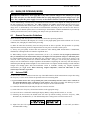
1
HF/VHF SWR Analyzer
Model MFJ-259C
INSTRUCTION MANUAL
CAUTION: Read All Instructions Before Operating Equipment
MFJ ENTERPRISES, INC.
300 Industrial Park Road
Starkville, MS 39759 USA
Tel: 662-323-5869 Fax: 662-323-6551
VERSION C1
COPYRIGHT
C
2013 MFJ ENTERPRISES, INC.
MFJ-259C Instruction Manual
HF/VHF SWR Analyzer
TABLE OF CONTENTS
1.0 INTRODUCTION........................................................................................................................................ 1
1.1
A Quick Word about Accuracy................................................................................................. 1
1.2
Typical Uses ............................................................................................................................ 2
1.3
Frequency Range ..................................................................................................................... 2
2.0 POWER SOURCES ..................................................................................................................................... 2
2.1
External Power Supply............................................................................................................. 3
2.2
Using Internal Batteries ........................................................................................................... 3
2.3
Using Rechargeable “AA” Type Batteries ................................................................................ 3
2.4
Using Conventional “AA” Drycell Batteries............................................................................. 4
2.5
“Power Saving” Mode (sleep mode) ......................................................................................... 4
3.0 MAIN MENU AND DISPLAY .................................................................................................................... 4
3.1
General Connection Guidelines................................................................................................ 4
3.2
Power-up Display..................................................................................................................... 5
3.3
Main MODE descriptions ........................................................................................................ 5
3.4
Blinking “VOLTAGE LOW” display warning ......................................................................... 6
4.0 MAIN (OR OPENING) MODE.................................................................................................................... 7
4.1
General Connection Guidelines................................................................................................ 7
4.2
Antenna SWR.......................................................................................................................... 7
4.3
Coax Loss ................................................................................................................................ 9
4.4
Capacitance ............................................................................................................................. 9
4.5
Inductance ............................................................................................................................... 10
5.0 ADVANCED OPERATION......................................................................................................................... 11
5.1
Forward ................................................................................................................................... 11
5.2
General Connection Guidelines................................................................................................ 12
5.3
(Magnitude of) Impedance mode.............................................................................................. 12
5.4
Return Loss and Reflection Coefficient mode ........................................................................... 13
5.5
Distance to Fault mode ............................................................................................................ 13
5.6
Resonance Mode...................................................................................................................... 14
5.7
Percentage Transmitted Power ................................................................................................. 14
6.0 ADJUSTING SIMPLE ANTENNAS............................................................................................................ 14
6.1
Dipoles .................................................................................................................................... 14
6.2
Verticals .................................................................................................................................. 15
6.3
Tuning a simple antenna.......................................................................................................... 15
7.0 TESTING AND TUNING STUBS AND TRANSMISSION LINES ............................................................. 16
7.1
Testing Stubs ........................................................................................................................... 16
7.2
Velocity Factor of Transmission Lines ..................................................................................... 16
7.3
Impedance of Transmission Lines or Beverage antennas .......................................................... 17
7.4
Adjusting Tuners ..................................................................................................................... 18
7.5
Adjusting Amplifier Matching Networks ................................................................................. 18
7.6
Testing RF Transformers ......................................................................................................... 19
7.7
Testing Baluns......................................................................................................................... 19
7.8
Testing RF Chokes................................................................................................................... 20
8.0 TECHNICAL ASSISTANCE ....................................................................................................................... 20
ii
MFJ-259C Instruction Manual
1.0
HF/VHF SWR Analyzer
INTRODUCTION
Attention: Read Section-2.0 before attempting to use your analyzer. Incorrect power
supply voltages or excessive external voltage applied to the Antenna connector will
damage it!
Description
The MFJ-259C is a compact battery powered RF impedance analyzer that combines four basic circuits; a 50-ohm
bridge, eight-bit micro-controller, frequency counter, and a 0.53-230 MHz variable-frequency oscillator with
switched coverage of nine overlapping bands. These four sub-elements are integrated to provide a wide variety of
useful antenna and impedance measurements including coaxial cable loss and distance to an open or short.
Although designed primarily for analyzing 50-ohm antennas and transmission line systems, the MFJ-259C also
measures RF impedance from a few ohms to several hundred ohms. In addition, it functions as a discrete signal
source (RF-Signal Generator) and independent frequency counter.
1.1
A Quick Word about Accuracy
Inexpensive impedance meters have limitations. The main causes of measurement error are:
(1.) Signal ingress from external RF sources
(2.) Component limitations
(3.) Stray reactance from connectors, pc traces, and wires.
1.) Signal Ingress: Virtually all low-cost handhelds use simple broadband diode detectors. Unlike costly lab-grade
analyzers using frequency-selective receivers, broadband detectors admit out-of-band signals. Unfortunately, the
offending interference can't be filtered out using common low-pass or band-pass circuitry because the L/C elements
would act like lengths of transmission line and transform the impedance readings as a function of frequency.
Increasing generator power output can, in some instances, overpower interfering signals, but the current needed to
deliver the additional RF power greatly reduces battery life. In fact, over 70% of the analyzer's 150-mA current
drain is already allocated to the VFO and its amplifier stages for generating a low-harmonic level-amplitude test
signal.
Most RF-interference problems occur at lower frequencies and are caused by high-power AM-broadcast stations.
These signals couple efficiently into large antenna arrays and are especially problematic for 160-meter verticals. In
the event you encounter intense local interference, we recommend using the MFJ-731 Tunable Analyzer Filter. It
is designed to attenuate off-frequency signals between 1.8 and 30 MHz without introducing significant errors.
2.) Component Limitations: At very low voltage levels, diode detectors become nonlinear, a condition that
reduces accuracy. The MFJ-259C minimizes this problem by using special microwave zero-bias Schottky detectors
with linearity enhanced by compensating diodes. Using this technique, each analyzer is individually optimized to
provide the highest accuracy possible with both high and low impedance loads, making the A/D converter's 8-bit
resolution the analyzer's primary accuracy limitation.
3.) Stray Reactance: The length of electrical connections between components within the bridge circuit, and the
line between the bridge and antenna connector, may introduce inaccuracy at higher frequencies and when the load
impedance is very high or very low. However, the MFJ-259C minimizes this problem with careful pc layout and by
using low-capacitance microwave-grade surface-mount components with virtually no lead length.
While some analyzers may display misleading "exact readings" falling outside the reliable measurable range, the
MFJ-259C does not. Instead, it is programmed to generate a display warning for out-of-range results. For example,
if (Z > 650) appears on your display, it means the impedance being measured is greater than 650 ohms and outside
the reliable measurement range.
1
MFJ-259C Instruction Manual
1.2
HF/VHF SWR Analyzer
Typical Uses
The MFJ-259C may be used to adjust, test, or measure the following:
Antennas:.......................................SWR, impedance, reactance, resistance, resonant frequency, and bandwidth
Antenna tuners: ............................SWR, bandwidth, frequency
Amplifiers: .....................................Input and output matching networks, chokes, suppressors, traps, and
components
Coaxial transmission lines:........SWR, length, velocity factor, approximate Q and loss, resonant frequency,
and impedance
Filters:.............................................SWR, attenuation, and frequency range
Matching or tuning stubs: ..........SWR, approximate Q, resonant frequency, bandwidth, impedance
Traps:..............................................Resonant frequency and approximate Q
Tuned Circuits: .............................Resonant frequency and approximate Q
Small capacitors:..........................Value and self-resonant frequency
RF chokes and inductors: ..........Self resonant frequency, series resonance, and value
Transmitters and oscillators:.....Frequency
The MFJ-259C measures and displays the following:
Cable length (feet)
Cable Loss (dB)
Capacitance (pF)
Impedance or Z magnitude (ohms)
Impedance phase (degrees)
Inductance (uH)
Reactance or X (ohms)
Resistance or R (ohms)
Resonance (MHz)
Return loss (dB)
Signal Frequency (MHz)
SWR (referenced to 50 ohms)
The MFJ-259C as a non-precision signal source:
VFO output is leveled at approximately 3-Vpp, or around 20 milliwatts into a 50-ohm load. This signal is
relatively pure with harmonics better than -25 dBc (dB below the fundamental-frequency carrier). The internal
source impedance (Zo) is 50 ohms.
A more complete description of the MFJ-259C's features along with proper measurement methods can be found by
reading sections covering the particular measurement you wish to make. Consult the table of contents for various
applications.
1.3
Frequency Range
The MFJ-259C covers 0.53 to 230 MHz without frequency gaps using a precision reduction-drive VFO tuning
capacitor and two band switches. Bands of coverage are:
Main Switch: 155-230 MHz 113-155 MHz
Lower Range Switch:
4.7-11 MHz
67-113 MHz
28-67 MHz
11-28 MHz
2.1-4.7 MHz
1.0-2.1 MHz
0.53-1.0 MHz
Lower Range
To select the bands above 11 MHz, turn the Main Switch to the band desired. For the bands below 11 MHz, turn
the Main Switch to Lower Range and select the desired band using the Lower Range switch.
2.0
POWER SOURCES
Please read this entire section before connecting your analyzer to any power source. Improper
connections or incorrect voltages may cause permanent damage to your analyzer!
2
MFJ-259C Instruction Manual
2.1
HF/VHF SWR Analyzer
External Power Supply
MFJ offers an optional power supply, the MFJ-1312D, that satisfies all external supply requirements. We
strongly recommend using this supply. If you use a different power source, note that the voltage output must be
greater than 11 volts and less than 16 volts when the analyzer is powered on and running (loaded power source).
The maximum voltage in Sleep Mode (unloaded power source) should never exceed 18 volts. AC adapters must be
well filtered and the plug must have a grounded sleeve and positive center lead. The ideal voltage-source
specification is 14.5 VDC at 150 mA. Confirm your supply can deliver this output level safely without overheating
or introducing excessive AC ripple.
Please read the battery installation instructions (Section 2.3) if you plan to install batteries. Never connect
external DC power if non-rechargeable batteries are installed and the battery charger is enabled. Permanent
damage could result!
+
-
+
2.1 mm
The MFJ-259C has a recessed 2.1 mm power jack located on the top-right-hand side of the unit. It is labeled Power
13.8 VDC. The jack's outside barrel contact is negative and the center pin is positive. Inserting a power plug into
the power jack automatically disables the internal batteries as a power source. However, the batteries will be
trickle charged if the charger circuit is enabled.
IMPORTANT WARNING: Reverse Polarity Or Excessive Voltage Can Damage Or Destroy The MFJ-259C.
Never Apply More Than 18 Volts, Never Use AC-output or Positive Ground Supplies!
2.2
Using Internal Batteries
Before installing batteries for the first time, check the position of the Charger Jumper. To gain access, remove the
eight screws securing the analyzer's back cover and separate it from the unit. Look for a 3-pin header with a small
black-plastic shorting plug that fits over two of its pins. It is located at the top of the main pc board near the OFFON switch and power connector. The shorting plug must be properly positioned for the type of battery you intend
to use (either rechargeable or non-rechargeable). While you have the analyzer's case removed, you may install
batteries into their tray -- or install them later by removing the battery-tray door that is attached to the rear of the
case with two screws.
2.3
Using Rechargeable “AA” Type Batteries
IMPORTANT WARNING: Do not use an external power sources that deliver less than 13.8 volts with
rechargeable batteries installed. If the external supply voltage is too low, the charger will not work properly and
batteries will eventually discharge. We recommend charging batteries with the MFJ-259C power switch off and
allowing enough charging time to establish full battery charge. A minimum of ten hours is recommended.
When using rechargeable batteries, your power source must deliver a minimum of 13.8 volts to meet the minimum
charge-voltage threshold. Typical charging current is 10-20 mA (trickle-charge rate). The charger circuit functions
any time external power is connected, even when the analyzer is turned off. Again, the MFJ-1312D supply fulfills
all power supply and charging requirements for the MFJ-259C and is recommended.
When using rechargeable batteries, the internal black plastic jumper must be set to the proper position. If it is
not set properly, the batteries will not charge. As described above, the jumper is located inside the analyzer, near
the external power jack on the back side of the circuit board.
For rechargeable batteries, set the jumper as shown below:
3
MFJ-259C Instruction Manual
2.4
HF/VHF SWR Analyzer
Using Conventional “AA” Drycell Batteries
Whenever possible, install a fresh matched set of high-quality alkaline batteries. Conventional zinc cells will work,
but alkaline batteries offer a lower risk of damage caused by leakage. Alkaline cells also provide longer running
time and superior shelf life. When using any non-rechargeable dry-cell battery, always remove them immediately
when they become weak to avoid damage from leakage. Also, never store your analyzer for extended periods
(longer than a month) with non-rechargeable batteries installed.
IMPORTANT WARNING: When Using Non-Rechargeable Batteries, The Analyzer's Internal Charging System
Must Be Defeated! To Defeat The Charger, Set The Internal Jumper To The Charger-Off Position, As Shown
Below:
2.5
“Power Saving” Mode (sleep mode)
The analyzer's current drain is normally around 150 mA, which places a moderate demand on the battery pack.
You can extend the analyzer's running time significantly by using the internal Sleep Mode power-saving function.
In Sleep Mode, the analyzer's RF-generator shuts down and battery drain drops to under 15 mA. Any time Sleep
Mode is activated, the analyzer operates with a two-minute inactivity window. During any 2-minute period, you
must actuate the Mode switch -- or adjust the frequency by more than 50 kHz -- at least once for the analyzer to
remain awake. Any time a two-minute inactivity period elapses, the power saving circuit automatically switches in.
When the analyzer goes to sleep, a blinking SLP message will appear in the display’s lower right corner, as shown
below:
To reawake the unit, momentarily press either the Mode or Gate button.
To Disable Sleep mode:
(1.) Turn the analyzer off.
(2.) Press and hold the Mode button while reapplying power.
(3.) Continue holding the Mode button until the copyright message appears on the screen.
(4.) Release Mode. If Sleep Mode was disabled successfully, the message shown below will appear on-screen. The
Sleep Mode function becomes re-enabled anytime the analyzer is turned Off and On again.
3.0
MAIN MENU AND DISPLAY
IMPORTANT WARNING: Never Apply RF or any other external voltage to the Antenna port of this
unit. The MFJ-259C uses zero bias detector diodes that may be damaged by external voltages. Read
Section-2.0 before applying power! Incorrect supply voltages will also damage this unit.
3.1
General Connection Guidelines
1.) Antenna Jack: When making RF measurements, connect your Device Under Test (DUT) to the SO-239
connector located on the top of the case. You'll use this port for SWR and all other RF measurements excluding the
Frequency Counter function.
4
MFJ-259C Instruction Manual
HF/VHF SWR Analyzer
2.) Power connector: (2.1 mm type) is described in Section 2.0. Be sure to read Section-2.0 before operating your
unit. Using an incorrect power sources can permanently damage the analyzer.
3.) Frequency Counter Input: BNC connector used for frequency-counter functions only.
3.2
Power-up Display
After turning on the Power switch (or after applying external power with the switch on), a sequence of three
message screens appear on the display.
The first screen presents the analyzer's software version (VER).
MFJ-259C
VER 13.40
The second message shows the software copyright symbol.
MFJ-Enterprises
(c)
The third message provides a power-source check, displaying the internal battery or external power supply voltage
level along with a warning if the source is too low to support reliable operation.
The fourth and final power-up display is the working screen for the analyzer’s default operating mode, as described
in Section 3.2 (SWR, Impedance R&X). The two analog panel meters also become active, displaying SWR and
Impedance Magnitude (Z) measurements for the DUT.
The MFJ-259C has five (5) Basic Operating Modes that are used for conducting a variety of measurements. If you
tap (momentarily press) the Mode button, the analyzer steps to the next Mode selection. The five main modes and
their opening screens are described in Section-3.3 below:
3.3
Main MODE descriptions
Press the Mode switch to scroll through the analyzer's five operating modes. By "scrolling", we mean that each tap
of the mode switch will step the analyzer ahead to the next menu selection. Each new selection comes up on the
display with an Identifier Screen. After 3 seconds, the Identifier Screen is replaced by the mode's working screen.
The menu is circular, so after sequencing through all five choices, the sequence starts over. The five basic
operating modes are described in detail below:
1.) Impedance R&X (Initial Mode): Use this mode for measuring SWR and complex impedance. The Impedance
R&X mode is the analyzers "default" mode because it is the one most frequently used for routine antenna
adjustments. The top line of the working display shows the VFO Frequency in MHz and the numerical SWR
reading. The lower line displays the Resistive (R) and Reactive (X) impedance components for the attached
load. Pressing and holding the Gate button in this mode displays the Impedance Magnitude (Z) and Phase
Angle (Ø). The analog Impedance meter also displays Impedance Magnitude (Z), and the SWR meter displays
Standing Wave Ratio (SWR). The analog meters are especially useful when tuning continuously adjustable
circuits such as an ATU or matching networks. The identifier screen for the Impedance R & X mode is shown
below:
5
MFJ-259C Instruction Manual
HF/VHF SWR Analyzer
2.) Coax Loss: Use the analyzer's second mode to measure loss incurred in random lengths of 50-Ohm cable, 50Ohm attenuator pads, 50-Ohm transformers, and 50-Ohm baluns. The top working-display line shows the
VFO Frequency in MHz and the lower line presents the measured Loss in dB. Note that the transmission line
or device under test must be unterminated at its far end during loss testing. If a load or resistive
termination is installed, the measured loss will be significantly higher than the actual loss. Note that this
measurement mode only works for lines or devices carrying differential currents.
3.) Capacitance in pF: Use this mode for checking unknown capacitor values (in pF) and for determining how
much reactance a component exhibits at a particular frequency (Xc in ohms). In Capacitance Mode, the top
line of the working display shows the VFO Frequency in MHz and the measured Capacitive Reactance (Xc) at
the VFO frequency (in ohms). The lower line shows the measured capacitance (C) in picofarads (pF). The
analog Impedance meter also displays Xc reactance in ohms.
4.) Inductance in uH: In Inductance Mode, the top line of the working display shows the VFO Frequency in MHz
and the capacitive reactance (XL) at the VFO frequency (in ohms). The lower line shows the measured
inductance (L) in microhenries (µH). The Impedance meter displays reactance in ohms.
5.) Frequency Counter: The fifth mode converts the analyzer into a discrete frequency counter. Connect the RF
source (DUT) to the BNC connector labeled Frequency Counter Input. As with many counters, the sensitivity
threshold for a locked-in reading gradually decreases with increasing frequency. The measurement threshold
at 0.53 MHz is around 10 millivolts -- and this level gradually increases to around 200 millivolts at 230 MHz.
The "never exceed" limit for safe testing is 2-volts peak-to-peak. The counter's default gate time is 0.1
second, but you may reset it to either .01 second (very fast) or 1.0 second (very slow) by tapping the Gate
button. A 1.0-second gate times provide increased frequency resolution (more digits to the right of the decimal
point), and the .01 gate provides very fast response with less resolution (see sample screens below):
IMPORTANT WARNING: Never apply more than two volts of peak voltage -- or any dc voltage -- to
the Frequency Counter BNC port.
3.4
Blinking “VOLTAGE LOW” display warning
If the external dc source or battery voltage drops below 11 volts, a blinking Voltage Low warning will come up on
the display. Pressing Mode during a low-voltage warning will disable it and allow you to continue testing.
Caution: Measurements made with supply voltages below 11 volts may not be as reliable.
6
MFJ-259C Instruction Manual
4.0
HF/VHF SWR Analyzer
MAIN (OR OPENING) MODE
IMPORTANT WARNING: Never apply RF or any other external voltages to the Antenna port of this
unit. This unit uses zero bias detector diodes that are easily damaged by external voltages over a few
volts. Also, confirm the power supply is correct, as described in Section-2.0, before operating this unit.
A basic understanding of antenna theory and transmission line behavior will be helpful for making the best use of
the data provided by your MFJ-259C. The ARRL Handbook and ARRL Antenna Book provide concise peerreviewed explanations that should suffice for most applications. When it comes to the finer points of antenna
design, there is (unfortunately) a fair amount of mis-information circulating on the web and over the airwaves.
When it comes to antenna systems, there's no black magic. Stick with the scientific fundamentals as presented by
credible professional sources, and everything your analyzer tells you should make sense!
4.1
General Connection Guidelines
When conducting SWR and Impedance measurements, follow these practical guidelines:
1.) If connector transitions (RF adapters) are needed, use only high-quality parts and check them over for wear,
oxidation, dirt, and tight pin contact before proceeding.
2.) Make all connection electrically secure and keep all leads as short as possible. This precaution is especially
important when measuring electrical components that are not part of a 50-ohm coaxial system.
3.) Always use good quality 50-ohm cable and connectors when making SWR measurements. Contaminated,
mismatched, or damaged cable will introduce significant error.
4.) When making Complex Impedance measurements, (R+X) or (Z), remember that any length of transmission
line you install between the load and the analyzer will displace the load from the analyzer's calibration plane.
For simple handheld analyzers like the MFJ-259C, the calibration plane is always located at the analyzer's RF
connector. This is the point where Zo=50 Ohms and Phase shift = 0 degrees. It is the only test point where the
analyzer will be calibrated for complex impedance measurements. Displacing the load away from the analyzer's
calibration plane through random lengths of coax will have little or no impact on SWR readings, but will introduce
enough error through phase shift and transformer action to invalidate virtually any complex impedance
measurement you might make! When measuring Complex Impedance, install the MFJ-259C as close
(electrically) to the DUT as possible!
4.2
Antenna SWR
Use the SO-239 Antenna connector located on top of the MFJ-259B for all RF measurements (except those using
the Frequency Counter mode). Follow the procedure below for measuring SWR:
1.) If your antenna doesn't have a dc-grounded feed system, momentarily short the cable's center conductor to
the shield immediately before connecting it to the analyzer. This simple procedure will discharge any static
buildup on the antenna and prevent damage to the analyzer's sensitive detector diodes.
2.) Connect the antenna lead to the analyzer's SO-239 Antenna connector.
3.) Set the VFO's two Frequency selector band switches to the appropriate range.
4.) Turn on the Power switch while watching the display. Battery voltage should read OK (11-16 volts).
5.) Following the boot screens, the default mode will come up with the working screen for Frequency, SWR,
Resistance (R), and Reactance (X). The SWR and Impedance analog meters will also become active.
6.) Adjust Tune (the VFO capacitor) as needed to find your desired test frequency -- or tune until you obtain a
minimum SWR reading.
7
MFJ-259C Instruction Manual
HF/VHF SWR Analyzer
Note that the MFJ-259C also has Advanced antenna-measurement modes that are described in Section-5.0.
However, unless you have a strong working knowledge of RF systems, you may find these added modes of limited
value. Most represent more technical ways of expressing the same data offered by the basic modes.
Antenna hints:
1.) Measuring Antenna Impedance: For complex impedance measurements, you must install the analyzer as
close as possible to the element's feed point (within or 1-2 degrees of phase shift) or use a precisely cut 1/2wavelength of cable displace the calibration plane by a controlled amount (360-degree phase rotation).
2.) Electrical Half-Wavelengths of Cable: Installing a half-wavelength of cable between the load and the
analyzer will rotate phase a full 360 degrees so that no apparent transformation takes place in the line.
However, the response will only be transparent on one discrete frequency. Even a small frequency change will
begin to skew your impedance readings and may even shift the antenna's resonant frequency because the cable
will begin to introduce its own reactance into the system. Errors will compound with multiple halfwavelengths, so limit cable to one or two phase rotations at most!
3.) SWR, Resonance, and Impedance: It's always preferable to measure SWR rather than resonance or
impedance magnitude (Z) as the standard for adjusting your antenna. By definition, minimum SWR (1:1)
and maximum power transfer occur when the source, transmission line, and load impedance are all of equal
value. Resonance occurs when reactance fully cancels at the antenna's feed point and the load becomes purely
resistive (Xc+XL=0). Although Minimum SWR and Resonance often coincide closely, they are not directly
correlated and rarely occur on exactly the same frequency. If your antenna doesn't happen to present a 50-ohm
load at resonance, there will still be resistive mismatch in the system and lower SWR may actually occur on
some other frequency. By the same token, if you adjust your antenna for an Impedance reading of 50 ohms, the
load could have a substantial reactive component (e.g. R=46, X=17) that elevates SWR and shifts the
minimum-SWR point to a different frequency. SWR is always your best predictor of antenna performance!
4.) Tuning and Matching: Unlike simple wire dipoles, many antennas such as Yagis and verticals are adjustable
for both resonant frequency and impedance match. Begin by setting these antennas for the element length
prescribed in the instruction sheet -- or the calculated length. Then, adjust the matching network for minimum
SWR. The two adjustments (tuning and matching) are separate but often interact, so be prepared to alternately
readjust both element length and network setting to achieve minimum SWR at your exact frequency of
interest.
5.) Adding and Removing Feedline: You should be able to add or remove lengths of feedline (or measure SWR at
any point along the feedline) without observing a significant change in SWR. It is normal to see SWR drop
slightly as cable is added, or see it increase slightly as cable is removed because of changes in resistive loss.
However
(a.) if your SWR measurements change a lot with relatively small changes in cable length, or
(b.) SWR changes as the cable is moved around, or
(c.) SWR changes when the coax shield is grounded at some point part way between the antenna and the
radio, look for a feed problem!
Here are some possibilities to check:
6.) Common Mode Current: Your coax may be carrying Common-Mode Current on its outer shield and radiating
RF. To eliminate this problem, install a Guanella current balun at the feed point. It will isolate the shield from
the radiating portion of the antenna, stabilize SWR, reduce receiver noise, and suppress "RF in the shack".
Installing a balun is good engineering practice -- and always worth doing!
7.) Defective Cable: Your coax may not really be 50 ohms. Kinks, water ingress, oxidation, corrosion, bad
connectors, improper manufacturing, poor quality, or even mislabeling may be the cause. Check SWR with a
dummy load installed at the far end of the cable. If the SWR is elevated or the Impedance (Z) fluctuates very
much as you tune the analyzer's VFO, suspect defective cable.
8
MFJ-259C Instruction Manual
HF/VHF SWR Analyzer
8.) Excessive Transmission Line Loss: Your cable may exhibit unusually high losses caused by damage or
contamination. Or, it may simply have too much normal attenuation for the frequency range where you're
using it (especially true at VHF). To look for unacceptably high loss, unterminate the cable at its far end and
use the analyzer’s Coax Loss mode to check it against specified values.
4.3 Coax Loss
Access the analyzer's Coax Loss mode by stepping the Mode switch to the Coax Loss identification screen. The top
line of the working screen displays Frequency in MHz and the lower line shows Coax Loss in dB. Note that the
Impedance meter is disabled in this mode. Coax Loss was designed to measure losses in 50-ohm cables, but also
effectively measures the differential-mode loss in many types of 50-ohm transmission-line transformers, choke
baluns, and 50 ohm attenuator pads.
CAUTION: Do not measure conventional transformers, or attenuators and coaxial cables that are not 50 ohms.
When making measurements, the opposite end of the device under test must have an open circuit, a short
circuit, or a pure reactance for termination. Any loss resistance will make attenuation appear worse than it
actually is.
To measure loss:
1.) Connect the 50-ohm cable, attenuator, transmission line type balun, or transformer under test to the Antenna
connector. Confirm the distant end of the DUT isn't terminated by a resistance.
2.) Turn the analyzer ON and toggle the Mode switch once to the Coax Loss Screen.
3.) Tune the analyzer's VFO to the frequency where you wish to measure loss. The loss in dB will be displayed for
any specific frequency you select between 0.53 and 230 MHz.
4.4
Capacitance
Access the Capacitance Mode by stepping the Mode switch to the Capacitance identification screen. The top line
of the working display shows the Frequency in MHz and the Capacitive Reactance (Xc) of the DUT at that specific
frequency. The lower line displays the computed Capacitance in pF. Normally, the measurement range is from a
few pF to a few thousand pF. The MFJ-259C becomes inaccurate when measuring reactance below 7 ohms or
above 650 ohms. If reactance falls into the inaccurate range, C(X<7), C(X=0), or C(Z>650) will be displayed.
Capacitance values are not displayed when the measurement accuracy is questionable (see examples below):
Finding the Reactance Sign:
The MFJ-259C measures the DUT's reactance (X) and mathematically converts it to a capacitance value. However,
the analyzer's processor can't determine if the reactance it measures is actually inductive or capacitive. You can
usually determine the type of reactance by adjusting the VFO frequency. If you tune up in frequency and reactance
(X) on the display or meter decreases, the load is capacitive (-j) at the measurement frequency. If you tune down in
frequency and reactance decreases, the load is inductive (+j) at the measurement frequency.
9
MFJ-259C Instruction Manual
HF/VHF SWR Analyzer
To measure a capacitor:
1.) Turn on the analyzer and toggle the Mode switch twice to bring up the Capacitance identification screen.
2.) Connect the capacitor across the Antenna connector with the shortest leads possible, or include the lead length
normally used in the actual circuit to include stray lead inductance in your measurement.
3.) Adjust the VFO to your frequency of interest. If a range warning comes up, find the closest frequency where no
warning appears. Warnings are C(Z>650), C(X<7), and C(X=0). The C(X=0) warning indicates the capacitor
appears as a near-perfect short.
When measuring a capacitor, it's displayed value in pF will typically change with the test frequency. The change
occurs because stray inductance inside the capacitor and in the wires leading to the calibration plane are in series
with it. The actual value (in pF) for most capacitors does increase with frequency and may reach infinity when the
capacitive element and its stray inductance become series-resonant. This frequency is called the device's Series
Resonant Frequency (where X=0). Bypass capacitors are sometimes intentionally operated at or near this
frequency, but for most applications, the frequencies will be far below it. In addition to the display, the analyzer's
Impedance meter displays the reactance (X in ohms) of the capacitor.
4.5
Inductance
Access the Inductance mode by stepping the Mode switch to the Inductance identification screen. The top line of
the working display shows the VFO Frequency in MHz and the Inductive Reactance (XL) of the DUT at that
particular frequency. The lower line shows the Inductance in uH. Inductance is calculated using the measured
Reactance (XL) and the VFO frequency. The MFJ-259C will become inaccurate when measuring reactance below
7 ohms or above 650 ohms. If component reactance falls into an inaccurate range, L(X<7) L(X=0) or L(Z>650) will
be displayed. No inductance value is displayed if the range is questionable.
Positive Reactance Sign:
The MFJ-259C measures Reactance (X) and mathematically converts it to an Inductance value, but its processor
can't determine if the reactance is inductive or capacitive. You can usually determine the type (or sign) of the
reactance by adjusting the VFO. If tuning up in frequency cause the reactance to decrease, the load is likely
capacitive (-j) at the measurement frequency. If tuning down in frequency causes the reactance to decrease, the
load is likely inductive (+j) at the measurement frequency.
To measure an Inductor:
1.) Turn the analyzer on and step the Mode switch three times to bring up the Inductance identification screen.
2.) Connect the inductor (DUT) across the Antenna connector using the shortest leads possible, or with the lead
length normally used in your working circuit to include stray inductance in the measurement.
3.) Adjust the VFO to your frequency of interest. If an error sign comes up, choose the nearest frequency where no
warning appears. The L(X=0) warning indicates the inductor looks like a near perfect short to the analyzer's
10
MFJ-259C Instruction Manual
HF/VHF SWR Analyzer
bridge and the frequency is too low (or the inductor too small) to measure. The digital display and the analog
Impedance meter both present the DUT's reactance (X) in ohms.
When measuring an inductor, its displayed value will sometimes change with the test frequency. This happens
because of stray capacitance between coil windings and in the leads going to the Antenna connector. At RF, the
value of an inductor (in uH) may appear substantially different from its "rated" value that was determined at a
lower frequency. With increasing frequency, measured inductance usually increases and, at some high frequency,
the coil may become self-resonant and appear as an open circuit (or a trap) with infinite reactance. At some very
low frequency, it may look like a short.
5.0
ADVANCED OPERATION
To access the Advanced Mode, press and hold the Gate and Mode buttons simultaneously for several seconds.
When you release, the Advanced message appears on-screen. The Advanced Menu features the following modes:
Impedance. .............................................. SWR, impedance magnitude, phase angle of impedance
Return Loss and Reflection Coefficient..... SWR, return loss, impedance, reflection coefficient
Distance to fault ....................................... SWR, impedance, and distance to fault
Resonance ............................................... SWR, resistance and reactance
Transmit efficiency ................................... SWR, Impedance, Forward power as percentage of apparent power
5.1
Forward
In Advanced Mode, the MFJ-259C measures:
(1.) Distance to Fault,
(2.) Impedance Magnitude,
(3.) Reactance,
(4.) Resistance,
(5.) Standing Wave Ratio (SWR).
It also converts basic SWR data into alternative parameters such as Return Loss, Reflection Coefficient, Match
Efficiency, Transmission Loss, and Percentage of Apparent Power in the system (see equivalency chart below). All
of these terms have a corresponding SWR value attached to them, so if they seem unfamiliar and you have no
specific need to apply them, sticking with basic SWR measurements will serve you just as well!
11
MFJ-259C Instruction Manual
HF/VHF SWR Analyzer
MFJ-259C Limitations for Advanced Measurements:
The analyzer's coupler uses a 50-ohm bridge with voltage detectors across each leg. An eight-bit microcontroller
processes these voltages and applies formulas to derive useful information from them. The basic calculations are
Resistance, Reactance, SWR, and Complex Impedance. In accuracy challenged modes, the system crosschecks
itself and presents a weighted average of the most reliable information. The overall resolution of the system is
limited by eight-bit A/D conversion while some of the formulas contain square-law and higher-order functions. As
a result, some data jumping may occur at the edges of a least-significant-bit. The resolution of the analyzer's
compensated detector is accurate to about 0.5 %, and to minimize the opportunity for error, we use the most direct
calculations possible.
Technical Resources:
As suggested previously, if you wish to delve in and acquire a deeper understanding of electromagnetics and
transmission line theory or the associated vocabulary, it's always best to choose sources that have been peerreviewed and edited by professional RF-design engineers. Not all of the casually posted information you'll read
online or hear over the airwaves meets high standards of technical reliability!
5.2
General Connection Guidelines
As before, use the Antenna connector for all RF-measurement except those in Frequency Counter mode. During
testing, the analyzer's VFO (or "stimulus generator") delivers about +7 dBm of RF output (around 0.5 V-RMS),
and appears like a 50 ohm source resistance. The unterminated (open circuit) voltage increases to approximately 1
volt RMS. Harmonics are better than -25 dBc over the VFO operating range. While the VFO is not frequency
stabilized, it is useful as a discrete signal source for many applications. Also, note that the Antenna connector is not
dc-isolated from the load, so any external bias voltage will couple directly to the internal detectors diodes and
potentially damage them.
IMPORTANT WARNING: Never apply external voltages or RF signals to the antenna connector. Protect this
port from ESD.
Again, use secure RF connections, and keep leads short as possible when measuring components or systems other
than Zo=50 ohms. Also, assume that installing a random-length transmission line between the DUT and the
analyzer's calibration plane can and usually will substantially alter Impedance measurements. When measuring
SWR, use properly constructed 50-ohm coaxial cables of known quality and check connector condition.
5.3
(Magnitude of) Impedance mode
Impedance Magnitude is the first measurement mode in the advanced menu. The MFJ-259C also allows you to
view Impedance Magnitude from the basic-menu SWR/Impedance R&X mode by simply pressing the Gate key. In
Advanced Mode, the identification screen for Impedance Magnitude is shown below:
The working display presents the VFO frequency, Impedance Magnitude in ohms, and the Phase Angle ( θ ) in
degrees. The analog meters also indicate SWR and Impedance. The maximum impedance limit for this mode is set
at 650 ohms, as indicated by the (Z<650) message:
Stray Connector Capacitance: The 4.4-pF stray capacitance contributed by the analyzer's SO-259 connector will
not affect HF measurements and produce only minor errors for Impedances readings at VHF. Error will be most
pronounced at 230 MHz.
12
MFJ-259C Instruction Manual
5.4
HF/VHF SWR Analyzer
Return Loss and Reflection Coefficient mode
From Advance Mode, open the Return Loss and Reflection Coefficient display by tapping Mode one time. The
identification screen is shown below:
On the working screen, the VFO frequency and SWR are displayed on the top line, while the bottom line presents
the equivalent Return Loss (in dB) and the Voltage Reflection Coefficient (ρ). The analog meters display SWR and
impedance.
5.5
Distance to Fault mode
From Advance Mode, enter Distance to Fault by tapping Mode twice. The identification screen is shown below:
This mode is useful for finding the physical or electrical length of a random piece of cable, or for finding the
distance to a transmission line fault. Unbalanced lines need not be isolated during testing and may be coiled on the
floor. For balanced lines (ladder line, open-wire feeders, etc), run the MFJ-259C on internal batteries and keep it
at least a few feet away from earth and other conductors. Attach only the DUT (no other wires) -- one lead to the
center pin of the Antenna connector and the other to the case via the grounding stud. Suspend two-wire balanced
feeder in a straight line so it remains clear of metallic objects and ground by at least a few feet.
The Distance to Fault test measures the electrical distance to the transmission line's abnormality. To obtain the
physical distance, multiply electrical distance times the feed line’s specified Velocity Factor (Vf). For example, if
the analyzer display reads DTF = 75 feet and the transmission line is typical RG-8 with a specified velocity factor
of 0.66, the physical distance to the fault will be: 75 x .66 = 49.5 feet.
An open or a short-circuit at the fault yields best accuracy -- some resistive and reactive loads or L/C terminations
may skew the results or simply not work. To conduct the test, follow the specific sequence of steps outlined below.
To measure fault distance:
1.) Connect the DUT to the analyzer's Antenna connector. From Advanced mode, tap the Mode switch twice to
bring up the Distance to Fault ID screen. The top line of the working screen will display the VFO frequency in
MHz followed by 1st blinking at a rapid rate. The 1st indicates the analyzer is waiting for entry of the first
X=0 frequency. The lower line displays DTF (no data showing) and X with the Reactance reading in ohms.
2.) Begin by searching for the lowest VFO frequency where the Impedance meter shows a sharp null and where the
reactance value on the screen approaches zero (X=0). If possible, find an exact frequency where X=0:
21.324 MHz 1st
DTF
X=0
3.) When you've found the first X=0 null, tap the Gate button once to enter it. The blinking 1st will change to a
blinking 2nd. Now, tune to the next higher X=0 null. A minimum reading of a few ohms is acceptable if the X
display won't zero.
42.648 MHz 2nd
DTF
X=1
13
MFJ-259C Instruction Manual
HF/VHF SWR Analyzer
4.) Press Gate again, and the display will indicate the DTF. Multiply the DTF times the velocity factor of the cable
(Vf) to get the physical DTF (distance in feet).
Dist. to fault
11.3 ft x Vf
5.6
Resonance Mode
From the Advanced menu, tap the Mode switch three times to bring up the Resonance Mode ID screen. The top
line of the working screen displays the VFO frequency in MHz followed by SWR. The lower line displays
Resistance (R) and Reactance (X). Resonance Mode functions exactly the same as in the analyzer's basic SWR
mode, except the analog impedance meter measures Reactance rather than impedance magnitude. This feature
allows the operator to more easily observe frequencies where system reactance crosses zero. When Reactance
equals zero (X=0), all capacitive and inductive components at the load are cancelled out (XL+Xc=0) and the
circuit is said to be Resonant.
Accuracy Note:
As previously discussed in Section 4.2, when measured thro feedline, readings indicating zero reactance (or
resonance) may appear at frequencies where the antenna itself isn't actually resonant. Conversely, the antenna may
appear to exhibit some reactance even at its true resonant frequency. To ensure measurement accuracy, the
analyzer's calibration plane should always be located as close to the DUT (or as close to 0-degrees of phase
rotation) as possible.
5.7
Percentage Transmitted Power
From the Advanced screen, toggle the Mode button four times to open Percentage of Transmitted Power. This
parameter is yet another way of representing the basic SWR measurement (see chart at 5.1). Mathematically, it is
an inverse presentation of the Percentage of Reflected Power scale. If your load measures 3.1:1 SWR, the
Percentage of Reflected Power in the system will be 26%. By subtracting 26% from 100%, the Percentage of
Transmitted Power is 74% (see examples below).
1.8963 MHz 3.1
Power = 74 % SWR
50.097 MHz 1.3
Power =98% SWR
29.538 MHz >25
Power< 15% SWR
Note that the Percentage of Transmitted Power may be open to misinterpretation because the power ultimately
absorbed into the load may be significantly different than the raw Percentage of Transmitted Power parameter
might suggest.
6.0
ADJUSTING SIMPLE ANTENNAS
Most antennas are tuned for operating frequency by varying the element length -- and most homemade verticals
and dipoles are very simple to adjust.
6.1
Dipoles
Because the dipole is a balanced antenna, it's always a good idea (and good engineering practice) to install a balun
at the feed point. A balun could be as simple as several turns of coax wrapped several inches in diameter or it could
be a complicated affair with many windings on a ferromagnetic core. A 1:1 Guanella "current" balun wound on a
toroid core made from material with the appropriate permeability is usually the most effective choice.
14
MFJ-259C Instruction Manual
HF/VHF SWR Analyzer
The height of a dipole above ground, as well as any surrounding objects, will influence the feed point impedance
and SWR. Typical residential heights usually result in minimum SWR readings below 1.5:1 when using 50-ohm
coaxial cable. In general, the only adjustment available for tuning a simple wire dipole is its length. If too long, it
resonates too low in the band. If too short, it resonates high. You may be able to improve the match (SWR) by
raising or lowering the element in relationship to ground. However, doing so may impact other parameters such as
the best take-off angle for distant or local contacts (TOA).
Anytime the antenna impedance and feedline impedance do not precisely match each other (as is usually the case),
the feedline will act like a transformer and modify the Impedance of the load placed at the opposite end. However,
if you use good-quality 50-ohm cable, the SWR should remain constant except for a small reduction caused by
resistive loss as the line is made longer. If changing the coax length by a relatively small amount changes SWR at
your test frequency, the feedline either has common-mode current flowing on the outer surface of the shield that is
detuning the antenna, or the feedline itself is not really 50-ohm cable. Common-mode current caused by
conduction typically occurs when no balun has been installed at the feed point to choke it off. Common-mode
induction currents may also result from other installation errors such as running the feedline parallel rather than
perpendicular to the radiating element. Repositioning the feedline may reduce unwanted inductive coupling.
6.2
Verticals
Verticals in the "monopole" class require a ground plane. To simplify installation and cut costs, manufacturers
sometimes (incorrectly) downplay the importance of an effective radial system. When installed over a good ground,
the impedance of a quarter-wave radiator may be quite low, with SWR running nearly 2:1. Ironically, over a poor
ground, minimum SWR for the same antenna could improve to 1:1. However, if the ground system is poor,
antenna performance will be compromised despite favorable SWR readings. Far better to install the best ground
system possible and configure a matching network at the base of the vertical element to match into a 50-ohm feed
system. Verticals tune the same as dipoles -- add length to lower the operating frequency and shorten to raise it.
Another class of verticals are considered "ground-independent" because they come with a counterpoise or rigid
radial system built into the design. These antennas are usually configured as multiband OCFDs (off-center fed
dipoles) with the longer leg being the dominant vertical radiator. Ground independent verticals tend to work more
efficiently when elevated well above ground rather than when installed in close proximity to it because of reduced
ground losses. Many use multiple resonators or traps and have a matching network at the feed point. Most groundindependent vertical elements are asymmetrical and require a highly effective baluns to prevent the feedline from
becoming part of the antenna system.
6.3
Tuning a simple antenna
To tune a basic dipole fed with 50-ohm coax, follow the steps outlined below:
1.) Momentarily short the center conductor and shield to bleed off static, then connect to the Antenna jack.
2.) Set the analyzer's band switches and VFO tuning for the desired band.
3.) Select any analyzer operating mode that will display SWR.
4.) Read the SWR and adjust the VFO tuning for minimum SWR. Write down the frequency.
5.) To re-tune your antenna accurately without a lot of cut-and-try, calculate a Scaling Factor.
6.) First, determine if the antenna needs to be shorter (higher in frequency) or longer (lower in frequency).
7.) To make it shorter ( higher), divide the present frequency by the desired frequency (scaling factor <1).
8.) To make it longer (lower), divide the desired frequency by the present frequency (scaling factor >1).
9.) Multiply the scaling factor by the present length to calculate the new length.
For example, suppose your 132-foot dipole has low SWR on 3.750 MHz and you want to move it to 3.900 MHz. It
needs to be shorter to tune higher, so you calculate the scaling factor: 3.750/3.900 = 0.96. Next calculate the new
length: 132 feet x .96 = 126.7 feet. Note that scaling only applies to full-size verticals and dipoles that don't use
loading coils, traps, stubs, resistors, capacitors, or capacitance hats. Antennas with these features should be
adjusted according to the manufacturer’s instructions.
15
MFJ-259C Instruction Manual
HF/VHF SWR Analyzer
7.0
TESTING AND TUNING STUBS AND TRANSMISSION LINES
7.1
Testing Stubs
To measure Resonant Frequency for a matching stub or transmission line, select the SWR/Impedance mode in the
Basic Menu (opening mode). Note that DUTs measuring 1/4λ and odd multiples (1/4λ, 3/4λ, 5/4λ, etc) are
terminated with an open circuit at the far end. DUTs measuring 1/2λ and even multiples (1λ, 1-1/2λ, 2λ) are
terminated with a short circuit.
Coaxial lines may be piled or coiled on the floor and the analyzer operated on external power. Coax lines are
connected to the analyzer's SO-239 connector with the shield grounded. For balanced line, run the analyzer on its
internal batteries, keep it a few feet away from other conductors and earth, and do not attach any stray wires (other
than the feedline itself). Connect the DUT with one lead to the analyzer's ground stud and the other lead to the
Antenna connector center pin. The DUT must be suspended and kept away from metallic objects and ground. When
tuning frequency-critical stubs, trim them gradually using the method outlined below:
1.) Determine the DUT's target frequency and calculate the length to formula.
2.) Cut the DUT 20% longer than your calculated length.
3.) At the far end, install a short for 1/2λ and even multiples -- or leave it open for 1/4λ and odd multiples.
4.) Tune VFO to find the frequency of the lowest Impedance null. To fine-tune the null, watch the Reactance (X)
digital display and adjust as close to zero as possible. If your calculations were correct and the feedline Vf
accurate, the null frequency should be about 20% below your target frequency -- reflecting the 20% in added
length.
Continuing:
5.) Divide the present frequency by the desired frequency to calculate a Scaling Factor.
6.) Multiply the Scaling Factor by the feed line’s present physical length to find the desired physical length.
7.) Cut the stub and confirm that the reactance null (X=0) is on the desired frequency.
7.2
Velocity Factor of Transmission Lines
To determine the Velocity Factor (Vf) of a transmission line, select the Distance to Fault mode by entering the
Advanced menu and pressing Mode twice. The opening screen is shown below:
Coaxial lines may be piled or coiled on the floor and the analyzer can be operated on external power. Coax lines
are connect to the analyzer's SO-239 connector with the shield grounded. For balanced line, run the analyzer on its
internal batteries, keep it a few feet away from other conductors and earth, and do not attach any stray wires (other
than the feedline). Connect the DUT with one lead to the analyzer's ground stud and the other to the Antenna
center pin. The DUT must be suspended and kept away from metallic objects and ground.
Note that the far end of the line may be terminated with an open circuit or a short circuit, but should not be
terminated by any other impedance or resistance value.
To compute Velocity Factor, you must measure both the electrical length (DTF) and the physical length of the
line. Velocity factor is calculated by dividing the physical length by the electrical length. For example, if the
analyzer displays an electrical length of 75 feet and the physical length measures 49.5 feet, the velocity factor will
be: Vf = 49.5 / 75 = 0.66.
To check reliability, make two or more groups of measurements using different starting frequencies spaced at least
one octave apart. If measured distances agree, your result is confirmed. The more frequencies you use for
confirmation, the greater your assurance that the results are correct.
16
MFJ-259C Instruction Manual
HF/VHF SWR Analyzer
To measure velocity factor:
1.) Connect the DUT and tune the analyzer VFO to a frequency where the analog Impedance meter nulls and
where reactance displayed on the screen approaches or crosses zero (X=0).
2.) Tap Gate once to enter your first X=0 frequency. The blinking 1st will change to a blinking 2nd.
3.) Tune the analyzer higher (or lower) in frequency until the Impedance meter reads the next null and the display
again crosses zero. If you can't obtain X=0, then a minimum of a few ohms is acceptable.
4.) Tap Gate again, and the display will show electrical distance in feet.
5.) Using a tape measure, find the physical length of the DUT in feet.
6.) Divide your physical length measurement by the electrical length to calculate Vf.
For example, if you measure 27 feet of cable and the DTF mode displays 33.7 feet, divide physical length (27) by
electrical lenght 33.7 feet: Vf = 27/33.7 = 0.80. Note that Velocity Factor (Vf) may also be expressed as Velocity of
Propagation (Vp). Velocity of Propagation is an equivalent term expressed as a percentage (Vp = 80%).
7.3
Impedance of Transmission Lines or Beverage antennas
This procedure will show you how to measure the impedance of transmission line ranging from a few ohms to 650
ohms directly -- and also how to measure even higher-impedance lines using a broadband transformer or resistance
to extend the analyzer's range. To measure the necessary parameters, use the analyzer's default SWR -- Resistance
(R) and Reactance (X) Mode augmented by the Impedance Magnitude function (access by pressing and holding the
Gate switch).
Methodology:
When random-length transmission line is terminated by a load of the same impedance, no transformation occurs
between the cable's near end and far end. However, as soon as a mismatch is introduced at one end, the impedance
transforms to a value higher or lower than the line's characteristic impedance at the opposite end. If viewed on a
Smith Chart, the transformed impedance would literally trace a circle around the characteristic impedance of the
transmission line with every 360-degree phase shift. The greater the mismatch in ohms, the greater the amplitude
(or diameter) of the circle. We can use this behavior to determine the impedance of an unknown line. Taking one
approach, we intentionally introduce a resistive mismatch at the far end of the line, measure the impedance
transformation over a 360 phase rotation at the near end, and calculate the impedance at the center. Or, we
introduce different trial loads of known resistance at the far end until we find a value where the cable becomes
"flat" across a wide range of frequencies. In essence, we create a circle and then shrink it down until only the
center remains.
As recommended for other transmission line tests, coaxial cable may be piled or coiled on the floor and the
analyzer operated on internal or external power. For balanced line, run the analyzer on internal batteries, keep it
away from other conductors or earth, and don't attach stray wires other than the DUT. Connect the balanced DUT
with one lead to the analyzer's ground stud and the other to the Antenna center pin. The DUT must be suspended
and kept a few feet away from metallic objects and ground. Beverage antennas must be connected directly to the
analyzer.
17
MFJ-259C Instruction Manual
HF/VHF SWR Analyzer
Line Impedance Using an Intentional Mismatch:
The test resistance should be somewhere near (but different from) the line's anticipated impedance. When choosing
a resistance value, consider the limits of the analyzer's measurement range (7 - 650 ohms) and stay well within it.
1.) Connect the DUT to the Antenna connector.
2.) Terminate the far end of the DUT with a non-inductive test resistance.
3.) Tune VFO to the lowest frequency where the Impedance and Resistance indicators both null.
4.) Fine tune to find where X is closest to 0 and R is at its minimum value (null).
5.) Press Gate to confirm θ = 0°. Write down the Resistance (R) value as R1.
6.) Tune up in frequency to find a distinct Impedance peak. Once again, X should approach or equal 0.
7.) Fine tune for the highest Resistance (R) value and confirm θ = 0°. Record Resistance (R) as R2.
8.) Multiply R1 x R2 and find the square root of the product. The result is the line's characteristic impedance.
Example: R1 = 37 ohms. R2 = 66 ohms. 37 x 66 = 2442. The square root = 49.42 ohms.
Line Impedance Using a Potentiometer or Resistor Decade Box:
Limit these measurements to the HF region because stray reactance from a potentiometer or decade box could
become a significant source of error at VHF frequencies. Also, use only non-inductive resistances (no wire-wound
resistors). If needed, you may install a broadband transformer of know performance accuracy to extend the
measurement range.
1.) Connect the DUT to the Antenna connector.
2.) Terminate the far end with a potentiometer or resistance decade box.
3.) Adjust the analyzer's VFO frequency and note only the SWR change (SWR need not be low).
4.) Adjust termination resistance until SWR remains constant over the widest possible range.
5.) The resistance of the termination resistor is the line impedance (or surge impedance of the system).
7.4
Adjusting Tuners
Use a short patch cable to connect the analyzer's Antenna jack to the tuner's 50-ohm input. This connection may
also be made with a manual RF switch to facilitate rapid changeover, provided the switch has >50-dB port
isolation. When using any in-line switch, make sure there is no possible way for the transmitter and the analyzer to
become inadvertently connected!
Important Warning: Always connect the common (rotary contact) of the external RF switch to the tuner. The
switch must connect either the MFJ-259C or the station transceiver to the tuner. Transmitting equipment must
never be configured in a manner where it could accidentally become connected to the MFJ-259C.
1.) Patch the analyzer Antenna jack to the tuner input connector.
2.) Connect the desired antenna at the tuner output connector.
3.) Tune the analyzer VFO to the desired frequency and leave it there.
4.) Select the analyzer's basic SWR, Resistance (R), Reactance (X) Mode.
5.) Adjust the tuner's controls until the analyzer's SWR indicators show unity (1:1).
6.) Turn off and disconnect the MFJ-259C. Re-connect the tuner to the transmitter.
7.5
Adjusting Amplifier Matching Networks
To use the MFJ-259C for testing and adjusting RF amplifiers or other matching networks without applying
operating voltages, see the instructions below. Note that all tubes and other components should be left in position
and connected so that all sources of stray capacitance will remain unchanged.
18
MFJ-259C Instruction Manual
HF/VHF SWR Analyzer
To measure input circuits: Install a non-inductive resistor equaling the approximate driving impedance of each
individual tube between the cathode of each tube and the chassis.
To measure tank circuits: Install a resistor equal to the tube's calculated operating impedance from the anode to
the chassis using short leads.
The antenna relay (if internal) may be engaged using a small external power supply. Closing the relay will connect
the amplifier’s external RF input and output connectors to the amplifier’s internal RF-matching networks. The
appropriate network may now be adjusted. When the analyzer reads 50 ohms and 1:1 SWR at the operating
frequency with the proper amounts of capacitance to set the system Q, the networks are functioning properly.
Caution: The driving impedance of most amplifiers will change as the input drive level is varied. Do not attempt
to adjust the input network with the tube in an operating condition using the low level of RF generated by the
MFJ-259C stimulus generator!
7.6
Testing RF Transformers
The MFJ-259C can test any RF transformer presenting a 25-100 ohm termination on one of its windings. Connect
the 25-100 ohm winding to the analyzer's Antenna jack using a very short 50-ohm pigtail (<1° phase shift). The
other winding (or windings) should be terminated with a low-inductance resistor equal to the desired load
impedance. Sweep the analyzer's VFO across the DUT's intended operating range. Use the basic SWR, Resistance
(R) Reactance (X) Mode (plus the Impedance Magnitude [Z] option) to evaluate the DUT's impedance and useable
bandwidth. You may also measure the transformer's efficiency by comparing the source voltage generated by the
MFJ-259C to the load voltage using standard power-level conversions.
7.7
Testing Baluns
To test balun performance, connect the analyzer Antenna jack to the balun's 50-ohm unbalanced input. Terminate
the balanced side with two equal-value load resistors connected in series to make up the required load impedance.
For example, to test a 200-ohm (4:1) secondary, use a pair of 100-ohm carbon (non-inductive) resistors in series, as
shown below in Fig A:
Fig A
A
50 Ohms
Unbal
Balun
Fig B
R1
B
C
50 Ohms
Unbal
Balun
R2
Clip Lead
>
R1
A
<
C
R2
Clip Lead
A properly designed current balun works best for maintaining current balance. It also has the highest power
capability and lowest loss for given materials. To evaluate the balun (DUT), measure SWR while connecting the
grounded clip lead to point A, B, and C. When functioning properly, a current balun will exhibit low SWR over its
entire operating range with the clip lead installed at any of those three positions.
A well designed voltage balun should show low SWR over its operating range with the clip lead installed at
position B, but show poor SWR with the clip lead is installed at A or C (note, however, that the SWR readings
should measure about the same whether connected to A or C). A voltage balun should also be tested using the
configuration shown in Fig B, with the resistors in parallel. If it is operating properly, SWR will be remain low
with the resistors connected from either output terminal to ground.
19
MFJ-259C Instruction Manual
7.8
HF/VHF SWR Analyzer
Testing RF Chokes
For testing self-resonance in chokes, use the analyzer in basic SWR, Resistance (R) + Reactance (X) Mode. Large
RF chokes often have frequencies where distributed capacitance and inductance form a low impedance seriesresonance. Series resonance occurs because the choke winding acts like a succession of back-to-back L networks.
This condition can potentially result in three problems:
1.) The end-to-end Impedance of the choke becomes very low.
2.) The voltage at the center of the resonant point becomes very high, often causing severe arcing.
3.) The current in the winding becomes very high, often resulting in severe heating.
To detect troublesome series resonance, install the choke in its designated operating location and connect the
analyzer in an end-to-end configuration through a short 50-ohm jumper cable (with no other connections). Slowly
sweep the choke's operating range looking for impedance dips that identify low-impedance series-resonant
frequencies. When detected, move a small insulated screwdriver blade along the choke to find a point where the
series-resonate impedance changes suddenly. This is the region that has the highest voltage present, and the area
where adding or subtracting even a tiny amount of capacitance had the greatest effect. To shift the resonance out of
the desired frequency range, try removing turns to reduce capacitance -- or adding a capacitive stub. A small
change in capacitance has a much more impact than making a small change in inductance because the ratio of L to
C is so high.
8.0
TECHNICAL ASSISTANCE
If you have any problem with your MFJ-259C, first check the appropriate section of this manual. If the manual
does not reference your problem and the problem isn't solved by reading the manual, you may call MFJ Technical
Service at 662-323-0549 or the MFJ Factory at 622-323-5869. We can serve you best if you have your unit,
manual, and all pertinent information about your difficulty handy so you can answer questions the technicians may
ask.
You can also send questions by mail to:
MFJ Enterprises, Inc.,
300 Industrial Park Road,
Starkville, MS 39759;
by FAX to 662-323-6551; or by e-mail to [email protected]. Send a complete description of your
problem, an explanation of exactly how you are using your unit, and a complete description of your station.
20
FULL 12-MONTH WARRANTY
MFJ Enterprises, Inc. warrants to the original owner of this product, if manufactured by MFJ Enterprises,
Inc. and purchased from an authorized dealer or directly from MFJ Enterprises, Inc. to be free from defects
in material and workmanship for a period of 12 months from date of purchase provided the following terms
of this warranty are satisfied.
1. The purchaser must retain the dated proof-of-purchase (bill of sale, canceled check, credit card
or money order receipt, etc.) describing the product to establish the validity of the warranty claim
and submit the original or machine reproduction of such proof of purchase to MFJ Enterprises, Inc.
at the time of warranty service. MFJ Enterprises, Inc. shall have the discretion to deny warranty
without dated proof-of-purchase. Any evidence of alteration, erasure, of forgery shall be cause to
void any and all warranty terms immediately.
2. MFJ Enterprises, Inc. agrees to repair or replace at MFJ's option without charge to the original
owner any defective product provided the product is returned postage prepaid to MFJ Enterprises,
Inc. with a personal check, cashiers check, or money order for $12.00 covering postage and
handling.
3. MFJ Enterprises, Inc. will supply replacement parts free of charge for any MFJ product under
warranty upon request. A dated proof of purchase and a $8.00 personal check, cashiers check, or
money order must be provided to cover postage and handling.
4. This warranty is NOT void for owners who attempt to repair defective units. Technical
consultation is available by calling (662) 323-5869.
5.
This warranty does not apply to kits sold by or manufactured by MFJ Enterprises, Inc.
6. Wired and tested PC board products are covered by this warranty provided only the wired
and tested PC board product is returned. Wired and tested PC boards installed in the owner's
cabinet or connected to switches, jacks, or cables, etc. sent to MFJ Enterprises, Inc. will be returned
at the owner's expense un-repaired.
7. Under no circumstances is MFJ Enterprises, Inc. liable for consequential damages to person or
property by the use of any MFJ products.
8. Out-of-Warranty Service: MFJ Enterprises, Inc. will repair any out-of-warranty product
provided the unit is shipped prepaid. All repaired units will be shipped COD to the owner. Repair
charges will be added to the COD fee unless other arrangements are made.
9.
This warranty is given in lieu of any other warranty expressed or implied.
10. MFJ Enterprises, Inc. reserves the right to make changes or improvements in design or
manufacture without incurring any obligation to install such changes upon any of the products
previously manufactured.
11. All MFJ products to be serviced in-warranty or out-of-warranty should be addressed to MFJ
Enterprises, Inc., 300 Industrial Park Rd, Starkville, Mississippi 39759, USA and must be
accompanied by a letter describing the problem in detail along with a copy of your dated proof-ofpurchase and a telephone number.
12. This warranty gives you specific rights, and you may also have other rights, which vary from
state to state.
Rev 04/08/2011
MFJ ENTERPRISES, INC.
300 Industrial Park Road
Starkville, MS 39759
MFJ-259C Manual
Version C1
Printed In U.S.A.