1
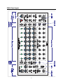
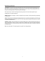
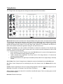
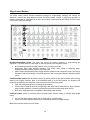
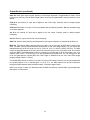
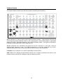
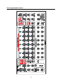
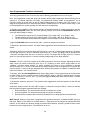
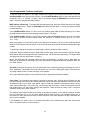
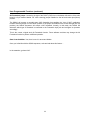
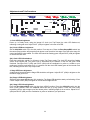
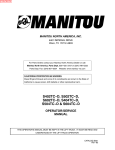
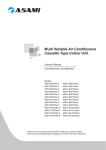
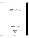
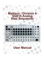
1 Table o’ Contents Welcome ......................................................................................................................... 3 Unpacking, Power Requirements, and Power Up Procedure ......................................... 4 SQ816 Panel Layout ....................................................................................................... 5 Definitions ....................................................................................................................... 6 Timing Section ................................................................................................................. 8 Stage Control Section ................................................................................................... 10 Stage Matrix ................................................................................................................. 11 Response Control Section ............................................................................................ 13 Output Section ............................................................................................................... 14 Interface Section ........................................................................................................... 16 User-Programmable Functions ..................................................................................... 17 Adjustments and Trim Procedures ............................................................................... 22 Ver 1.27 2013-02-01 2 Welcome Thank you for becoming the proud owner of one of the most exciting new products to come from the combined laboratories of Mattson Mini Modular and Division 6: The SQ816 Analog Step Sequencer. The SQ816 sequencer is a joint project between Mattson Mini Modular and Division 6 that has been in development for more than a year. And what a sequencer it has become! There are two formats - each is available from either the Division 6 or the Mattson Mini Modular web sites, or from select dealers. Division 6: http://division-6.com/shop/Synthesizers/ MMM: http://www.mattsonminimodular.com/shop/index.php?main_page=index&cPath=5_10 The Mattson Mini Modular format is comprised of two separate modules. The main SQ816 sequencer module is a 3-wide Mattson format module and the Expansion module is a 2-wide Mattson format module. The Division 6 SQ816 sequencer module combines both the Main SQ816 sequencer and Expansion modules into one 52HP (10-3/8” W) Eurorack format module. I have over 30 years of synthesizer history starting with the invention and production of the first actively portable self-contained synthesizer, which I named the Syntar in 1978. It was innovative for its time and was the first “keytar” produced. I use the term “Keytar” in its commonly utilized generic term. I’ve been playing with analog step sequencers for 30 plus years, and decided to produce a system that had all of the features I enjoyed, the features I always wished they had, and designed out the stuff I didn’t like. I also added a few extra things just because I could, and because I thought they were awesome features to try! The SQ816 is the result of that determination. I designed the hardware and incorporated the help of Division 6 to write and implement the software to create a truly amazing step sequencer. The SQ816 is designed to be primarily utilized as a CV/Gate controller. There are numerous inputs and outputs to help facilitate stand-alone operation with virtually any analog CV/Gate synthesizer system and expansion interfaces to allow the operation of multiple SQ816 sequencers in series or parallel. This manual has several parts. There is a Definitions section to help you understand the terminology utilized within the text of this manual, a Panel Layout section which explains the primary panel control and I/O functions, dedicated sections for each of the major function blocks on the SQ816, and a programming section which explains the multitude of user-programmable features. A Calibration section is also provided to allow you to tweak some of the functions to suit your preference or “dial in” some parameters to match outboard system responses. The calibrations detailed allow the user to change LED brightness, adjust the upper and lower ranges of the internal VC clock, and tweak in all of the 1Volt / Octave input and output functions. We will be developing short videos that highlight specific functions and show a few hints and tips. This will be an ongoing project and will be available for viewing on my YouTube channel. My user name on YouTube is MMModsynth, so check it often for new videos. Software updates via USB will be available on the SQ816 page on the Mattson Mini Modular WIKI site and on the Division 6 web site when they are available. Thank you again. We’ve had a lot of fun developing this product, and we’re looking forward to seeing the creativity from our customers utilizing this module. George Mattson 3 Unpacking, Power Requirements, and Power Up Sequence What’s in the box? When you open the packaging for your SQ816 sequencer, you’ll find: The SQ816 sequencer Programming Quick Reference card Jacklight Power cable USB cable Mounting screws (4) Power requirements: The Mattson/ Division 6 sequencer was designed to operate from either the standard Eurorack power standard of +/- 12VDC or the +/- 15VDC power found on many other synthesizer systems. The +V line draws 86mA, while the –V line draws 32mA. The SQ816 has a 10 pin dual row keyed power header and a 6 pin MTA header on the main board. Either connector can be used to power the system. The supplied power cable has a 10 pin keyed socket on one end of the ribbon cable and a 16 pin keyed socket on the other end. The 10 pin socket connects to the 10 pin keyed header on the lower-right of the SQ816 sequencer main board (when viewed from the rear). The “stripe” on the ribbon cable is oriented to be located toward the bottom of the circuit board. Since the supplied power cable is keyed, you can’t plug it in backward. If you use a different power cable that isn’t keyed and connect it backward, no problem - the SQ816 automatically orients the power to the proper polarity. Connect the keyed 16 pin socket on the other end of the ribbon cable to your system power bus. If your power distribution headers aren’t keyed, verify the stripe location prior to connecting. The stripe indicates the negative voltage (V-). The SQ816 sequencer clock is calibrated for the power scheme utilized based on the format provided. The only effect of using a higher or lower voltage power supply is that; the lower the power supply voltage, the faster the VC clock will cycle and it will need to have the range adjusted. Refer to the Adjustments and Trim Procedures section at the end of this manual for further information. Power up sequence: On initial power up, the SQ816 will initially perform an LED check by producing three scans across the Stage Status LEDs. On the first scan, the LEDs will light red. On the second scan, the LEDs will light yellow, and on the third scan the LEDs will light green. On each scan, the clock LED will be lit continuously at the current scan color. After the LED check, The LEDs will go dark and then display the software version number. The stage number of the LED will indicate the numeric value (1-8), and the clock LED is utilized to indicate the numeral 0 (zero). The first LED indicates the integer portion of the version number. The second LED indicates the first decimal number. The third LED indicates the second decimal number. The SQ816 sequencer will enter ready mode (no stages lit, clock LED flashing) after the Version Number display We’ve also created a short video to illustrate the power up routine: www.youtube.com/watch?v=jns2ajQR1JE 4 SQ816 Panel Layout 5 Definitions Ready or “Stand by”: Clock running, no stages active. Clock Indicator LED flashing red at clock rate (indicating Gate Mute) CV: Control Voltage. A voltage used to change an operational parameter. Usually between +/- 15VDC. VC: Voltage Controlled. A functional parameter that can be altered by applying a Control Voltage. 1V/Oct: One Volt per Octave. A “standard” where each volt applied will cause an operational change of one octave on pitch related devices. Gate: A voltage change used for initiating a specific event. Usually going from 0V to either +5V or +15V Stage Gate: A gate generated from the activation of a specific stage event. The SQ816 stage gates produce a +5V gate pulse. “Start” or “Beginning”: The beginning of a sequence. Stage 1 in Forward mode. Stage 8 in Reverse / 8 channel mode. Stage 16 in Reverse / 16 channel mode. Start Zone: A region in the lowest CCW position of the CV-A and/or CV-B controls. In pROGram mode, the active stage LED will flash when the region is active In Run mode, the sequence will progress to the stage prior to the stage set as “Start”, and then return to the beginning when the sequence is started. In Loop mode, the beginning is the first stage of a local sequence. In 1X mode, the beginning is assumed to be off system. The sequence will truncate, generate an XP out pulse and enter Ready Mode. Last stage: The last stage of a programmed sequence before repeating, changing direction, or going into Ready Mode. ROG: Run-On-Gate. A sub function of pROG mode where stage advances occur only when a gate is applied to the ROG input. PIG: Pause-Including-Gate. A Run mode operation where a gate applied to the ROG input will stop stage advances until the Gate is released. The main gate continues to be generated at the clock rate. SOS: Start-On-Stage. A start operation where starting the stage advancement will play the current stage first before advancing. SON: Start-On-Next. A start operation where starting the stage advancement will play the next stage first before advancing. Loop/1X: Control for determining if a sequence repeats, or makes one pass and enters Ready mode. Var: Variable. A control voltage generated by the Var settings. Primarily utilized to vary the clock rate on a per stage basis. XP: eXPansion. Used for off-module interfacing and timing. 6 Definitions (continued) Zoned Mute: Two regions in the upper CW position of the CV-A and CV-B controls for determining if the Main Gate or Main Gate and Stage Gate are suppressed for a specific stage. During a stage specific mute, the previous valid generated CV if held during the muted stage. X in: eXternal Input. Used for interfacing and summing external CVs to the function specific output. Local: Refers to on-system operations. Global: Pertaining to all stages, or a bank of stages during an operation. Usually selected by programming in Ready mode. Clock: Timing device for determining the stage advance rate. An external clock applied to the Ext Clk input interrupts and replaces the internal VC clock. The Tap Tempo feature interrupts and replaces the internal VC clock or the external clock. Quantize / Linear: Linear mode allows for a continuous sweep from 0-3 Volts using the control knob for a stage. No MIDI data is output for a bank in Linear mode. In Quantize mode, the full CV range is stepped in semitone values in the 12 semitone/octave western scale. MIDI note data output is enabled for a bank set to Quantize mode. Bus: Also called a bank. The output signal from a specific row of stage settings. 7 Timing Section The Timing Section sets stage advance timing and contains the LED Clock Indicator Master Clk: Rate control for internal clock. Using the Master Clock panel control, the minimum rate is about 10 seconds per stage and the maximum rate is about 100 Hz. Both limits can be affected by a control voltage applied to the Clk CV In jack and adjusted with the Clk CV Amt control. With a negative CV applied, the minimum rate is about 1.5 hours per stage. With a positive CV, the maximum rate tops out at about 133 Hz before the LEDs and gate start cutting out, but that can be fun too. LED Clock Indicator: The Clock Indicator LED flashes to indicate the frequency of the internal clock oscillator. The clock LED is also used to confirm that a user function has been programmed, and the LED color will indicate one of the following Green: Internal VC Clock or external clock at the Ext Clk In jack is in control of the stage advance timing. The LED flashes at stage advance clock rate. Yellow: Indicates user programmed Tap-Tempo control of the stage advance. VC internal and external clocks are disabled. Red: Indicates that the main gate output is disabled (muted) either from a stage setting or manually invoked. Clk CV Amt: Clock Control Voltage Amount. Adjusts the amount of modulation from the Clk CV In jack. Clk CV In: Control Voltage input for modulating the rate of the internal clock. See Master Clk for more details. CV Amt: Used for adjusting the amount of voltage change applied to the Bus A and Bus B outputs from the CV In jack (Fully CCW = no change, Fully CW is about 1V/Octave). CV In: Used for applying an external CV to both Bus A and Bus B outputs. This is an analog input, and will not affect MIDI out pitch. Ext Clk In: External Clock Input. 8 Timing Section (continued) ROG In: Run On Gate Input. See the User-Programmable Functions section for more detail on the ROG Input. Footswitch: An input jack for a normally-open shorting type footswitch. It performs the same function as the pushbutton. See the User-Programmable Functions section for more detail on using the Footswitch input. USB: See the Interface Section for more details. 9 Stage Control Section The Stage control section includes operational settings for programming, stopping and running the sequencer. Included are stage advance controls for setting forward, reverse, or ping pong operation. In addition, the duration of each stage can be set to be constant, or determined by the internal VC Clock under control of the VAR knob settings. Run/Stop-Reset/pROG switch: The main user control for starting, stopping, or programming the sequencer. The switch position is also used for selecting specific user program functions. Run: Normal operational for stage advance at the controlling clock rate. Stop-Reset: Halts stage advance operation. First button press resets to beginning stage. Subsequent button presses program Tap-Tempo rate. pROG: Stage pROGramming mode. Stage selection advances with each button press. The Gate is activated to assist with settings. The (ROG) position is also for program selection and utilizing ROG mode. Fwd/PP-Rnd/Rev switch: Main directional control The switch position is also used as a bank pointer during specific user program functions. Note: If the SON/SOS switch is in the SOS position, the sequence will double hit the beginning and endpoints of the sequence while in Ping-Pong mode. Fwd: Active stage advances in increasing stage numbers. PP-Rnd: Active stage advances from beginning to last stage and reverses direction. Rnd = Random stage number generation. Invoked by pressing the push button momentarily while running. Rev: Active stage advances in retrograde in decreasing stage numbers. Var/Equal switch: Allows for selecting equal tempered stage advance timing or variable stage length timing. Var: Var row stage setting controls the VC clock rate for a specific stage. Equal: Clock rate is equal tempered and not affected by the Var row stage settings. XP In: See Interface Section for more details. 10 Stage Matrix The Stage Matrix includes the controls for setting the values of each row for each stage and LEDs for indicating stage status. The stage controls are in a matrix of three rows and eight columns with a status LED above each column. Stage LED: Provides a visual indication of the stage status. In pROGram mode, the LED flashes if the stage CV control is in the start zone (CCW). It also flashes red for main gate mute and is solid red for main and stage gate mute selection.(CW) Off: Stage column is inactive. Green: Stages 1-8 are active, depending on which stage is lit. CV-A is applied to the CV-A output. Yellow: (in 16 channel mode) Stages 9-16 are active, CV-B setting is applied to the CV-A output. Red: The Main Gate and/or the Stage Gate is not generated for that stage. Effectively used for a stage mute. CV A row: Used for selecting stage CV output, start point or, main gate and stage gate mute. Row A is active during stage 1-8 operation. Fully CCW to slightly CW sets the Start Stage. The Status LED will flash at the clock rate Fully CW to slightly CCW sets the Mute Stage. The Status LED will be red. Flashing red (Zone 1) means that the Main Gate will not be generated for that stage, although the Stage Gate will still be active. Solid red (Zone 2) means that both the Main Gate and Stage Gate will not be generated for that stage. Between the Start and Mute Zones, the CV control provides a 0-3V (three octave) CV to the CV-A output. 11 Stage Matrix (continued) Var row: Used for selecting a CV output for the active stage. CV output range is approximately 0 to 3 Volts. The direct CV is available at the Var Out jack. If the Var/Equal switch is in the Var position, this CV setting is applied to the VC Clock timing. During 16 channel operations, this CV is routed to the CV-B output. CV B row: Used for selecting stage CV output, Start Point, or Main Gate and Stage Gate mutes. During 8 channel operation, this CV is applied to the CV-B output, and Zone Position controls for Row B are disabled. This acts as a 2 x 8 step sequence where Row CV-A controls the CV-A output, and Row B controls the CV-B output. During 16 channel operations, the CV-B row controls stages 9-16 and the CV output is routed to the CV-A output. Think of this as a 1 x 16 step sequence, with the CV for all 16 stages going to the CV-A output. The zone position controls for Row B are enabled and the Stage LED will light yellow to indicate the CV-B row is active. Stage Gates: Individual gate outputs for each stage. A +5V gate output mapped to specific active stage. The Stage Gate is active for a stage set to Zone 1 Mute. The Stage Gate is inactive for a stage set to Zone 2 Mute. The Gate length is set by the Main Gate Length program setting. Default = ”Follow.” See the UserProgrammable Functions section for more information. 12 Response Control Section The Response Control Section includes controls for setting operational parameters. 8/16 select switch: Sets the mode to 8 channel or 16 channel operation. Also used when toggled back and forth within one second to invoke user programs. Loop/1X select switch: Determines if the sequencer will advance to the end in one pass or loop continuously. Also used when toggled back and forth within one second to invoke user programs. (Consider Loop as being primarily for local operations and 1X for basic system interface with other systems.) …But, that’s just a general consideration… 1X mode: Sequencer will advance to the last stage and enter ready “stand by” mode until reset. In the 1X mode, an XP Out pulse is generated at the last stage +1 clock cycle. Loop mode: The sequence will restart to the beginning after the last stage is reached. No XP out pulse is generated in loop operations. SOS/SON select switch: Control for determining how the sequencer starts. Also used when toggled back and forth within one second to invoke user programs. SOS: Start-On-Stage. When the sequencer stage advance is invoked, the current stage is played before advancing. In Ping-Pong operation, the sequence will play the beginning and the end stage of the sequence twice. Think of the operation as playing all sequence stages then, starting over the other direction. SON: Start-On-Next (stage). Typical sequencer start. When the sequencer stage advance is invoked, the next stage is played first. XP Out jack: eXPansion out. See the Interface Section for more details. 13 Output Section The Output Section includes the outputs and controls for the CV channels, the Gate and Clock outputs, and interfacing. “Lots of Stuff” pushbutton: Primary user input switch based on current mode. In pROG mode, advances the stage once per button press, it generates one clock pulse per press. If held in pROG mode continuously for over three seconds, the stages will advance at the clock rate until released. In Stop mode, the first button press sets the active stage to the Start stage. Subsequent button presses in Stop mode will program Tap Tempo mode (average of last 5 button presses). If inadvertently stuck in Tap Tempo mode, hold pushbutton for ~5 seconds to exit. The Clock LED will switch from yellow to green or red if mute is active. Holding the button for more than 10 seconds will initiate a soft reboot. In Run mode, pressing the push button will mute the Main Gate output. The clock LED will be red. Pushbutton mutes will not hold the last valid stage value at the CV output. In PP-Rnd mode (Ping PongRandom), each button press toggles between Ping Pong and Random stage generation. When returning to Ping Pong from Random, the sequence will start on the stage and direction it was on when Random was invoked. When switching between Ping Pong and Random, holding the Pushbutton will invoke the gate mute after the mode change after one-half of a clock cycle. CV Offset: Analog control that applies 0 to approximately 1.1V (a little over an octave) for tuning both CV outputs. This control will not affect the MIDI note tuning. CV-A X In: An external VC input applied to the CV A output. Primarily used for multiple system interfacing. CV-A Out: The main CV output. Channels 1-8 in 8 channel mode. Channels 1-16 (CV A and CV B rows) in 16 channel mode. Clock Out: Direct clock output available for interfacing. In Run Mode, the clock output is available. In pROG Mode, the Clock Out jack outputs one clock pulse for every pushbutton press. 14 Output Section (continued) Gate Out: Main gate output typically applied to an Envelope Generator. Programmable for Short, Follow (clock cycle) and Long. See the Gate Length feature in the User-Programmable Functions section for more details. CV-B X In: An external VC input that is applied to the CV-B output. Primarily used for multiple system interfacing. CV-B Out: Secondary CV output. CV-B row available during 8 channel operation. Var row available during 16 channel operation. Var X In: An external VC input that is applied to the Var output. Primarily used for multiple system interfacing. Var Out: Raw CV output from the Var row knob settings. Gate X In: Used for daisy chaining external gates for multi-system operation. It is applied to the Gate out. MIDI Out: Two channel MIDI output providing note value, note on and note off MIDI data for each output bank. The MIDI output provides MIDI note values based on the active stage setting. The note values are not affected by any of the CV inputs (CV-A X In, CV-B X In, CV In, CV Amt, CV Offset, VAR X In). The MIDI values are generated based on the CV-A and CV-B output bus active in 8 or 16 channel mode. In 8 channel mode, the MIDI is generated based on the CV-A setting for one note and CV-B for the second note. In 16 channel mode, CV-A + CV-B from the CV-A bus generates the first MIDI note, The Var settings from the CV-B bus generates the second MIDI note. Note length is determined by the user main Gate Length program setting. Default = ”Follow”) The default MIDI channel is channel 1 for both CV-A and CV-B outputs. Each CV bus can be programmed to any MIDI channel 1-16 or, matched pairs. 1-9, 2-10, 3-11, etc. MIDI channels can be set to sequence through the MIDI channels where the MIDI channel = the active stage number. MIDI is only output if a bank is in Quantize mode. No MIDI note data for a specific bank is generated when that bank is in Linear mode. 15 Interface Section The Interface Section contains input and output jacks for external system interfacing. XP In: (eXPansion in). Used for start control interfacing between systems. A gate applied to this input will set the beginning stage immediately in both 1X and Loop operations. Detects leading edge so, applied gate length is not critical. Sets stage beginning in Run, pROG and Ready modes. (use a gate to send back to the beginning stage regardless of current stage position) XP Out: (eXPansion out). Generates a start pulse at the end of a sequence +1 clock pulse. (useful for starting another sequencer in time) If the SQ816 sequencer is in 1X mode, patching XP out to XP in essentially performs the same function as Placing the Loop/1X switch in the Loop position.. Footswitch: See “Footswitch” in the User Programmable Functions section. USB: USB input for updating the latest software version from a computer connected to the internet. Later software revisions may allow for utilizing this input for DAW timing control 16 User-Programmable Functions 17 User-Programmable Functions (continued) There are several parameters that can be changed by the user to enhance their operational preference on the SQ816 sequencer. The programmable parameters are selected by using combinations of the Stage Control switches, and activated/deactivated by toggling one of the three Response Control switches back and forth within 1 second. The Run/Stop/pROG switch position will select a set of three possible program functions. Toggling one of the three Response Control switches (8/16, Loop/1X or SOS/SON) back and forth will then select or deselect a specific program function. The Fwd/PP-Rnd/Rev switch is primarily used to select the specific bank or row to apply the selected program function. The Fwd position will typically select Bank A, the Rev position will select bank B, and the PP-Rnd position will select both the A and B banks. The status of the SQ816 sequencer will determine if the program operation will apply to a stage specific function or a global function. If the SQ816 is in Ready mode, the program will affect all of the selected banks. If the SQ816 is in Active mode (i.e. a stage is lit), the active stage number will specify which stage has a parameter programmed (e.g. a stage specific octave bump) or, is used to determine a specific number (e.g. MIDI channel selection). The settings of the user-programmable features are saved in memory during power off and are still active as programmed when the power is restored. To deactivate a programmable feature, repeat the specific program operation. To cancel all of the user program settings and restore the SQ816 sequencer to the factory defaults, turn off the SQ816 power, put ALL switches in the up position, then press and hold the “Lots of Stuff” Pushbutton while restoring power. ROG: Run On Gate: The SQ816 sequencer holds and waits on an active stage. No gates are generated and the SQ816 sequencer advances at the clock rate only when a gate (+5V or greater) is present at the ROG Input jack. The SQ816 stops when the gate at the ROG Input drops back down to 0V. Default = pROGram mode. (Hint: The sequence will start on the present stage or the next stage depending on the position of the SON/SOS switch). To activate, place the Run/Stop/pROG switch into the pROG position and toggle the Loop/1X switch back and forth within 1 second. The gate will drop out and the SQ816 sequencer will advance at the clock rate when a gate is applied to the ROG Input jack. To deactivate, move the Run/Stop/pROG switch to the Stop position. Tap-Tempo: Tap tempo allows the user to program the tempo of the stage advance, as well as the gate length between clock cycles based on tapping the “Lots of Stuff” push button. Default = Off. To activate, place the Run/Stop/pROG switch into the Stop position (the SQ816 sequencer can be in the Ready or Active mode), and tap the “Lots of Stuff” push button at the time interval desired. The gate length will be programmed to the length of time the push button is held between time intervals. The Clock LED will flash yellow at the Tap Tempo rate to indicate Tap Tempo timing control. In Tap Tempo mode, the internal VC clock and any Ext Clock inputs are suppressed and not active. The tempo rate and gate length are calculated by taking the average of the last five button presses. To deactivate, press and hold the “Lots of Stuff” push button for more than 5 seconds while in Stop mode until the clock LED changes from yellow (Tap Tempo control) to green (Active stage, VC clock, stage not 18 User-Programmable Functions (continued) muted) or red (Active stage is muted or the sequencer is in Ready mode). Note: While in Stop Mode, the first button press is used put the SQ816 in Active mode and set the active stage to the beginning. Subsequent Push Button presses will start the Tap Tempo programming procedure. To perform Tap Tempo programming without resetting the SQ816 to the beginning stage, apply a Gate to the ROG input while programming Tap Tempo. Gate length: The Gate length for each stage advance can be user programmed to one of three desired lengths: Short, Follow and Long. Default = Follow. The selection applies to both the main gate and stage gate outputs. In the Short setting, the gate length is essentially a trigger fixed at 10 milliseconds. In the Follow setting, the gate length follows the controlling clock waveform. In the Long setting, the gate length is calculated to be 40% longer than from the rising edge to the falling edge of the clock waveform. Essentially, 90% of the clock cycle if using a 50% duty cycle clock. If the clock duty cycle is greater than 50%? Fun times ensue… To activate, ensure that the SQ816 sequencer is in active mode on any stage and place the Run/Stop/pROG switch into the pROG position. Use the Fwd/PP-Rnd/Rev switch to select the desired Gate Length (“FWD” = Short, “PP-RND” = Follow, “REV” = Long), and then toggle the 8/16 switch back and forth within one second to program the selection. To deactivate, program another Gate Length selection. Verification: Ears, ears, ears… Octave (Global): Global Octave will offset the output of the selected bus output (CV-A Out or CV-B Out) up by one Volt. This will raise the pitch of a specified output bank up one octave. Selecting the octave offset again will remove the offset. Default = No offset. To activate, place the SQ816 in Ready mode (no stages active). Set the Run/Stop-Reset/pROG switch into the down (pROG) position. Use the Fwd/PP-Rnd/Rev switch to select the desired bank to change (“FWD” = A, “PP-RND” = both A and B, “REV” = B), and then toggle the SOS/SON switch back and forth within one second to program the selection. To deactivate, repeat the procedure. The offset status toggles from On to Off with each repeat of the procedure. Note: The PP-Rnd selection will toggle the octave selection for both banks. If one bank is set to On and the second bank is set to Off, invoking the Octave offset will toggle both banks. The Global offsets are mapped to the specified bank output. If the CV-B bank is set for global octave 0 and the CV-A bank is set for global octave +1, when switching to 16 stage mode, the CV-B stage settings will be raised an octave during the playback of stages 9-16. Verification: When invoked, the clock LED will light for 1 second if a single bank octave offset is selected. The clock LED will light yellow for 1 second if the global offset was set to +1 octave. The clock LED will light green for 1 second if the global offset was set back to 0 octave (no octave offset). The clock LED will light yellow for 1 second, green for 1 second and yellow for 1 second indicating a bank swap or two bank operation. Octave (Stage): Individual stages can be bumped up an octave or, set back to 0 octave independent of the Global bank octave setting. Default: No offset. To understand how stage octave programming functions, consider the CV-A and CV-B outputs in 8 channel mode as 8A and 8B. The stages 8-16 and the Var row during 16 channel operation can be considered as 19 User-Programmable Functions (continued) 16A being generated from the CV-A Out jack and Var B being generated from the CV-B out jack. Note: The programmed octave shift stays with the bank and/or stage programmed. When switching from 8 channel to 16 channel operation, the stage 1-8 programmed octaves remain as programmed. The 8 channel B setting is not the same as the 16 channel setting when CV-B shifts to the CV-A out bus, i.e. if stage 3B is programmed up an octave and the SQ816 is switched from 8 to 16 channel mode, Stage 11 will not be changed by the octave operation and will need to be set separately. To activate, set the SQ816 to Active mode and set it to the stage desired for octave programming. Set the Run/Stop-Reset/pROG switch into the down (pROG) position, and use the Fwd/PP-Rnd/Rev switch to select the desired stage to change: The Fwd position selects the CV-A selected stage. (8 ch: Stage 1-8A. 16 ch: Stage 1-16A) The Rev position selects the CV-B selected stage. (8 ch: Stage 1-8B. 16 ch: Stage Var 1-8) The PP-Rnd position selects both active stages in a column based on the 8/16 channel selection. Toggle the SOS/SON switch back and forth within 1 second to program the selection. To deactivate, repeat the procedure. The offset status toggles back and forth between On and Off with each repeat. Verification: When invoked, the set stage LED will light for 1 second if a single stage is selected. The Stage LED will light yellow for 1 second if the stage offset was set to +1 octave. The Stage LED will light green for 1 second if the stage offset was set to 0 octave (no offset). The stage LED will light yellow for 1 second, green for 1 second and yellow for 1 second indicating a stage swap or two stage operation. Quantize: The CV-A and CV-B outputs on the SQ816 sequencer are linear voltages. Adjusting the active stage control will sweep continuously from 0V to 3V, producing a three octave range based on the “standard” 1V/Octave output scheme. To assist in setting the outputs to drive oscillators in discreet semitone steps, the CV-A and CV-B banks of the SQ816 sequencer can be programmed to quantize the outputs. Default = Linear mode (not quantized). Note: When a bank quantize is enabled, it enables the MIDI output for that bank - sort of a MIDI on/off. To activate, place the Run/Stop/pROG switch into the Stop position. The program setup can be performed in either Ready or Active modes. Use the Fwd/PP-Rnd/Rev switch to select the desired bank to change (“Fwd” = A, “PP-Rnd” = A and B, “Rev” = B), and then toggle the 8/16 switch back and forth within 1 second to program the selection. To deactivate, repeat the procedure. The quantize status toggles back and forth between On and Off with each repeat. Verification: When invoked, the clock LED will light in a three-color sequence within 1 second to indicate that the quantize program parameter has been changed: Red/Yellow/Green: The selected bank was set from Quantize to Linear. Green/Yellow/Red: The selected bank was set from Linear to Quantize. Red/Green/Red: Indicates that a dual bank Quantize/Linear or swap operation was performed. MIDI Channel: When an output bank is programmed for quantized operation, it enables the MIDI output for that bank. Default = Both banks set to MIDI channel 1. Each bank can be assigned an independent MIDI channel, or the SQ816 can advance through all sixteen MIDI channels, producing a MIDI channel output based on the active stage number. That was thrown in for fun… 20 User-Programmable Functions (continued) To activate, step the SQ816 to the stage number that is equal to the desired MIDI channel. Place the Run/Stop/pROG switch into the Stop position. Use the Fwd/PP-Rnd/Rev switch to select the desired bank to change (“Fwd” = A, “PP-Rnd” = A and B, “Rev” = B), and then toggle the SOS/SON switch back and forth within 1 second to program the MIDI Channel. MIDI Channel sequencing: To activate MIDI channel sequencing, place the SQ816 sequencer into Ready mode (no stages active). Toggle the SOS/SON switch back and forth within 1 second to program the MIDI Channel sequence. If the Fwd/PP-Rnd/Rev switch is in the Fwd or Rev positions when MIDI Channel sequencing is invoked, the MIDI channel output will match the stage number when in run mode. If the Fwd/PP-Rnd/Rev switch is in the PP-Rnd position AND the 8Ch/16Ch switch is in the 8 Ch position when MIDI is invoked, the MIDI channel output will sequence in matched column pairs (i.e. 1/9, 2/10, 3/11….8/16). When this program is invoked and in Run mode, switching live between 8 Ch and 16 Ch modes will switch between the 8 Channel matched pairs to 16 Ch dual-note mode where the MIDI Channel matches the stage number. To deactivate: Repeat the procedure, programming a different channel number if desired. Verification: When invoked, the active Stage LED will flash green three times quickly to indicate that the MIDI channel has been programmed for the selected bank. For MIDI channel sequencing, The Stage LEDs will light green and scan from Stage 1 to Stage 8 Notes: The MIDI Note Off command follows the Gate Length setting. If a stage is set to Stage Mute, no MIDI data is generated for that stage. Run mute operations will suppress MIDI note generation while the Run Mute is active. Run Mute: During run operations, the main gate output can be muted by pressing and holding the “Lots of Stuff” pushbutton. This disables the main gate output only and not the stage gate outputs. This allows for any stage related events to continue during a mute operation. Note: Any pushbutton operation can be performed with an appropriate footswitch installed. Foot switch: The footswitch input allows for inserting a normally open, shorting style foot switch into the jack and creating foot control of the SQ816 sequencer. When connected, the footswitch performs the same operations as the “Lots of Stuff” push button. Caution: Most foot switches manufactured utilize a heavy cable and terminate with a 1/4” phono plug. The Eurorack and Stand alone version of the SQ816 provides two parallel inputs (1/4” and 3.5mm jacks) for the footswitch. These can also be used to “multi” or pass the footswitch closure out to other systems. The Mattson style SQ816 Sequencer provides the footswitch interface on the SQ816 Expansion module and is a 3.5mm jack only. A 1/4” to 3.5mm adapter must be used to insert a 1/4” footswitch phono plug. If this method is used, care must be taken to relieve the strain of the cable applied to the jack. Otherwise, the jack could be damaged. If the footswitch you wish to use is a normally-closed (N/C) style footswitch that opens the switch when active, no problem (read on to the next item): 21 User-Programmable Functions (continued) Alt Footswitch jumper: Located to the right of the R126T (CVB) trim on the bottom-left section of the main board is a 3-pin header labeled “FS” with a shorting jumper installed on the left and center pins (Norm) position. The SQ816 will process a normally-open (N/O) footswitch that parallels the “Lots of Stuff” pushbutton function while the jumper is in the “Norm” position. If the jumper is installed on the center and right pins (Alt position), the SQ816 Sequencer will accept a N/C footswitch. Actually, in this mode, the SQ816 will determine which type of footswitch is connected to the Footswitch input jack and configure its operation accordingly. This is the current, original stock Alt Footswitch function. Future software revisions may change the Alt Footswitch function to perform a different operation. Gate Controlled Mute: Yes, there is one. It’s secret and hidden. Once you’re familiar with the SQ816 sequencer, write and ask about this feature… In the meantime, go have fun!!! 22 cRD cGN CN5 VR1 U8 U3 U4 sRD sGN + G _ CN4 CN2 U9 U2 bRATE B-X R126T CVA R129T R125T R128T R124T S/N: A-X CVB VR2 U6 R122T U7 DAC R120T R127T C8 R123T CN3 R121T Adjustments and Trim Procedures +RATE R130T + _ G Footswitch Jumper Norm FS AF MIDI out MIDI in 1: Clock LED Red brightness Power up. In Ready mode, using the internal VC clock (not Tap-Tempo) the clock LED flashes red, indicating a main gate mute. Adjust R121T (cRD) to brighten or dim the clock LED. 2(a): Clock LED Green brightness Set the 8Ch/16Ch switch up to the 8ch position. From step one, Place the Run>Stop>pROG switch into the center (Stop) position and press the push button to set the active first stage. Place the active stage CV control somewhere in the middle. The Clock LED should be flashing green. Adjust R120T (cGN) to brighten or dim the the clock LED. 2(b): Clock LED Yellow balance Press the push button rapidly 5 or 6 times to invoke Tap-Tempo mode. The clock LED should be flashing yellow at the tapped rate. The yellow color is determined by the balance of the red and green LEDs combined. Re-adjust R121T (cRD) and R120T (cGN) until the combination is yellow or, suitable to your preference. Hold the push button for 5 or 6 seconds until the clock LED flashes green at the internal clock rate, indicating the exit from Tap-Tempo mode. 3: Stage LED Green brightness A stage should be active and the Stage LED should be solid green. Adjust R121T (sGN) to brighten or dim the active stage green LED. 4(a): Stage LED Red brightness Adjust the active stage CV-A control fully clockwise. The Stage LED should be steady red indicating a Zone 2 mute. Adjust R122T (sRD) to brighten or dim the active stage red LED. 4(b): Stage LED Yellow brightness Place the Run>Stop>pROG switch into the down (pROG) position. Place the 8Ch/16Ch switch into the down (16Ch) position. Place the Loop/1X switch into the up (Loop) position. Press the push button repeatedly until the active stage cycles and shows yellow, indicating stages 9-16 are active. Adjust R121T (sGN) and R122T (sRD) until the combination is yellow or suitable to your preference. 23 Adjustments and Trim Procedures (continued) 5 and 6: VC Clock limits Before adjusting the VC Clock Limits (Trims 5 and 6), perform this setup first: Verify that the VC clock is active (not in Tap-Tempo mode). Remove any input from the Ext Clk In jack. Remove any input from the Clk CV In jack. Place the Var/Equal switch in the down (Equal) position. Rotate the Master Clk control fully CW Switch the Loop/1X switch into the up (Loop) position. Place the Run/Stop-Reset/pROG switch in the up (Run) position. Place the Master Clk rate control fully CW. Verify that all sequenced stages are in the Active region (no Zone positions). 5: VC Clock upper limit Adjust R130T (tRATE) until stage LEDs start to cut out. Then, back off slightly until all stage LEDs are lit equally. 6: VC Clock lower limit Rotate the Master Clk control fully CCW. Adjust R124T (bRATE) until the clock LED cycles about once every ten seconds. You may have to check and readjust both the upper and lower limits to verify. Volt/ Octave calibration The SQ816 is calibrated at the factory to respond to and generate 1Volt/Octave (1V/O) control voltages. We have found that in the field, many 1V/O generation devices either have gone out of calibration and 1V/O dependent devices have either drifted the other direction or have been adjusted to compensate. They work well together, but may not be as compatible when the SQ816 is inserted into the chain. We have provided this calibration information if you have the need to perform fine adjustments to make it perform accurately with your system. Steps 7 and 9 compensate the final CV output amplifiers on each bus for the inherent inconsistencies of the CV Amount control. Potentiometers don’t necessarily have a perfect 0 Ohm connection to the ends of the resistive element when they’re fully rotated to the stops, and there is usually a small amount of resistance. There are also tolerance variations in the resistors and circuitry used for the output amplifiers. Steps 7 and 9 allow for compensating the CV-A and CV-B bus outputs to create an output CV equal to the input CV when the CV Amount control is fully CW. That allows for using a 1V/O CV control for transposing the sequencer busses accurately if desired. Before adjusting the Volt/Octave calibration (Trims 7 through 11), perform this setup first: Rotate CV Offset control fully CCW. Set to Stage 1. Patch a 1V/Oct CV into the CV In jack. Press the lowest ‘C’ key or reference. Rotate the CV Amt control fully CW. Rotate the Stage 1 CV-A control fully CCW until the Stage LED flashes. Then rotate CW until the Stage LED stays constantly lit. Connect the CV-A Out jack to the 1V/Oct input of a VCO. Tune the VCO to a low ‘C.’ Use a reference tuned to unison with the VCO connected to the CV-A output, or use a tuner monitoring the VCO. Press a key or increase your 1V/O source to ‘C’ up three (or 4, 5 or 6) octaves. 7: CV-A Bus Adjust Adjust R125T (CVA) until the VCO is tuned to ‘C’ three (or 4, 5 or 6) octaves above the reference VCO. The point is to adjust it to match to however the VCO would respond if the controlling CV was connected directly to the VCO. 24 Adjustments and Trim Procedures (continued) 8: CV-A X In Adjust The CV-A X In input is just an external signal input to the CV-A output final amplifier. Sort of a buffered “through.” Once the output amplifier is adjusted properly, we want to ensure that whatever is patched into the CV-A X In jack is faithfully reproduced at the CV-A out jack. It adds to any voltage already present at the CV-A output. This is used for multiple system expansion but, it can also be used as a single bus transpose or modulation input. To calibrate, perform the following steps: Remove the 1V/O CV from the CV In input jack and patch it into the CVA-X In jack. Press the lowest ‘C’ key on your keyboard. Adjust your VCO to a ‘C’. Press a key or increase your 1V/O source to ‘C’ up three (or 4, 5 or 6) octaves. Adjust R128T (A-X) until the VCO is tuned to ‘C’ three (or 4, 5 or 6) octaves above the reference VCO. 9: CV-B Bus Adjust Now, we’ll repeat the procedures for the CV-B bus: Return the keyboard or reference CV back to the lowest ‘C.’ Remove the patch cord from the CV-A Out jack and connect it to the CV-B Out jack. Remove the patch cord from the CV-A X In jack and return it to the CV In jack. Make sure the CV Amt control is fully CW. Switch the 8 Ch/16 Ch switch to the up (8 Ch) position if it isn’t already in that position. Make sure the active stage is Stage 1. Adjust the Stage 1 CV-B (bottom row) control fully CCW. Tune the VCO to a low ‘C’ Tune the reference to be in unison with the VCO. Press a key or increase your 1V/O source to ‘C’ up three (or 4, 5 or 6) octaves Adjust R126T (CV-B) until the VCO is tuned to ‘C’ three (or 4, 5 or 6) octaves above the reference VCO. Essentially, it’s the same procedure as step 7, but this step adjusts the CV-B output. 10: CV-B X In Adjust This is the same procedure as step 8. Only it calibrates the CV-B external input. Remove the 1V/O CV from the CV In jack and patch it into the CV-B X In jack. Press the lowest ‘C’ key on your keyboard. Adjust your VCO to a ‘C’. Press a key or increase your 1V/O source to ‘C’ up three (or 4, 5 or 6) octaves. Adjust R129T (B-X) until the VCO is tuned to ‘C’ three (or 4, 5 or 6) octaves above the reference VCO. Basically, the CV In input should affect both the CV-A and CV-B output busses equally when the CV Amt control is fully clockwise. If the CV In voltage was plugged directly into the VCO, the VCO should respond the same. The CV-(A or B) X In inputs do the same, only there’s no amount control and they only affect one bus output each. The final calibration procedure is to adjust the range of the stage CV controls. The previous calibrations were to make sure the output amplifiers were adjusted to faithfully reproduce the signals applied to the CV inputs. The internal computer doesn’t monitor those inputs. The functions are entirely analog. The computer does monitor the Stage CV control settings. It determines the value of the control and responds to certain values on the high and low ends for Mute and Start functions. The active range between the endpoints is digitally converted and mapped to a 0-3V analog range through a Digital to Analog Converter or DAC. 25 Adjustments and Trim Procedures (continued) 11: DAC CV Bus Adjust We want to adjust the DAC reference to ensure that the full output range generated by the computer is 3V. This gives us a three octave range when the CV bus outputs are patched to a 1V/O responsive device. Using the same setup as before, remove any inputs from the CV In input jack. Remove the patch cord from the CV-B Out jack and insert it into the CV-A Out jack. Ensure that the SQ816 sequencer is active on Stage 1. Rotate the Stage 1 CV-A control (top row, far left stage control) fully CCW. The Stage 1 LED should be flashing green. Rotate the Stage 1 CV-A control slightly CW until the just when the Stage 1 LED stops flashing. Don’t go past that point. Adjust the VCO connected to the CV-A Out jack to a Low ‘C’. Rotate the CV-A Stage 1 control fully CW until the Stage 1 LED starts flashing red. Rotate the CV-A Stage 1 control slightly CCW until the Stage 1 LED stops flashing red and turns solid green. This is the full active range of the stage CV control and we want to adjust the computer output to be 3V. Adjust R127T (DAC) until the VCO is tuned to ‘C’ three octaves above the reference VCO. Double check by rotating the CV control from the low end of the active range to the high end of the active range. Although we have specified using a low ‘C’ as a reference, it doesn’t really matter what pitch you choose. As long as the ranges match from the lowest to the highest. We’ve adjusted the DAC for a 3V or, 3 octave range when controlling 1V/O devices. However, you could stretch or compress those values for experimental purposes or to compensate for devices requiring a different V/O “standard”. Be advised that the MIDI note output range may not match any experimental tunings. A helpful hint: Using MIDI devices as a tuning reference: The MIDI output can be used during calibration as an excellent calibration reference. The MIDI note values are calculated between the start and mute zones to always provide MIDI output notes ‘C’ to ‘C’ +3 octaves. These are unaffected by the analog calibration adjustments. Place the SQ816 Sequencer in Quantize mode to enable the MIDI output. Connect the MIDI output to a suitable MIDI-capable Sound generating device (verify channels match). Find a patch on the sound generating device that is constant with no effects or modulation such as a flute or cello setting. When the SQ816 Sequencer is in pROG mode, it will remain on the current stage setting and generate MIDI notes at the clock rate. The V/O and DAC calibrations can be made using the MIDI device as a pitch reference You’re all done now. Go play! 26