1
Allen-Bradley
Open-loop
Velocity
Control Module
(Cat. No. 1746-QV)
User
Manual
Important User Information
Because of the variety of uses for the products described in this
publication, those responsible for the application and use of this control
equipment must satisfy themselves that all necessary steps have been
taken to assure that each application and use meets all performance and
safety requirements, including any applicable laws, regulations, codes
and standards.
The illustrations, charts, sample programs and layout examples shown in
this guide are intended solely for purposes of example. Since there are
many variables and requirements associated with any particular
installation, Allen-Bradley does not assume responsibility or liability (to
include intellectual property liability) for actual use based upon the
examples shown in this publication.
Allen-Bradley publication SGI-1.1, Safety Guidelines for the
Application, Installation, and Maintenance of Solid-State Control
(available from your local Allen-Bradley office), describes some
important differences between solid-state equipment and
electromechanical devices that should be taken into consideration when
applying products such as those described in this publication.
Reproduction of the contents of this copyrighted publication, in whole or
in part, without written permission of Allen-Bradley Company, Inc., is
prohibited.
Throughout this manual we use notes to make you aware of safety
considerations:
!
ATTENTION: Identifies information about practices or
circumstances that can lead to personal injury or death,
property damage or economic loss.
Attention statements help you to:
• identify a hazard
• avoid the hazard
• recognize the consequences
Important:
Identifies information that is critical for successful
application and understanding of the product.
SLC is a trademark of Allen-Bradley Company, Inc. PKZIP and PKUNZIP are registered trademarks of PKWARE Inc.
Manual Changes
(Series A/D)
Changes to this revision of the manual include these additions:
• Considerations for Selecting the "15V dc Power Supply (chapter 4)
• Other Design Considerations (chapter 4)
• Testing for Proper System Operation (chapter 5)
• Power Supply Loading Specifications (appendix A)
Publication 1746-6.18 – April 1998
toc–ii
Summary of Changes
Notes:
Publication 1746-6.18 – April 1998
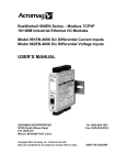
Table of Contents
System Overview . . . . . . . . . . . . . . . . . . . . . . . . . . . . . . . .
1–1
Chapter Objectives . . . . . . . . . . . . . . . . . . . . . . . . . . . . . . . . . .
What Is the 1746-QV Module? . . . . . . . . . . . . . . . . . . . . . . . . . .
What Is an SLC-500 System? . . . . . . . . . . . . . . . . . . . . . . . . . .
Why Use This System? . . . . . . . . . . . . . . . . . . . . . . . . . . . . . . .
How Does It Work? . . . . . . . . . . . . . . . . . . . . . . . . . . . . . . . . . .
What Are Typical Applications? . . . . . . . . . . . . . . . . . . . . . . . . . .
1–1
1–1
1–1
1–2
1–2
1–2
Quick Start . . . . . . . . . . . . . . . . . . . . . . . . . . . . . . . . . . . . .
2–1
Procedure . . . . . . . . . . . . . . . . . . . . . . . . . . . . . . . . . . . . . . . . .
2–1
Setting Up the Software . . . . . . . . . . . . . . . . . . . . . . . . . . .
3–1
Chapter Objectives . . . . . . . . . . . . . . . . . . . . . . . . . . . . . . . . . .
Obtaining the Ladder Program Electronically from
BBS or the Internet . . . . . . . . . . . . . . . . . . . . . . . . . . . . . . . .
About the Rockwell Bulletin Board System (BBS) . . . . . . . . . . . .
To Access BBS: . . . . . . . . . . . . . . . . . . . . . . . . . . . . . . . . . . . .
To Access the Internet: . . . . . . . . . . . . . . . . . . . . . . . . . . . . . . .
Configuring Your SLC Processor, Off-line . . . . . . . . . . . . . . . . . .
Modify N Files in Your SLC Processor, Off-line . . . . . . . . . . . . . .
Output Image Table with Profile Data . . . . . . . . . . . . . . . . . . . . .
General Conventions for Profiles . . . . . . . . . . . . . . . . . . . . . . . .
Profile Operation . . . . . . . . . . . . . . . . . . . . . . . . . . . . . . . . . . . .
3–1
Setting Up the Hardware . . . . . . . . . . . . . . . . . . . . . . . . . .
4–1
Chapter Objectives . . . . . . . . . . . . . . . . . . . . . . . . . . . . . . . . . .
Connect the LDT to Module Inputs . . . . . . . . . . . . . . . . . . . . . . .
Connect Module Outputs to Output Devices . . . . . . . . . . . . . . . . .
Minimizing Interference from Radiated Electrical Noise . . . . . . . . .
Considerations for the "15V dc Supply . . . . . . . . . . . . . . . . . . .
Selection of the "15V dc Power Supply . . . . . . . . . . . . . . . . . .
Application of the "15V dc Power Supply . . . . . . . . . . . . . . . . .
Other Design Considerations . . . . . . . . . . . . . . . . . . . . . . . . . . .
4–1
4–1
4–2
4–2
4–3
4–3
4–4
4–4
3–1
3–1
3–1
3–2
3–2
3–4
3–4
3–5
3–5
ii
Table of Contents
Operating the Module for the First Time . . . . . . . . . . . . . . .
5–1
Chapter Objectives . . . . . . . . . . . . . . . . . . . . . . . . . . . . . . . . . .
Power Up the System . . . . . . . . . . . . . . . . . . . . . . . . . . . . . . . .
Check Wiring and Grounding . . . . . . . . . . . . . . . . . . . . . . . . . .
Get Ready to Move the Ram . . . . . . . . . . . . . . . . . . . . . . . . . . .
Move the Ram . . . . . . . . . . . . . . . . . . . . . . . . . . . . . . . . . . . . .
Jog the Ram to the Reference Position . . . . . . . . . . . . . . . . . . .
Test for Proper System Operation . . . . . . . . . . . . . . . . . . . . . . . .
Troubleshoot Possible Problems . . . . . . . . . . . . . . . . . . . . . . . . .
Using Status Bits for Errors Detected by the Module . . . . . . . . . .
Troubleshooting Table . . . . . . . . . . . . . . . . . . . . . . . . . . . . . . .
Conditions That Control Module Outputs . . . . . . . . . . . . . . . . . .
5–1
5–1
5–1
5–2
5–2
5–3
5–4
5–4
5–4
5–5
5–5
Module Specifications . . . . . . . . . . . . . . . . . . . . . . . . . . . .
A–1
Electrical Specifications . . . . . . . . . . . . . . . . . . . . . . . . . . . . . . .
Physical Specifications . . . . . . . . . . . . . . . . . . . . . . . . . . . . . . .
Environmental Specifications . . . . . . . . . . . . . . . . . . . . . . . . . . .
A–1
A–1
A–1
Ladder Program . . . . . . . . . . . . . . . . . . . . . . . . . . . . . . . . .
B–1
SLC Processor Files . . . . . . . . . . . . . . . . . . . . . . . . . . . . .
C–1
Input Image Table . . . . . . . . . . . . . . . . . . . . . . . . . . . . . . . . . . .
G File . . . . . . . . . . . . . . . . . . . . . . . . . . . . . . . . . . . . . . . . . . . .
Output Image Table . . . . . . . . . . . . . . . . . . . . . . . . . . . . . . . . . .
C–1
C–2
C–2
Chapter Objectives
This chapter presents a conceptual overview of how you use the
1746-QV module in an application.
What Is the
1746-QV Module?
The 1746-QV module is part of an SLC-based open-loop control
system for controlling the speed and placement of an hydraulic ram.
The module accepts an input from a linear displacement transducer
(LDT) and motion profiles that you program into the SLC processor,
and varies its output in the range of "10V dc. The SLC processor
sends to the module a pair of extend and retract profiles that define
when to accelerate or decelerate hydraulic motion.
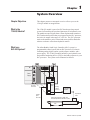
What Is an
SLC-500 System?
The Allen-Bradley Small Logic Controller (SLC) system is a
programmable control system with an SLC processor, I/O chassis
containing analog, digital, and/or special-purpose modules, and a
power supply. The 1746-QV module interfaces your hydraulic ram
and position-monitoring device (LDT) to the ladder sequence in your
SLC processor. The system can be illustrated as follows:
Power
Supply
HYDRAULIC
RUN
FAULT
LDT/"10V DC
SLC-500
Processor
Position
Input
from LDT
1746-QV
module
Analog
Output
"10v dc
Proportional
Amplifier
Proportional
Valve
Piston-type Hydraulic Cylinder and
Linear Displacement Transducer (LDT)
Axis
Motion
Publication 1746-6.18 April 1998
1–2
System Overview
Why Use This System?
Because you can change the speed of the hydraulic ram with extend
and retract profiles and store additional profiles (recipes) in data
table iNteger (N) files, this control system has these benefits:
• reduced cycle time – you can increase ram speed for faster operation
• reduced or eliminated pressure spikes and water-hammering for
smoother operation and less wear and tear on the machine –
you can profile accelerations and decelerations of the hydraulic ram
• energy savings – you can match the speed of the hydraulic pump
to the force that you need
• faster new-part change-over – you can store your setups and
minimize mechanical re-adjustments between parts
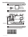
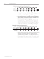
How Does It Work?
The 1746-QV module executes the extend and retract profiles that you
load to control the motion of the hydraulic ram. You can program up
to seven different voltages over the length of travel in both the extend
and retract directions to control how the ram accelerates or decelerates.
Voltage
3
Retract Direction
Voltage
Extend Direction
4
5
4
3
5
6
6
2
2
1
7
Segments
1
7
Segments
LDT Head
Position
LDT Head
Position
Each position setpoint triggers a corresponding voltage output in the
range of –10V to +10V dc that translates into speed. The LDT
provides high-speed position updates to the module for consistent and
repeatable motion.
What Are Typical
Applications?
Use the 1746-QV module in an SLC-based system for low-cost
control of:
•
•
•
•
•
hydraulic machinery
simple (non-CNC) hydraulic presses
diecasting machinery
welder placement
pneumatic actuators for clamping or placement
In addition, the module is designed to support standard proportional
amplifiers and retrofit into most existing hydraulic systems.
Publication 1746-6.18 April 1998
Use this chapter as an abbreviated procedure for getting the 1746-QV
module into operation or as an overview if you need more information.
Procedure
1.
Load Ladder Logic into Your Computer
Chapter 3
Obtain the ladder program (appendix B) from Rockwell Software Bulletin Board (BBS) or the Internet.
From BBS: (216) 646-ROCK (-7625). If a new user, follow prompts to register. Log in. Look for 1746QV
in the Allen-Bradley Products Library. The manual is in Word format. Download it into a hard drive subdirectory and decompress it with PKUNZIP available on BBS. The ladder program, VELMOD, is SLC500
code (65 Kbyte). Download it into a hard drive subdirectory where your programming software looks for files.
From Internet: webpage http://www.ab.com If a new user, click Join Now and follow prompts to
register. Log in. Search for QV: on homepage, click Search Our Site, insert QV in window, and click
search button. The manual is PDF format and requires Adobe Acrobat viewer. The ladder program is PDF
format and must be entered manually.
2.
Set Up Your Software
Chapter 3
Configure the SLC Processor and I/O with your programming software. Enter the following:
a) processor type, b) module I/O-chassis slot, c) module ID (13115), d) G-file size (7 words), and
e) G-file configuration values from the ladder program (appendix B).
Modify N files for the profile found in the ladder program (appendix B) to suite your application.
3.
Connect the LDT to the Module’s Input Terminal Block
Chapter 4
The following are connections between the 1746-QV module and typical LDTs such as
Temposonics, Balluff, Santest, and Gemco.
1746-QV Module
Input Terminal Block
8
7
6
5
4
3
2
1
Temposonics II,
RPM or DPM
(+) Gate Out
PS
(–) Gate Out
Common
Inter(–) Interrogate rogate
1
(+) Interrogate
(+)
(+) (–)
Frame
Shield/Frame
9 7 5 3 2
GND
–15V dc PS
10 8 6 4
PS Common
(–) (+)
(–)
+15v dc PS
Gate Out
"15V dc PS
Balluff
BTL-2-L2 & -2-M2
Interro- Gate Out (–)
Gate Out (+)
gate (–)
2
5
4
(–)
8
3
1
7 (+)
"15V
dc PS
Santest
GYRP & GYRG
NC
+15V
dc PS
2
1
PS
Common
3
4 (+)
5
7
6 (–)
Gate
Gate
Out (+)
Out (–)
Interrogate
6
Interrogate (+)
PS
Common
Gemco Quick-Stick II
951VP w/PWM Output
B–BLK PS Common
C–RED +15V dc PS
K–GRY + Interrogate
E–BRN –Sq Wave Out*
F–BLU +Sq Wave Out*
A–WHT –Interrogate
G, D, H RS232RXD
J–PUR 2nd PS COM
*951RS has pulse trigger
The views are looking at the connector on the LDT head.
1746-QV
Input Pin #
Function
Temposonics II
RPM or DPM
8
(+) Gate Out
4 – Pink
7
(–) Gate Out
3 – Gray
6
(–) Interrogate
10 – Green
5
(+) Interrogate
9 – Yellow
4
Shield/Frame
n/a
3
–15V dc PS
6 – Blue
2
PS Common
1 – White
1
+15V dc PS
5 – Red
Balluff
BTL-2-L2 & -M2
2 – Gray (note 1)
5 – Green (note 1)
3 – Pink
1 – Yellow
n/a
8 – White
6 – Blue
7 – Brown
Santest
GYRP/GYRG
Gemco QuickStick 951VP/RS
pin 5
F – Blue (note 1)
pin 7
E – Brown (note 1)
pin 6
A – White
pin 4
K – Gray
n/a
n/a
n/a
n/a
pin 3
B – Black
pin 1
C – Red
(+) and (–) wires of same function should be a twisted pair within the cable.
Note 1: In the table, we use the term “gate out” for pulse trigger or square wave (Gemco) and start/stop (Balluff -M2) LDT signals.
Publication 1746-6.18 April 1998
2–2
Quick Start
4.
Connect Module Output Terminals to Output Devices With Correct Bonding
Important: Connect the shield of the amplifier
output cable to a 0V connection in the amplifier.
+24V dc PS
0V dc PS
Servo Amplifier
(Proportional)
0V
1746-QV Output
Terminal Block
5.
Analog Output
("10v dc)
2
1
(+) Diff.
(–) Input
Chapter 4
Do NOT connect output
shields to earth ground
Outputs A
to valves B
To solenoid A
To solenoid B
Minimize Interference from Electrical Noise with Correct Shielding and Grounding
Chapter 4
Important: Connect PS output commons togerther.
Connect the following to earth ground: a) cable shields (except for amplifier outputs) at one end only,
b) input terminal 4, c) case grounds of PS and amplifier, e) LDT flange.
Case
GND
"15V PS
1746-QV
Module
24V PS
(–) (+)
(+) (C) (–)
Case
GND
Input
LDT
Power
1
2
3
LDT
Signals
5-8
Important: For correct bonding,
connect PS output commons together
and isolate from earth ground.
Belden
8770
Servo
Proportional
Amplifier
4
Output
Analog Output
2
1
Belden
8761
Case
GND
0V
Belden
8761
Cable
Note
earth ground
Piston-type Hydraulic Cylinder and
Linear Displacement Transducer (LDT)
Valves
LDT and Hydraulic Ram
Cable Note: Use cable
recommended by the LDT
and amplifier manufacturer.
Cable
Note
6.
Operate the Module for the First time
After loading profiles with the ladder program (step 1), alternately run the extend profile (O:e.0/0 = 0-to-1),
then the retract profile (O:e.0/1 = 0-to-1). Modify the profile to reach the preset reference, and set it.
Important: If motion is reversed: for a "10V dc output, change the sign (") of all extend/retract voltage
values; or for a +10V output, energize the other solenoid on the directional valve (with ladder logic).
To do this:
at address:
1
N7:40
set preset reference to zero
8
N7:50
clear errors
Publication 1746-6.18 April 1998
Enter decimal:
load all profiles
16
N7:50
read current position
read, only
N7:61
run an extend profile
1
N7:50
run a retract profile
2
N7:50
Chapter 5
Setting Up the Software
Chapter Objectives
This chapter helps you do the following:
• Obtain the ladder program electronically
• Configure your SLC processor off-line
• Modify N files in your SLC processor, off-line
• General conventions for profiles
• Profile operation
Obtaining the Ladder
Program Electronically
from BBS or the Internet
You can obtain ladder logic electronically and download it to your
SLC processor conveniently without the worry of data-entry errors.
About the Rockwell Bulletin Board System (BBS)
You can access the Rockwell Software Bulletin Board System (BBS)
by modem. Anyone is welcome. The BBS provides utilities, examples,
and technical information on Rockwell Software products and on
selected Allen-Bradley products.
• new users may:
– send and receive messages
– download General Access files
– upload files for review by technical support specialists
• verified customers may:
– search for new and existing files
– download files such as utilities, example programs, tech info
– access software bulletins
• subscribers to tech bulletins, DataDisc CD-ROM may:
– download tech bulletins of the Tech Bulletin Subscription series
User accounts are automatically generated online. We use our product
data base to verify BBS accounts at your initial log-in, and we adjust
your security level according to your support status. Should your
registration information change, you can update your account from the
“Configure System Defaults” menu.
To Access BBS:
1. Set your modem to no parity, 8 data bits, and 1 stop bit.
2. Dial (216) 646-ROCK (-7625).
3. Follow prompts to log in. New users must create a new account.
4. Look for 1746QV in the Allen-Bradley Products Library. The manual
is formatted in Microsoft Word and compressed with PKZIP. The
ladder program, VELMOD, is SLC code.
Publication 1746-6.18 April 1998
3–2
Setting Up the Software
5. Download ladder program VELMOD (65 Kbyte SLC code) into the
subdirectory on your hard drive where your programming software
looks for files. With RSLogix: C:\ . . . RSLogix 500 English\Project.
6. Download the ladder program to your SLC processor.
7. Download the manual into a hard drive subdirectory. You must
decompress the Word version with PKUNZIP available on BBS.
To Access the Internet:
1. Access the Allen-Bradley webpage at: 2. To access the member area, you must log in. If you do NOT have
an account, click Join Now and follow the prompts to register.
3. Search for QV: on homepage, click Search Our Site, insert QV into
the window, and click Search button. The manual is PDF format and
requires Adobe Acrobat viewer. The ladder program is PDF format
and must be entered manually.
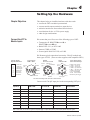
Configuring Your
SLC Processor, Off-line
This procedure assumes you are using RSLogix500 Programming Software, version 2.10 or later. For other software, the procedure may vary.
1. Open your 1746-QV project, VELMOD.
2. Configure the type of SLC processor. To do this:
A. Open the file, Controller Properties.
B. Select the SLC processor type and click OK.
3. Configure the rack size, module slot, and module ID:
A. Open the file, I/O Configuration.
B. Select the rack size.
C. Highlight the slot number for the module.
D. From the list of modules, scroll to 1746-QV and double–click.
If the module is not listed:
– Scroll to Other and double-click.
– Enter the module’s ID (13115) and double-click.
4. Size the “G” file:
A. Highlight 1746-QV (or 13115 if module was not listed).
B. Click [Adv Config].
C. In the dialog box, enter a G-file length of 7.
D. Press [Edit G Data].
Publication 1746-6.18 April 1998
Setting Up the Software
3–3
5. Enter values in the G file:
If the module was listed:
If the module was not listed (you entered the ID):
You get the G–file Setup screen.
Enter data from the table, below.
You get the following display, shown in decimal radix.
Enter a value in each word as shown, next.
G–file display for unlisted module (shown in decimal radix):
Ge:0
2056
0
0
0
0
0
0
Enter a value at each G-file word address and press [ENTER].
Then cursor to the next word address and repeat. For example:
Ge:0
2056
893
730
12
1200
–32768
0
We used values from the ladder logic example (appendix B).
You will want to use G-file values that suit your application:
Word: Function of G-file Word:
0
Reserved. Do NOT use.
Range:
Description of G-file Word or Bit:
Example:
n/a
The processor stores a code for the 1746-QV module.
2056
words 1 & 2 refer to the gradient or transducer calibration value stamped on the name plate on the transducer housing.
For eexample:
a ple Too enter an LDT calibration of 8.9373
8.9373,
1
LDT calibration: upper 3 digits 800-999 ms/inch
u
use
e
deci
decimal
al
radi
radix
and
enter
893
in
word
1
and
73 in word 2.
730
2
LDT calibration: lower 3 digits 000-999 ms/inch
3
Full-scale length (L) of LDT
2vLv160 inch
Enter the length of the LDT (160 inches max).
893
730
12
4
Full-scale count (C)
2vCvLx100
Typically C = L x 100.
1200
Position Data (I:e.1) =
5
Configuration Bits
Bit
15 14 13
0 1 0
1 0 0
1 1 0
0 1 1
6
12-0 Equivalent Value
0
+16,384
0
–32,768
0
–16,384
0
+24,576
Preset Reference
bits 0-12
bit 13
C/(L x 100)
LDT Calibration
Set to zero.
0 = output maintained during LDT fault while running profiles and
during SLC mode change
1 = output resets for LDT fault and SLC mode change
bit 14
bit 15
Type of LDT: 0 for RPM, 1 for DPM
0 = position data increases when moving away from LDT head
1 = position increases when moving toward LDT head
–32,768 to +32,767 Typically zero or home reference value. 32,767 = 327.67 inches.
–32,768
(bit
bit 15
1 =1
for position
increases
towards
LDT head)
head
0
Examples of Full-scale Count Values
LDT Physical
Length
No. of
Recirculations
Full-scale
Resolution Length (L)
Full-scale
Counts (C)
from 160” to 2”
1
0.01
L (160” to 2”)
L x 100
16”
2
0.01
160
8000
16”
4
0.01
160
4000
16”
10
0.001
160
16000
Important: The module checks for invalid data such as out of
range values or the setting of reserved bits 0-12. You can clear a
data-entry configuration error only by re-entering a corrected value.
6. Save when done.
Click OK. Click OK. Close window.
Publication 1746-6.18 April 1998
3–4
Setting Up the Software
Modify N Files in Your
SLC Processor, Off-line
One N file may contain the initial commands, setpoints, and values
for configuring the extend and retract profiles.
A set of profile data
for initial configuration
Retract Voltages
Retract Positions
Extend Voltages
Extend Positions
>>>
>>>
Command
and
Setpoints
1746-QV Module
Output Image Table
>>>
>>>
>>>
Command
and
Setpoints
>>>
>>>
>>>
Extend
and Retract
Profiles
The file contains commands and data starting at the these addresses:
• command and position setpoints for extend
#N7:0
• command and voltage (velocity) values for extend #N7:10
• command and position setpoints for retract
#N7:20
• command and voltage (velocity) values for retract #N7:30
The sample ladder program (appendix B) copies profile data into the
output image table from the above locations.
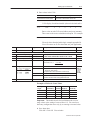
Output Image Table with Profile Data
Word: Function of Output Image Word:
0
Bit #: Description: (For command bits, a 0-to-1 transition enables the command)
0
1
2
3
Command
Co
and Bits
Bit
Enable these
the e bits
bit (O:e.0/bit
e. /bit #)
with your
logic, where e
our ladder logic
represents the I/O slot number.
1-7
Position Setpoint or Voltage Value
4
5
6
7
8
9-15
n/a
Set to run an extend profile.
Set to run a retract profile.
Set to disable the profile. This bit over-rides bit 0 or 1.
Set to change the current position data to the value of the preset reference
stored in Ge:6.
Set to clear any data-entry errors.
Set to define words 1-7 as programmed position setpoints for extend.
Set to define words 1-7 as programmed voltage values for extend.
Set to define words 1-7 as programmed position setpoints for retract.
Set to define words 1-7 as programmed voltage values for retract.
Reserved. Do NOT use.
Important: Position setpoints are in units of 0.01” (200 = 2.00”)
within the range of –327.68” to +327.67”, and voltage values in
5mV units (3005 = 3.005V) within the range of "10,000mV.
The data monitor mode of your programming software displays the
data files shown below (with values from the ladder program).
Important: Modify these values to suit the preset reference chosen
for the G file and/or to match the LDT length.
Extend Positions:
Extend Velocities:
Retract Positions:
Retract Velocities:
N7:0
N7:10
N7:20
N7:30
Publication 1746-6.18 April 1998
32
64
128
256
–45
3000
–45
5000
50
3750
50
6000
200
4000
200
6000
300
4000
300
3000
400
4000
400
1000
425
4000
425
50
500
4000
500
25
0
0
0
0
0
0
0
0
Setting Up the Software
General Conventions
for Profiles
3–5
Consider the following when you set up your profiles:
• Extend and retract define the profile with respect to the LDT head:
extend is always away from the head, retract is always towards it
• Position data changes direction depending on how you set
configuration bit Ge:0/15 for LDT motion:
0 = position data increases when moving away from LDT head
1 = position data increases when moving towards LDT head
• Each position setpoint triggers from the absolute position data
(I:e.1) as modified by the preset reference.
• Position setpoints are in units of 0.01”.
For example, enter 2” as 200.
• If you enter position setpoints in random order, the module places
them in ascending order (P1 = lowest and P7 = highest) with their
associated voltage value.
• Speed segments are defined increasing from the LDT head,
regardless of position data direction.
• Speeds are reported in the input image table words 2-7 (I:e.2-I:e.7)
for the previous profile (extend speeds reported during the next
retract profile and vice versa)
• Voltage values (for speed) are in the range of "10,000mV in
multiples of 5mV. For example, enter –5.005V as –5005.
Important: Enter voltage values in multiples of 5mV or the module
will fault, causing you to correct and re-download the profile.
• Voltage values are cleared when you re-program position
setpoints. The profile is cleared when the module loses power or
when you change the value of any G-file configuration word.
Important: Your application may require different position setpoints
and voltage values. Your profiles must be consistent with the physical
parameters of the LDT and G file to guard against damaging hardware.
Profile Operation
In general:
• For relatively faster and smoother motion, use two speed segments
for acceleration and five speed segments for deceleration.
• Adjust the ramp rate on the proportional amplifier for the smoothest
operation. Initially, start with the ramp disabled (fastest ramp rate).
• You may compensate for deadband or valve overlap by specifying a
voltage value greater than or equal to the valve’s bias current.
Profile operation depends on how the module reports position data.
With the data-direction bit (Ge:0/15), you select whether:
– position data increasing towards the LDT head (Ge:0/15 = 1)
– position data increasing away from the LDT head (Ge:0/15 = 0)
Publication 1746-6.18 April 1998
3–6
Setting Up the Software
For Position Data Increasing Towards LDT Head (Ge:0/15 = 1)
Voltage
Output = 0
past position 1
Position
V1
Speed
Segment 6
V2
V3
V4
V5
V6
V7
Speed
Speed
Speed
Speed
Speed
Segment 5 Segment 4 Segment 3 Segment 2 Segment 1
LDT
head
P1
P2
P3
P4
P5
P6
P7
• Starting with the ram between P7 and the LDT head (open position),
running the extend profile results in V7 applied to the output.
As the ram passes below P7, V6 is applied to the output, etc.
• If the ram passes below P1, the output is forced to 0V dc, and the
profile is disabled. You must load new data to operate the profile.
• Placement operations require two segments.
For example, if P2 = 6.07”, V2 = 1.500V, P1 = 0.00” (or a value
less than P2), and V1 = –1.500V, then the module will place the
ram in the vicinity of P2 (between 6.02 and 6.12). The negative
voltage V1 causes motion to reverse or stop. To see this, enter the
example values for P2, V2, P1, and V1 in the previous diagram.
Position Data Increases from LDT Head (Ge:0/15 = 0)
Voltage
Output = 0
past position 7
V7
Speed
Segment 6
V6
V5
V4
V3
V2
V1
Speed
Speed
Speed
Speed
Speed
Segment 5 Segment 4 Segment 3 Segment 2 Segment 1
LDT
head
Position
P7
P6
P5
P4
P3
P2
P1
• Starting with the ram between P1 and the LDT head (open position),
running the extend profile results in V1 applied to the output.
As the ram passes P1 towards P2, V2 is applied to the output, etc.
• If the ram passes P7, the output is forced to 0V dc, and the extend
profile is disabled. You must load new data to operate the profile.
Publication 1746-6.18 April 1998
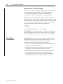
Setting Up the Hardware
Chapter Objectives
This chapter helps you install the hardware with these tasks:
•
•
•
•
•
Connect the LDT to
Module Inputs
connect the LDT to module input terminals
connect module output terminals to output devices
minimize interference from radiated electrical noise
considerations for the "15V dc power supply
other design considerations
We assume that you will use one of the following types of LDT:
• Temposonics II: RPM TTSRxxxxxxR, or
DPM TTSRxxxxxxDExxx
• Balluff: BTL-2-L2, or BTL-2-M2
• Santest: GYRP, or GYRG
• Gemco Quick-Stick II: 951VP, or 951 RS
We illustrate typical connections between the 1746-QV module and
these types of LDTs. (There are other suppliers with compatible LDTs.)
1746-QV Module
Input Terminal Block
8
7
6
5
4
3
2
1
Temposonics II,
RPM or DPM
PS
(+) Gate Out
Common
Interro(–) Gate Out
gate
(–) Interrogate
1
(+)
(+) (–)
(+) Interrogate
Frame
9 7 5 3 2
Shield/Frame
GND
10 8 6 4
–15V dc PS
(–) (+)
PS Common
(–)
Gate Out
+15v dc PS
"15V dc PS
Balluff
BTL-2-L2 & -2-M2
Interro- Gate Out (–)
Gate Out (+)
gate (–)
2
5
4
(–)
8
3
1
7 (+)
"15V
dc PS
6
Interrogate (+)
PS
Common
Santest
GYRP & GYRG
NC
+15V
dc PS
2
1
Gemco Quick-Stick II
951VP w/PWM Output
PS
Common
3
4 (+)
5
7
6 (–)
Gate
Gate
Out (+)
Out (–)
Interrogate
B–BLK PS Common
C–RED +15V dc PS
K–GRY + Interrogate
E–BRN –Sq Wave Out*
F–BLU +Sq Wave Out*
A–WHT –Interrogate
G, D, H RS232RXD
J–PUR 2nd PS COM
*951RS has pulse trigger
The views are looking at the connector on the LDT head.
Connect each 1746-QV input pin # to the corresponding LDT pin #.
1746-QV
Function
Input Pin #
Temposonics II
RPM or DPM
Balluff
BTL-2-L2 & -M2
Santest
GYRP/GYRG
Gemco QuickStick 951VP/RS
8
(+) Gate Out
4 – Pink
2 – Gray (note 1)
pin 5
F – Blue (note 1)
7
(–) Gate Out
3 – Gray
5 – Green (note 1)
pin 7
E – Brown (note 1)
6
(–) Interrogate
10 – Green
3 – Pink
pin 6
A – White
5
(+) Interrogate
9 – Yellow
1 – Yellow
pin 4
K – Gray
4
Shield/Frame
n/a
n/a
n/a
n/a
3
–15V dc PS
6 – Blue
8 – White
n/a
n/a
2
PS Common
1 – White
6 – Blue
pin 3
B – Black
1
+15V dc PS
5 – Red
7 – Brown
pin 1
C – Red
(+) and (–) wires of the same function should be a twisted pair within the cable.
Note 1: In the table, we use the term “gate out” for pulse trigger or square wave (Gemco) and start/stop (Balluff -M2) LDT signals.
Publication 1746-6.18 April 1998
4–2
Setting Up the Hardware
Connect Module Outputs
to Output Devices
Module outputs connect to a separate 2-conductor output terminal
block located beneath the input terminal block.
+24V dc PS
0V dc PS
1746-QV Output
Terminal Block
2
1
Analog Output
("10v dc)
Servo Amplifier
(Proportional)
(+) Diff.
(–) Input
0V
Outputs A
to valves B
Important: Ground the shield of the amplifier
output cable to a 0V connection in the amplifier.
Do not connect the shield to earth ground.
To solenoid A
To solenoid B
Note: Follow manufacturer recommendations for shielding the output
cables of the proportional amplifier. Typically, pulse-width modulated
outputs radiate electrical noise originating from the +24V dc power
supply, so isolate the shields of the amplifier output cable to a 0V dc
connection inside the proportional amplifier.
You have a choice of three configurations to match your hydraulics:
• proportional amplifier with ramp and proportional valve
• servo amplifier with ramp and variable-volume pump
• Allen-Bradley 1305 Drive and hydraulic pump
You may use either of the following output voltage ranges:
• 0-10V dc for the Allen-Bradley 1305 Drive or variable-volume pump
• –10 to +10V dc for the proportional amplifier and proportional valve
Minimizing Interference
from Radiated Electrical
Noise
Important: Signals in this type of control system are very susceptible
to radiated electrical noise. The module is designed to set the loss-ofsensor bit I:e.0/8 and the LDT-error bit I:e.0/0 when it detects position
values that are lost or corrupted by electrical noise.
Connect module output terminals to output devices with correct bonding:
• connect power supply output commons together
• electrically isolate power supply output commons from earth ground
• use bond wires that are equal in size to signal wires
Minimize interference from radiated electrical noise with correct
shielding and grounding:
• connect all of the following to earth ground:
– LDT flange, frame, and machine
– I/O chassis
– protective ground
– AC ground
– cable shields at one end only, preferably with 3/8” braid wire
(for analog output, "15V dc PS, 24V dc PS, and LDT)
– terminal 4 of the input terminal block
Publication 1746-6.18 April 1998
Setting Up the Hardware
4–3
• run shielded cables only in low-voltage conduit
• place the SLC-500 processor, power supply, and I/O chassis
assembly in a suitable enclosure
Typical grounding and shielding for this type of control system:
"15V Power
Supply
(+) (C) (–)
1746-QV
Module
Case
GND
24V Power
Supply
(–) (+)
Case
GND
Input
LDT
Power
1
2
3
LDT
Signals
5-8
Belden
8770
Belden
8761
4
Analog Output
Output
0V
Belden
8761
Servo
Proportional
Amplifier
Case
GND
Cable
Note
earth ground
Piston-type Hydraulic Cylinder and
Linear Displacement Transducer (LDT)
Valves
LDT and Hydraulic Ram
Cable Note: Use cable
recommended by the LDT
and amplifier manufacturer.
Cable
Note
Considerations for the
"15V dc Supply
Selection of the "15V Power Supply
The positive and negative supply of some "15V dc power supplies
decay at different rates when ac power is removed. The module’s
output will be biased, based upon the difference in voltage level
between the positive and negative supply. The duration is dependent
upon the magnitude of the difference and the decay rate. For these
reasons, the "15V dc power supply should have or be equipped with:
• proper interlocks with machine operation and e-stop circuits
• an internal voltage-sense relay that drops the "15V (without
variation in decay rates) upon loss of ac power
• auxiliary relay to indicate proper operation and voltage
(such as loss of +15V but not –15 V dc)
Power Supply Loading
The module and LDT load the power supply typically as follows:
Supply
+15V dc
No Transducer
No Load
86mA
Transducer
Only *
128mA
–15V dc
14mA
30mA
LDT + Module:
LDT + Module:
+10V dc @ 10mA –10V dc @ 10mA
141mA
128mA
30mA
40mA
*MTS Temposonics II, model T1SR0U0120R (Other LDTs will have different loading.)
Publication 1746-6.18 April 1998
4–4
Setting Up the Hardware
Application of the "15V Power Supply
The module uses the "15V dc power supply to drive the "10V dc
valve output and to power the LDT. The module detects loss of
"15V dc with its internal LDT diagnostic. The diagnostic
concludes loss of "15V when it detects loss of LDT magnet.
Partial failure of the "15V dc power supply may cause limited
machine operation when the LDT continues to operate properly. Some
LDTs will operate with its supply voltage down to 12V. If you monitor
the "15V dc with SLC diagnostics, you can enable a blocking valve
to lock the actuator in its last position upon detection of:
• e-stop
• power loss
• low voltage condition of the "15V dc supply
ATTENTION: If you provide a system e-stop circuit and design the
system to manage power to the SLC chassis and "15V dc supply, in
all cases DO NOT connect the e-stop to ac power for power supplies.
Other Design
Considerations
ATTENTION: We recommend using reasonable methods to assure
that unintended motion does not cause machine damage or create a
safety issue with personnel who will operate the machine.
(Chapter 5 covers testing for proper system operation.)
• Use a proportional valve that does not respond to voltage spikes
created by power supply operation.
• Shut down the hydraulic system upon loss of ac power and
automatically vent pressurized fluid back to the tank.
• Provide ladder programming that interlocks the operation of the
power supply with permissives to run the hydraulic pump.
• Connect a high-speed relay between the module and the valve
amplifier to drop-out the valve signal upon loss of ac power.
Publication 1746-6.18 April 1998
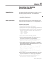
Operating the Module
for the First Time
Chapter Objectives
This chapter outlines the steps for operating the module for the first
time with an operating hydraulic ram. We cover these steps:
• power-up the system
• test for proper system operation
• troubleshoot possible problems
Power Up the System
Starting with module and LDT power turned off, bring the system
on-line for the first time as follows (refer to I/O wiring in chapter 4):
Check Wiring and Grounding
1. Disconnect the LDT connector at the head end.
2. Disconnect both of the module’s input and output terminal blocks.
3. Turn ON the power supplies for the LDT and SLC processor, and
check the LDT connector and module input terminal block for:
• pin 1
• pin 2
• pin 3
+15V dc
PS common
–15V dc
4. Observe that the module’s fault LED (red) is ON.
5. Verify NO continuity between pin 2 (PS commons) and pin 4
(shield/frame) on the module’s input terminal block.
6. Verify NO continuity between the LDT cable shield and pin 2
(PS commons) on the module’s input terminal block.
7. Verify continuity between pin 2 (PS commons) on the module’s
input terminal block and the output common on the "15V dc PS
that powers the LDT and module.
8. Verify continuity between pin 2 (PS commons) on the module’s
input terminal block and the (–) terminal on the +24V dc PS
that powers the proportional amplifier.
9. Verify NO continuity between the +24V dc PS (–) connection
and earth ground.
10.Verify continuity between the shield of the amplifier output cable
and pin 2 (PS commons) on the module’s input terminal block.
11. Verify continuity between the cable shield (Belden 8761 or
equivalent) on the +24V dc PS and earth ground.
Publication 1746-6.18 April 1998
5–2
Operating the Module
Get Ready to Move the Ram
1. Turn on the +24V dc PS that powers the amplifier.
2. Turn on the hydraulic pump and “null” the ram for no movement.
3. Turn off all power supplies.
4. Connect the LDT cable and input terminal block.
5. Turn on all power supplies.
6. Be sure that you have loaded the extend and retract profiles into
the module.
7. Observe module LEDs. The RUN LED (green) should be blinking.
If not blinking, refer to troubleshooting covered last in this chapter.
Module LEDs indicate the following to assist you with the procedures:
This LED:
Is:
When the Module detects:
Flashing
output is at 0V dc
profiles are loaded and output is active
ON
OFF
no internal faults
FAULT
FA
red
(red)
an LDT fault
Flashing
ON
an internal fault
For Series A Revision A: During startup, Run LED ON and Fault LED
flashing indicate outputs are at 0V dc. During profiles, Fault LED is OFF.
RUN
N
(green)
green
8. Observe that the output image table word 0 (O:e.0) is zero.
If not zero, toggle the value of N7:50 from 0 to 16 to 0.
Reload the profiles by entering the value of 1 into N7:40.
If profiles do not reload, refer to Troubleshooting on page 5-4.
9. With the output terminal block still disconnected, run the extend
profile by changing the value in N7:50 to 1. The RUN LED should
change to ON. If not, refer to troubleshooting covered last.
Important: Reset the value in N7:50 to 0.
10.Connect the output terminal block.
Move the Ram
Important: When you set an output bit with your programming
terminal, the commanded action takes place immediately.
1. Run the extend profile by momentarily changing the value in
N7:50 to 1, and observe the direction of ram movement in N7:61.
If the ram moves in the wrong direction:
If using this type of valve and signal:
Then reverse the:
proportional valve with "10V input
sign (") of all voltage values and load them into the module
hydraulic motor or ac drive with 0-10V input other solenoid on the directional valve (with ladder logic)
Publication 1746-6.18 April 1998
Operating the Module
5–3
2. After reversing the sign of voltages (if needed), run the extend
profile again by changing the value in N7:50 to 1.
Observe that the direction of ram travel is correct.
Important: Reset the value in N7:50 to 0.
3. Check the position value reported in the status word, N7:61, as
you run the ram to the end of its travel. If the position data is
reversed, you may need to change the data-direction bit (Ge:5/15)
in the G file off-line as follows:
• 0 = position increases while moving away from LDT head
• 1 = position increases while moving toward LDT head
Important: You must reload profiles for either of these conditions:
• Changing a value in the G file. (This clears the profiles).
• When position data exceeds the position setpoint that is
farthest from the LDT head, the profile is disabled and
you must modify position setpoints and reload the profiles.
4. Verify operation of the retract profile by changing the value in
N7:50 to 2. Important: Reset the value in N7:50 to 0, afterwards.
Jog the Ram to the Reference Position
The reference position may require that you jog the ram beyond a
position defined by the profile in the ladder program (appendix B).
You may jog the ram as follows:
1. Observe the current position data (in I:e.1).
2. Modify profile position setpoint(s) to permit the ram to travel to the
required reference position using the current position. For example:
If position data reads –100, change P1 to –1300 (length of the LDT)
3. Important: Reset the value in N7:50 to 0.
Load the profiles into the module.
4. Run the extend profile by changing the value in N7:50 to 1, and
jog the ram to the reference position.
5. At the reference position, the position data, I:e.1, (N7:61) will be an
arbitrary value. Set the position data to the value of the preset
reference by changing the value in N7:50 to 8 (N7:40 must = 0).
Position data will change to preset reference (0 in this example).
6. Verify that N7:61 now reads zero at the reference position.
Important: Once you establish the reference position:
• the module will maintain the preset reference’s position data in I:e.1
• all profile position setpoints will be referenced to it
(until you clear Ge:6 by changing any G-file value or set another
reference position. The preset reference is retained during power up.
Publication 1746-6.18 April 1998
5–4
Operating the Module
Test for
Proper System Operation
ATTENTION: Test for proper system operation to verify that
precautions to guard against unexpected motion perform as intended.
(See Power Supply and Design Considerations in chapter 4)
Because of the wide variety of applications for this module, we leave
the procedural details to you.
Look for proper system operation as you test for these conditions:
• controlled system startup/shutdown when turning hydraulics on/off
• startup/shutdown of ac to power supplies
("15V dc, SLC chassis, and 24V dc)
• loss of LDT input
• effect of the last-state-of-output bit (G-file, word 5, bit 13)
regarding one or more of the above
Troubleshoot
Possible Problems
Using Status Bits for Errors Detected by the Module
The module is designed to detect and indicate status as follows
(in the input image table word I:e.0 or N7:60 in the ladder program):
• hardware operational faults
• data entry errors when entering setpoints or setting control bits
• acknowledgement of stored setpoints
Important: To clear error bits, toggle N7:50 from 0 to 16 to 0.
Bit #: Description: (for error & fault bits 0-8, status of 0 = OK, status of 1 = fault.)
0
The module sets this LDT error bit when it detects a:
– broken or mis-wired LDT cable
– faulty LDT
– incompatible LDT type (DPM or RPM)
– missing LDT magnet
– loss of "15V dc PS
1
Module fault, such as EEPROM error. May turn outputs OFF (fault dependent)
2
The module sets this bit when it detects any of the following invalid command bits
or bit combinations in output image table word 0 (O:e.0):
– one or more of the reserved bits 9-15 were set
– bit 5 or 7 (position) was set concurrently with bit 6 or 8 (voltage)
– output enable bit 0 (extend) or 1 (retract) was set before loading valid profiles
– both output enable bits 0 (extend) and 1 (retract) were set concurrently
– started to run a profile after the module had flagged an LDT error (I:e.0/0)
3
You set one or more of the reserved bits 0-13 in G-file word 5 (Ge:5).
4
You entered an invalid length (word 3) or count (word 4) in the G file.
5
You entered an invalid LDT calibration (words 1 and/or 2) in the G file.
6
You entered position setpoint outside the range –32,768 to +32,767 in O:e.1-O:e.7.
7
You entered a voltage value outside the range of "10,000mV in O:e.1-O:e.7.
8
Loss of sensor. The module detected position data (in I:e.1) greater than the LDT
length plus the preset reference. Clear this bit by running a profile.
Reserved. Do NOT use.
9-11
Publication 1746-6.18 April 1998
Operating the Module
Bit #:
12
13
14
15
5–5
Description: (for error & fault bits 0-8, status of 0 = OK, status of 1 = fault.)
The module sets this bit after it stores retract position setpoints or voltage values,
or when retract profile is active. It remains set until another operation is performed.
The module sets this bit after it stores your position setpoints.
It resets it after you reset the “program position” bit (O:e.0/5 or O:e.0/7)
The module sets this bit after it stores your voltage values.
It resets it after you reset the “program voltage” bit (O:e.0/6 or O:e.0/8)
The module sets this bit when it detects the profile is active (output is applied).
Troubleshooting Table
If you observe this condition:
Try this solution:
Refer to this part of the manual:
Sensor signal (N7:61)
ha
ign ()..
has wrong sign
1. Change direction bit (Ge:5/15) and re–download.
a) Enter values in G file, page 3-3.
b) Move the Ram, step 3, page 5-3.
2. Calibrate the sensor at opposite end of cylinder.
Re-do Jog Ram to Reference, pg 5-3.
After download, sensor values do not
match values in N7:61 before download.
After axis calibration (preset ref = set, and N7:50 = 8),
you must upload and save SLC data files in the PC.
none
Module re
rejects
ect prepre-set
et reference when
N7 is
N7:50
i toggled from
fro 0 to 8 to 0..
1. Pre-set Ref in G file must be within profile range.
Enter values in G file, page 3-3.
2. N7:40 must = 0 when setting N7:50 = 8.
Re-do Jog Ram to Reference, pg 5-3.
1. Each profile setpoint must be within sensor’s range.
Verify full-scale count in Ge:4, page 3-3.
2. Clear any errors by toggling N7:50 (0 to 16 to 0)
Prior to step 8 in Get Ready to Move Ram.
3. N7:40 must = 0 when setting pre-set reference
with N7:50 = 8.
Jog Ram to Reference, step 5, pg 5-3.
Profiles will not load into the module.
Profile
odule.
Unable to initiate extend/retract profiles.
Write ladder rung for extend profile, another for retract. none
Each must include appropriate permissives to enable
a MOV instruction with Source (1 = extend, 2 = retract)
and Destination = N7:50.
Conditions That Control Module Outputs
The module is designed to control its outputs as follows:
The module is designed to:
When these conditions are satisfied:
apply profile voltages
to the output
all of the following:
– valid extend and retract profiles are stored in the module
– the “stop profile” bit (O:e.0/2) is reset.
– a “run profile” bit (O:e.0/0 or O:e.0/1) is set
retain its outputs
in last state
any of the following:
– loss of backplane power ("15V dc PS remains applied)
– loss of sensor (LDT)
– SLC mode change or LDT fault (G:e:0/13 = 0)
any of the following:
– LDT position exceeded the setpoint farthest from LDT head
– loss of "15V dc PS
– the “disable output” bit (O:e.0/2) is set
– SLC mode change or LDT fault (G:e:0/13 = 1)
turn OFF its outputs
Publication 1746-6.18 April 1998
5–6
Operating the Module
Notes:
Publication 1746-6.18 April 1998
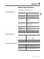
Module Specifications
This appendix lists the specifications for the
1746-QV Open-loop Velocity Control Module.
Electrical Specifications
Power Requirements
215 mA at 5V dc (from backplane)
400 mA at +15V dc and 295 mA at –15V dc
(from independent PS, typical but LDT dependent)
I/O Chassis Location
Any I/O-chassis slot except slot 0
Isolation
1500V ac optical isolation
between LDT input and backplane
LDT Inputs
"Interrogate
"Gate
"15V dc PS
PS Common
Shield/Frame
Compatible LDT Input Devices
Linear Displacement Transducer such as:
Balluff BTL-2-L2 or -M2
Gemco Quick-Stick II
Santest GYRP or GYRG
Temposonics II with DPM or RPM
Module Range
and Resolution
160 inches
"0.01 inch
Analog Output
0-10V dc @ 250 mA or
–10 to +10V dc @ 250 mA
Accuracy of Voltage Output
Within "1% of its programmed value
Module Update Time
2 ms
Physical Specifications
LED Indicators
Run
(green):
ON
Flashing
Profile running, Output active
Output at 0V dc
Fault
(red):
OFF
Flashing
ON
Module OK
LDT fault
Module fault
Module ID Code
13115
Maximum Wire Size
Two 18 AWG wires per terminal on terminal block
Operating Temperature
0°C to 60°C (32°F to 140°F)
Storage Temperature
–40°C to +85°C (–40°F to +185°F)
Relative Humidity
5% to 95% (without condensation)
Agency Certification
(when marked on
product or package)
CE marked for all applicable directives
Environmental Specifications
Publication 1746-6.18 April 1998
A–2
Module Specifications
Notes:
Publication 1746-6.18 April 1998
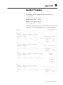
The following data define extend and retract profiles for the
sample program:
Extend position setpoints
Extend voltage values
Retract position setpoints
Retract voltage values
#N7:0
#N7:10
#N7:20
#N7:30
This ladder program loads profiles into the module through the output
image table. (The 1746-QV module is in slot 1 for this example.)
Rung 2.0
Program Profile |
|
S:1
N7:40
|
|–––] [––––––––––––––––––––––––––––––––––––––––––––––––––––––––––––––(L)–––––––+
|
15
0
|
|
Rung 2:1
|
| Set to
|Extend
|Positions |Voltages
|
| program |profile |stored
|stored
|
| profile |complete
Extend Position Setpts. |
|
|
| N7:40
N7:8
I:1.0
I:1.0
+COP–––––––––––––––+ |
|–––] [–––––––––]/[–––––––]/[––––––––]/[––––––––––––––––––+COPY FILE
+–|
|
0
0
13
14
|Source
#N7:0| |
|
|Dest
#O:1.0| |
|
|Length
8| |
|
+––––––––––––––––––+ |
Rung 2:2
| Set to
|Extend
|Positions |Voltages
|
| program |profile |stored
|stored
|
| profile |complete
Extend Velocity Setpts. |
|
|
| N7:40
N7:8
I:1.0
I:1.0
+COP–––––––––––––––+ |
|–––] [–––––––––]/[–––––––] [––––––––]/[––––––––––––––––––+COPY FILE
+–|
|
0
0
13
14
|Source
#N7:10| |
|
|Dest
#O:1.0| |
|
|Length
8| |
|
+––––––––––––––––––+ |
Rung 2:3
| Set to
|Extend
|Run/store |Positions |Voltages
Extend
|
| program |profile |retract
|stored
|stored
profile
|
| profile |complete
complete
|
|
|
| N7:40
N7:8
I:1.0
I:1.0
I:1.0
N7:8
|
|–––] [–––––––––]/[–––––––]/[––––––––]/[––––––] [––––––––––––––––+––––(L)––––+–|
|
0
0
12
13
14
|
0
| |
|
| Program
| |
|
| extend
| |
|
| voltages | |
|
|
O:1.0
| |
|
+––––(U)––––+ |
|
6
|
Rung 2:4
| Set to
|Extend
|Positions |Voltages
|
| program |profile |stored
|stored
|
| profile |complete
Retract Position Setpts.|
|
|
| N7:40
N7:8
I:1.0
I:1.0
+COP–––––––––––––––+ |
|–––] [–––––––––] [–––––––]/[––––––––]/[––––––––––––––––––+COPY FILE
+–|
|
0
0
13
14
|Source
#N7:20| |
|
|Dest
#O:1.0| |
|
|Length
8| |
|
+––––––––––––––––––+ |
Publication 1746-6.18 April 1998
B–2
Ladder Program
Rung 2:5
| Set to
|Extend
|Run/store |Positions |Voltages
|
| program |profile |retract
|stored
|stored
|
| profile |complete
Retract Velocity Setpts.|
|
|
| N7:40
N7:8
I:1.0
I:1.0
I:1.0
+COP––––––––––––+ |
|–––] [–––––––––] [–––––––] [––––––––] [––––––]/[––––––––––––+COPY FILE
+–|
|
0
0
12
13
14
|Source
#N7:30| |
|
|Dest
#O:1.0| |
|
|Length
8| |
|
+–––––––––––––––+ |
Rung 2:6
| Set to
|Extend
|Run/store |Positions |Voltages
Retract
|
| program |profile |retract
|stored
|stored
profile
|
| profile |complete
complete
|
|
|
| N7:40
N7:8
I:1.0
I:1.0
I:1.0
N7:8
|
|–––] [–––––––––] [–––––––] [––––––––]/[––––––] [––––––––––––––––+––––(L)––––+–|
|
0
0
12
13
14
|
1
| |
|
| Program
| |
|
| retract
| |
|
| voltages | |
|
|
O:1.0
| |
|
+––––(U)––––+ |
|
8
|
Rung 2:7
| Set to
|Extend
|Retract
Loading
|
| program |profile |profile
profiles
|
| profile |complete |complete
complete
|
|
|
| N7:40
N7:8
N7:8
N7:40
|
|–––] [–––––––––] [–––––––] [––––––––––––––––––––––––––––––––––––+––––(U)––––+–|
|
0
0
1
|
0
| |
|
| Extend
| |
|
| Profile
| |
|
| Complete | |
|
|
N7:8
| |
|
+––––(U)––––+ |
|
|
0
| |
|
| Retract
| |
|
| Profile
| |
|
| Complete | |
|
|
N7:8
| |
|
+––––(U)––––+ |
Rung 2:8
1
| Set to
|
| program
|
| profile
|
|
|
| N7:40
+COP–––––––––––––––+
|
|–––]/[–––––––––––––––––––––––––––––––––––––––––––––––+–+COPY FILE
+–+–|
|
0
| |Source
#I:1.0| | |
|
| |Dest
#N7:60| | |
|
| |Length
8| | |
|
| +––––––––––––––––––+ | |
|
|
| |
|
| +MOV–––––––––––––––+ | |
|
+–+MOVE FILE
+–+ |
|
|Source
N7:50 |
|
|
|
0 |
|
|
|Dest
O:1.0 |
|
|
|
0 |
|
|
+––––––––––––––––––+
|
Rung 2:9
|–––––––––––––––––––––––––––––––––––+END+––––––––––––––––––––––––––––––––––––––+
Extend Positions
Extend Voltages
Retract Positions
Retract Voltages
G-file for Module
Configuration
Address
#N7:0
#N7:10
#N7:20
#N7:30
Data (radix = DECIMAL)
32
–45
50
200
64
3000
3750
4000
128
–45
50
200
256
5000
6000
6000
G1:0
2056
Publication 1746-6.18 April 1998
SLC Code for
QV Module
890
640
LDT Calibration
300
4000
300
3000
12
1200
Length
Counts
400
4000
400
1000
425
4000
425
50
–32,768
500
4000
500
25
0
Config Word 5
Preset
bit 15=1
Reference
(position increases
toward LDT head)
0
0
0
0
0
0
0
0
SLC Processor Files
You use the following files when programming the SLC processor
for an application with the 1746-QV module:
• input image table to indicate status
• G file to configure the module for its LDT
• output image table for commands and loading profiles
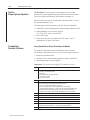
Input Image Table
Word 0 (I:e.0 or N7:60 in the ladder program) reports status such as
hardware faults, your data-entry errors, and acknowledgement of
profile data stored in the module. Word 1 reports position data.
Words 2-7 report speeds of the previous profile.
Word #: Bit #: Description: (for error & fault bits 0-8, status of 0 = OK, status of 1 = fault.)
0
0
1
2
3
4
5
6
7
8
9-11
12
13
14
1
2-7
15
n/a
n/a
The module sets this LDT error bit when it detects a:
– broken or mis-wired LDT cable
– faulty LDT
– incompatible LDT type (DPM or RPM)
– missing LDT magnet
– loss of "15V dc PS
Module fault, such as EEPROM error. May turn outputs OFF (fault dependent)
The module sets this bit when it detects any of the following invalid command bits or bit
combinations in output image table word 0 (O:e.0):
– one or more of the reserved bits 9-15 were set
– bit 5 or 7 (position) was set concurrently with bit 6 or 8 (voltage)
– output enable bit 0 (extend) or 1 (retract) was set before loading valid profiles
– both output enable bits 0 (extend) and 1 (retract) were set concurrently
– started to run a profile after the module had flagged an LDT error (I:e.0/0)
You set one or more of the reserved bits 0-13 in G-file word 5 (Ge:5).
You entered an invalid length (word 3) or count (word 4) in the G file.
You entered an invalid LDT calibration (words 1 and/or 2) in the G file.
You entered a position setpoint outside the range of –32,768 to +32,767 in O:e.1-O:e.7.
You entered a voltage value outside the range of "10,000mV in O:e.1-O:e.7.
Loss of sensor. The module detected position data (in I:e.1) greater than the LDT
length plus the preset reference. Clear this bit by running a profile.
Reserved. Do NOT use.
The module sets this bit after it stores the retract position setpoints or voltage values, or
when the retract profile is active. It remains set until another operation is performed.
The module sets this bit after it stores your position setpoints.
It resets it after you reset the “program position” bit (O:e.0/5 or O:e.0/7)
The module sets this bit after it stores your voltage values.
It resets it after you reset the “program voltage” bit (O:e.0/6 or O:e.0/8)
The module sets this bit when it detects the profile is active (output is applied).
Position data
Speed segments 1-6, respectively.
The module computes the speed of each segment and reports them in the subsequent
profile (reports extend speeds during the next retract profile, etc.)
Publication 1746-6.18 April 1998
C–2
SLC Processor Files
G File
Use this file (Ge:0) to configure the module for use with the LDT.
Example values are those from the sample ladder logic (appendix B).
Word: Function of G-file Word:
0
Reserved. Do NOT use.
Range:
Description of G-file Word or Bit:
Example:
n/a
The processor stores a code for the 1746-QV module.
2056
words 1 & 2 refer to the gradient or transducer calibration value stamped on the name plate on the transducer housing.
For eexample:
8.9373,
a ple Too enter an LDT calibration of 8.9373
1
LDT calibration: upper 3 digits 800-999 ms/inch
u
e
deci
al
radi
73 in word 2.
use
decimal
radix
and
enter
893
in
word
1
and
730
2
LDT calibration: lower 3 digits 000-999 ms/inch
3
Full-scale length (L) of LDT
2vLv160 inch
Enter the length of the LDT (160 inches max).
893
730
12
4
Full-scale count (C)
2vCvLx100
Typically C = L x 100.
1200
Position Data (I:e.1) =
5
Configuration Bits
1 14 13
15
0 1 0
1 0 0
1 1 0
0 1 1
6
12- Equivalent
Equi alent Value
12-0
0
+16,384
0
–32,768
0
–16 384
–16,384
0
+24,576
Preset Reference
C/(L x 100)
LDT Calibration
–32,768
bits 0-12
Set to zero.
bit 13
0 = output maintained during LDT fault or SLC mode change
1 = output resets for LDT fault or SLC mode change
bit 14
Type of LDT: 0 for RPM, 1 for DPM
bit 15
0 = position data increases when moving away from LDT head
1 = position increases when moving toward LDT head
bit 15
1 =1
(bit
for position
increases
increa
e
toward
towards
LDT head
head)
–32,768 to +32,767 Typically zero or home reference value. 32,767 = 327.67 inches.
0
Examples of Full-scale Count Values
Output Image Table
Command
Co
and Bits
Bit
Enable these
the e bits
bit
with your
our ladder logic.
1-7
Position 1-7 Setpoint or Voltage
(i.e. word 2 = position 2, etc.)
Publication 1746-6.18 April 1998
No. of
Recirculations
Full-scale
Resolution Length (L)
Full-scale
Counts (C)
from 160” to 2”
1
0.01
L (160” to 2”)
L x 100
16”
2
0.01
160
8000
16”
4
0.01
160
4000
16”
10
0.001
160
16000
The ladder program loads commands and profile data into the
module through the output image table, O:e.0–O:e.7.
Word: Function of Output Image Word:
0
LDT Physical
Length
Bit #: Description: (For command bits, a 0-to-1 transition enables the command)
0
1
2
3
4
5
6
7
8
9-15
n/a
Set to run an extend profile.
Set to run a retract profile.
Set to disable the profile. This bit over-rides bit 0 or 1.
Set to change current position data to the value of preset reference in Ge:6.
Set to clear any data-entry errors.
Set to define words 1-7 as programmed position setpoints for extend.
Set to define words 1-7 as programmed voltage values for extend.
Set to define words 1-7 as programmed position setpoints for retract.
Set to define words 1-7 as programmed voltage values for retract.
Reserved. Do NOT use.
Important:
Enter position setpoints in units of 0.01” (200 = 2.00”) within the range of
–327.68 to +327.67”, and voltage values in 5mV units (3005 = 3.005V)
within the range of "10,000mV.
A
I, J, K
access to BBS or Internet, 3-1, 3-2
ID of module, 3-2, A-1
applications of module, 1-2
input terminal block, of module, 4-1, 5-1
input image table (status), 5-4, C-1
B
Internet, access to, 3-2
BBS, Rockwell Software Bulletin Board, 3-1
benefits, of module, 1-2
bits
command, 3-4, C-2
G-file configuration, 3-3, B-2, C-2
status, 5-4, C-1
C
cables, 4-3
calibration (value) of LDT, 3-3, B-2, C-2
configure
G file, 3-3, B-2, C-2
motion profiles, 1-2, 3-4
SLC processor, 3-2
connections,
inputs to module, 4-1
outputs from module, 4-2
count, full-scale, 3-3
D
data direction (bit), 3-3, 3-5, 5-3, C-2
data, profile, 3-4, 3-5, B-2, C-2
download, from BBS, 3-1
L,M
ladder program, B-1
LDT
calibration value, 3-3
configuration in G file, 3-3
connections to, 4-1
fault, 5-2, 5-4
length of, 3-3
movement of, 3-5
types of, 4-1
LEDs, 5-2, A-1
N
N file, 3-4, 5-2, B-1
noise, electrical, 4-2
O
output
conditions, 5-5
connections, of module, 4-2, 5-1
image table, 3-4, C-2
terminal block, 4-2
status, 5-4
overview of module and system, 1-1
E
error, see fault
extend profile, 1-2, 3-4, 5-2, C-2
P
position data, 3-4, 3-5, 5-3, C-1
position setpoints, 3-4, 3-5, 5-2, 5-3, C-2
F
fault, module and LDT, 5-2, 5-4, C-1
G,H
G file, 3-2, 3-3, 3-5, 3-6, 5-3, B-2, C-2
grounding, 4-2, 4-3, 5-1
power supply, considerations, 4-3
preset reference, 3-3, 5-3
profile, 1-2, 3-3, B-1, C-2
conventions, 3-5
operation of, 3-5
I–2
Q
quick start, 2-1
R
ram, hydraulic, 1-1, 1-2
procedure to move, 5-2, 5-3
set reference position of, 5-3
reference, preset, 3-3, 5-3
retract profile, 1-2, 3-4, 5-3
reverse motion, 5-2
S
segments, speed, 1-2, 3-4, 3-5
(also see voltage values)
shielding, of cables, 4-2, 4-3, 5-1
specifications, of module, A-1
status (input image table) 5-4, C-1
of outputs, 5-4
system, power up, 5-1
T, U, V
testing, for proper system operation, 5-4
travel, length of LDT, 1-2, 3-3
troubleshooting, with
LEDs, 5-2
module status bits, 5-4
output conditions, 5-5
troubleshooting table, 5-5
voltage values, 3-4, 3-5, 5-2, C-2
W, X, Y, Z
wiring, system, 4-1, 4-2, 5-1
Publication 1746-6.18 April 1998
Allen-Bradley, a Rockwell Automation Business, has been helping its customers improve
productivity and quality for more than 90 years. We design, manufacture and support a broad
range of automation products worldwide. They include logic processors, power and motion
control devices, operator interfaces, sensors and a variety of software. Rockwell is one of the
world’s leading technology companies.
Worldwide representation.
Argentina • Australia • Austria • Bahrain • Belgium • Brazil • Bulgaria • Canada • Chile • China, PRC • Colombia • Costa Rica • Croatia • Cyprus • Czech Republic •
Denmark • Ecuador • Egypt • El Salvador • Finland • France • Germany • Greece • Guatemala • Honduras • Hong Kong • Hungary • Iceland • India • Indonesia •
Ireland • Israel • Italy • Jamaica • Japan • Jordan • Korea • Kuwait • Lebanon • Malaysia • Mexico • Netherlands • New Zealand • Norway • Pakistan • Peru •
Philippines • Poland • Portugal • Puerto Rico • Qatar • Romania • Russia–CIS • Saudi Arabia • Singapore • Slovakia • Slovenia • South Africa, Republic • Spain •
Sweden • Switzerland • Taiwan • Thailand • Turkey • United Arab Emirates • United Kingdom • United States • Uruguay • Venezuela • Yugoslavia
Allen-Bradley Headquarters, 1201 South Second Street, Milwaukee, WI 53204 USA, Tel: (1) 414 382-2000 Fax: (1) 414 382-4444
Publication 1746-6.18 April 1998
Supercedes Publication 1746-6.18 – February 1998
PN955132-83
Copyright 1998 Allen-Bradley Company, Inc. Printed in USA