1
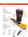
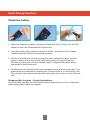
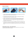
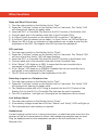
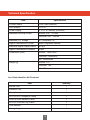
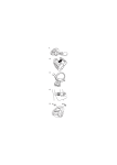
LAN Cable Identifier
Part No. 157012
Operating Manual
TRIAX - your ultimate connection
Contents
Product Profile
2
Cable Tracing Functions
3
Telephone Cables
3
Network Cables
5
Electrical Cables
7
Network Cable Continuity Function
8
Other Functions
9
Open and Short Circuit Test
9
DC Level Test
9
Detecting a Signal on a Telephone Line
9
Low Voltage Alarm
9
Headphones
9
Technical Specification
10
1
Product Profile
The LAN Cable Identifier kit contains the following items:
1
Emitter
1
2
3
4
5
6
RJ11 Input
RJ45 Input
Function button
Testing Indicators
Wire test sequence indicator
Rotary function select switch
Receiver
1
1 Probe
2 Wire test sequence
indicator
3 Rotary ON/OFF switch
and volume control
4 Headphone Socket
5 RJ45 Input
3
5
4
6
2
3
Accessories
1
2
3
4
5
2
RJ11 Telephone Cable
RJ11 Cable with Crocodile Clips
RJ45 Network Cable
Earphone
2 x 9V Batteries
4
5
1
2
3
2
4
5
Cable Tracing Functions
Telephone Cables:
1. Insert the Telephone cable to be traced, (fitted with a RJ11 plug), into the RJ11 socket on the LAN Cable Identifier Emitter Unit.
2. Turn the Emitter rotary selection switch to “Scan”, the Status LED will flash indicating that the Emitter is operating normally.
3.
Switch on the Receiver Unit by turning the rotary switch clockwise. Use the
probe to detect the far end of the cable being traced. During the test the Receiver unit will emit a tone to indicate when it is against the cable that is connected to the Emitter unit.
4.
The Receiver Unit can emit two tones, a steady tone and a two-pitch tone. The preferred tone is selected by pressing the ‘Function button’ on the Emitter Unit. The volume of the tone can be adjusted using the rotary control on the Receiver Unit.
Telephone Wire Location – Typical Applications:
The LAN Cable Identifier can be used to quickly locate the far end of a Telephone
cable where many cables are present.
3
Example 1 - Locate a cable on a switch:
1. Connect the Telephone Cable to be
traced into the test port of the Emitter
Unit.
2. Use the Receiver Unit probe to
detect the far end of the Telephone
Cable being traced.
Example 2 - Locate a cable on a patch panel:
1. Connect the Telephone Cable to be
traced into the test port of the Emitter
Unit.
2. Use the Receiver Unit probe to
detect the far end of the Telephone
Cable being traced.
4
Network Cables:
1. Insert the Network cable to be traced, (fitted with an RJ45 plug), into the RJ45 socket on the LAN Cable Identifier Emitter Unit.
2. Turn the Emitter rotary selection switch to “Scan”, the Status LED will flash indicating that the Emitter is operating normally.
3.
Switch on the Receiver Unit by turning the rotary switch clockwise. Use the
probe to detect the far end of the cable being traced. During the test the Receiver unit will emit a tone to indicate when it is against the cable that is connected to the Emitter unit.
4.
The Receiver Unit can emit two tones, a steady tone and a two-pitch tone. The preferred tone is selected by pressing the ‘Function button’ on the Emitter Unit. The volume of the tone can be adjusted using the rotary control on the Receiver Unit.
Network Wire Location – Typical Applications:
The LAN Cable Identifier can be used to quickly locate the far end of a Network
cable where many cables are present.
5
Example 1 - Locate a cable on a router:
1. Connect the Network Cable to be
traced into the test port of the Emitter
Unit.
2. Use the Receiver Unit probe to
detect the far end of the Network Cable
being traced.
Example 2 - Locate a cable on a net bar:
1. Connect the Network Cable to be
traced into the test port of the Emitter
Unit.
2. Use the Receiver Unit probe to
detect the far end of the Network Cable
being traced.
6
Electrical Cables:
1. Insert the RJ11 Cable to Crocodile Clip accessory cable into the RJ11 socket on the LAN Cable Identifier Emitter Unit.
2.
Connect the crocodile clips to the electrical cable to be traced. Please note the safety limitations below.
Safety Note: This test is only suitable for cables carrying a low current. The Maximum working current for cables being tested is <10mA for the Emitter Unit and <30mA for the Receiver Unit.
3. Turn the Emitter rotary selection switch to “Scan”, the Status LED will flash indicating that the Emitter is operating normally.
4.
Switch on the Receiver Unit by turning the rotary switch clockwise. Use the
probe to detect the far end of the cable being traced. During the test the Receiver unit will emit a tone to indicate when it is against the cable that is connected to the Emitter unit.
5.
The Receiver Unit can emit two tones, a steady tone and a two-pitch tone. The preferred tone is selected by pressing the ‘Function button’ on the Emitter Unit. The volume of the tone can be adjusted using the rotary control on the Receiver Unit.
Electrical Wire Location – Typical Application:
The LAN Cable Identifier can be used to quickly locate the far end of a Electrical
cable where many cables are present.
7
NOTE: The LAN Cable Identifier must only be used on cables carrying a low
current, (see safety note above).
Connect the Electrical Cable to be traced into the
test port of the Emitter Unit.
Use the Receiver Unit probe to detect the far end of the
Electrical cable being traced.
Network Cable Continuity Function
1.
Connect the RJ45 plug at one end of the Network
Cable under test into the RJ45 socket on the
Emitter Unit and the RJ45 Plug on the far end of
the Network Cable into the RJ45 socket of the
Receiver Unit. Note safety advice below.
2. Turn the rotary switch on the Emitter Unit to
“Test”. The “Verify” LED on the Emitter Unit will
flash showing that the unit is working correctly.
3. By observing the sequence of the LED’s on the Emitter and Receiving Units, the user can determine whether the Network Cable is OK or has a fault condition such as Open Circuit, Short Circuit or cross-over.
4. Pressing the ‘Function Button’ on the Emitter Unit during the continuity test switches between fast and slow sweep rate.
Safety Note: This test is only suitable for cables carrying a low current. The
Maximum working current for cables being tested is <10mA for the Emitter Unit
and <30mA for the Receiver Unit.
8
Other Functions
Open and Short Circuit test:
1.
2.
3.
4.
5.
6.
7.
Turn the rotary switch on the Emitter Unit to “Test”.
Press the “Function” button on the Emitter Unit for 2 seconds. The “Verify” LED will change from flashing to steady state.
Insert the RJ11 to Crocodile Clip lead into the RJ11 socket of the Emitter Unit.
Connect each end of the cables under test to the Crocodile Clips.
If a Short Circuit is present on the cable the LED in position 1 will light up.
If no Short Circuit is present on the cable, i.e. Open Circuit, no LED will light up.
When the LED is lit up, an indication of the resistance on a cable is given by the brightness of the LED. The brighter the LED the lower the resistance.
DC Level test:
1.
2.
3.
4.
5.
6.
7.
Turn the rotary switch on the Emitter Unit to “Scan”.
Press the “Function” button on the Emitter Unit for 2 seconds. The “Status” LED will turn off and the “Verify” LED will begin flashing.
Insert the RJ11 to Crocodile Clip lead into the RJ11 socket of the Emitter Unit.
Connect each end of the terminal under test to the Crocodile Clips.
If the “Status” LED lights up in RED, it means that the red crocodile clip is connected to the positive of the DC supply.
If the “Status” LED lights up in GREEN, it means that the red crocodile clip is connected to the negative of the DC supply.
The DC level can be judged by the brightness of the LED.
Detecting a signal on a Telephone line:
1.
2.
3.
4.
Turn the rotary switch on the Emitter Unit to “Test”.
Press the “Function” button on the Emitter Unit for 2 seconds. The “Verify” LED will change from flashing to steady state.
The Telephone cable with a RJ11 plug is inserted into the RJ11 Socket of the Emitter Unit, (or the RJ11 to Crocodile Clip lead can be used if required).
The LED in position 1 will light up if the signal on the telephone line is normal.
Low Voltage Alarm:
1. Turn the rotary switch on the Emitter Unit to “Scan”.
2. If the battery voltage is less than 6.0V, the “Status” and “Verify” LED’s will light up.
3. This indicates that a new battery is required.
Headphones:
If a test is being carried out in a noisy environment, or where the audio tone from the
receiver will be an inconvenience to others, the headphones supplied can be used.
Plug the headphones into the headphone socket on the left hand side of the
Receiver Unit.
9
Technical Specification
Item
Specification
Product Name
LAN Cable Identifier
Part Number
157012
Power Supply
2 x DC, 9V Battery (included)
Maximum working current
Emitter Unit: ≤ 10mA
Receiver Unit: ≤ 30mA
Maximum DC Voltage
9V (Generally 5V)
Signal Transmission Format
Multi-Frequency Impulse
Electrical Signal Output Status
8V p-p
Signal Transmission Distance
≥3km
Dimensions (mm)
Emitter: 140x75x30
Receiver: 220x48x32
Kit: 143x50x262
Weight (g)
Emitter: 110
Receiver: 140
Kit: 400
Lan Cable Identifier Kit Contents:
Item
Quantity
Emitter Unit
1
Receiver Unit
1
Headphones
1
RJ11 to RJ11 Telephone Cable
1
RJ45 to RJ45 Network Cable
1
RJ11 to Crocodile Clip Cable
1
User Manual
1
Storage bag
1
10
Issue 2
*Triax reserves the right to change the specifications without prior notification