1
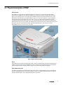
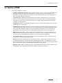
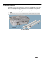
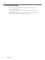
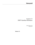
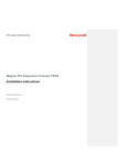
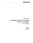
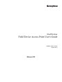
OneWireless
Field Device Access Point User's Guide
OWDOC-X256-en-220A
October 2013
Release 220
Document
Release
Issue
Date
OWDOC-X256-en-220A
220
0
October 2013
Disclaimer
This document contains Honeywell proprietary information. Information contained herein is to be used solely
for the purpose submitted, and no part of this document or its contents shall be reproduced, published, or
disclosed to a third party without the express permission of Honeywell International Sarl.
While this information is presented in good faith and believed to be accurate, Honeywell disclaims the implied
warranties of merchantability and fitness for a purpose and makes no express warranties except as may be stated
in its written agreement with and for its customer.
In no event is Honeywell liable to anyone for any direct, special, or consequential damages. The information
and specifications in this document are subject to change without notice.
Copyright 2013 - Honeywell International Sarl
2
www.honeywell.com
Contents
1 About this guide ..................................................................................................................................... 5
2 Introduction to FDAP ............................................................................................................................. 7
2.1
2.2
2.3
2.4
2.5
2.6
FDAP description ............................................................................................................................................... 8
Types of FDAPs ................................................................................................................................................ 10
Physical description of FDAP ........................................................................................................................... 11
Features of FDAP ............................................................................................................................................. 13
FDAP security .................................................................................................................................................. 14
FDAP technical specification and compliance information ............................................................................. 15
3 FDAP Installation .................................................................................................................................. 17
3.1
3.2
3.3
3.4
3.5
3.6
Prerequisites for installation ............................................................................................................................. 18
Inspect FDAP and associated hardware ........................................................................................................... 19
Identify FDAP site locations ............................................................................................................................ 20
Connect antennas .............................................................................................................................................. 21
Ground the FDAP ............................................................................................................................................. 23
Mount the FDAP .............................................................................................................................................. 24
3.6.1 Pole mounting .................................................................................................................................... 24
3.6.2 Wall or flat surface mounting ............................................................................................................ 25
3.7 Connect power cables and Ethernet cables ....................................................................................................... 26
3.7.1 DC power wiring ............................................................................................................................... 26
3.7.2 AC power wiring ............................................................................................................................... 27
3.7.3 Ethernet wiring .................................................................................................................................. 27
3.8 Power on and startup ........................................................................................................................................ 30
4 FDAP Configuration ............................................................................................................................. 31
4.1 Establish connection between WDM and FDAP .............................................................................................. 32
4.2 Provision an FDAP ........................................................................................................................................... 33
4.3 Description of FDAP parameters ...................................................................................................................... 34
5 FDAP Monitoring .................................................................................................................................. 41
5.1
5.2
5.3
5.4
5.5
Overview about monitoring ..............................................................................................................................
Verify connectivity using maps ........................................................................................................................
Monitor using Provisioning Device handheld ..................................................................................................
Monitor using events ........................................................................................................................................
Monitor using reports .......................................................................................................................................
42
43
44
45
46
6 FDAP Maintenance and Troubleshooting .......................................................................................... 47
6.1
6.2
6.3
6.4
Replace an FDAP .............................................................................................................................................
Remove an FDAP .............................................................................................................................................
Upgrade an FDAP firmware .............................................................................................................................
Troubleshoot an FDAP .....................................................................................................................................
48
49
50
51
7 Notices .................................................................................................................................................. 53
7.1 Documentation feedback .................................................................................................................................. 54
7.2 How to report a security vulnerability .............................................................................................................. 55
3
CONTENTS
4
www.honeywell.com
1 About this guide
This document describes the procedures to install, configure, and operate the Field Device Access Point
(FDAP). FDAP is one of the components in the OneWireless Network solution for industrial control.
Intended audience
This guide is intended for people who are responsible for planning, administering, and operating the
OneWireless Network. These people include Plant Managers, Process Engineers, and System Administrators.
Prerequisite skills
It is assumed that you are familiar with the operation of OneWireless Network, Experion system software, and
the plant processes which Experion controls, Microsoft Windows operating systems, and network
administration tasks.
How to use this guide
This guide provides guidance on:
•
•
•
•
•
FDAP description
FDAP installation
FDAP configuration
FDAP monitoring
FDAP maintenance and troubleshooting
Required Honeywell documentation
The following documents and sources contain additional information required for deploying OneWireless
Network. It is recommended to have these documents readily available for reference.
Document
Document ID
Description
OneWireless Network
Planning and Installation
Guide
OWDOC-X253-en-220A
This document provides
information about planning,
designing, and setting up the
OneWireless Network using
WDM, FDAPs, and field
devices.
OneWireless WDM User’s
Guide
OWDOC-X254-en-220A
This document describes the
procedures to provision,
configure, operate, and
monitor an ISA100 Wireless
wireless field device network
using Wireless Device
Manager (WDM).
5
1 ABOUT THIS GUIDE
Document
Document ID
Description
OneWireless Wireless LAN
Controller Configuration
Guide
OWDOC-X255-en-220A
This document provides
information about planning,
designing, setting up, and
configuring a OneWireless
Network using WDM,
FDAPs, Cisco 1552S APs,
and field devices.
FDAP Regulatory
Compliance Guide
—
This document describes the
FDAP Regulatory
Compliance information.
OneWireless Parameter
Reference Dictionary
OWDOC-X260-en-220A
This document provides
information about the
parameters associated with
OneWireless devices.
You can download Honeywell documentation from http://www.honeywellprocess.com web site.
6
www.honeywell.com
2 Introduction to FDAP
Related topics
“FDAP description” on page 8
“Types of FDAPs” on page 10
“Physical description of FDAP” on page 11
“Features of FDAP” on page 13
“FDAP security” on page 14
“FDAP technical specification and compliance information” on page 15
7
2 INTRODUCTION TO FDAP
2.1 FDAP description
The Field Device Access Point (FDAP) is a ruggedized industrial radio device intended for use in hazardous
location to provide wireless connectivity for ISA100 Wireless compatible field devices. As an industrial
meshing access point, FDAP provides secure and reliable wireless coverage for ISA100 Wireless field devices.
It also serves as a routing access point for ISA100 Wireless field devices and is located between the wired DCS
network and ISA100 Wireless-based wireless field devices. Once deployed in the field, FDAPs self-discover
and self-organize into a managed, secure, and redundant wireless field device mesh network. With FDAPs,
wireless field devices do not have to route data from other field devices. The following figure illustrates how
FDAPs are used in a OneWireless Network:
Figure 1: OneWireless Network
FDAP uses IEEE 802.15.4 standard based radio technology and combines spatial diversity with advanced error
correction schemes to communicate in a complex multi-path environment and in large communication areas. It
has an Ethernet interface for connection to the backbone network and an ISA100 Wireless compliant radio to
connect to the wireless field device network. It is a standalone, pole mountable, intrinsically-safe device,
suitable for use in hazardous locations. It is normally installed in the same area where industrial field devices
are installed. FDAP supports 10/100 Mbps Fast Ethernet and has spatial antenna diversity.
Table 1: FDAP models
8
Access Point type
Model numbers
Power options
Suitable for…
FDAP certified for Class I
Division 1, Zone 0/1 Areas
FDAP1
18 - 24VDC
Intrinsic Safety (IS) source for Class I
Division 1, Zone 0/1 applications
www.honeywell.com
2 INTRODUCTION TO FDAP
Access Point type
Model numbers
Power options
Suitable for…
FDAP certified for Class I
Division 2, Zone 2 Areas
FDAP2
120/230 VAC
Class I Division 2, Zone 2 and general
purpose applications
18 - 24VDC
9
2 INTRODUCTION TO FDAP
2.2 Types of FDAPs
Standalone FDAP
A standalone FDAP has a radio board and an autonomous power subsystem that operates within a range of
AC/DC inputs. Standalone FDAP supports ISA100 Wireless-based radio communication, and it does not
support Wi-Fi or other radio technologies. The standalone FDAP may be used for Class I Division 1, Zone 0/1
applications that require IS protection methods and design technique or Class I Division 2, Zone 2 and general
purpose applications.
FDAP as field router
A standalone FDAP can be used as a Field Router (FR). If FDAP is not connected to the physical Ethernet, it
functions as a line powered FR. FDAP as a line powered FR option can be used for extending field mesh into
hazardous environments where normal infrastructure nodes are not suitable.
10
www.honeywell.com
2 INTRODUCTION TO FDAP
2.3 Physical description of FDAP
FDAP enclosure
The FDAP has a rugged die-cast aluminum enclosure for outdoor use. The enclosure and all auxiliary
components are designed to meet IP66 and NEMA Type 4X ratings for protection against dust and water
ingress. The enclosure has two water-tight type N bulkhead connectors for antenna spatial diversity in the
FDAP radios. The half-inch rigid conduit hub has a gasket to seal out water and dust. A rigid conduit hub,
internal and external ground studs, and a removable cover are provided for field installation. Externally
accessible Infrared (IR) port allows the device to be commissioned in the field. Three status LEDs provide
information about power, device health, and communication. The enclosure may be mounted on a pole or on a
flat surface such as a wall using the available optional mounting brackets. The enclosure measures
approximately 20 cm x 13 cm x 7 cm (L x W x H).
Figure 2: Physical description of FDAP
IR port
The FDAP has an externally accessible IR port that is used for communicating with the Provisioning Device
handheld. The Provisioning Device handheld is used for commissioning the FDAP, reading, and setting the
various FDAP parameters. The IR port has a range of 20 cm and a beam width of 20 degrees.
FDAP communication radio
FDAP has ISA100 Wireless compliant radios that operate in the 2.4 GHz ISM band. It uses spatial antenna
diversity with sophisticated error correction schemes to improve communication and increase coverage in a
typical industrial complex where multi-path propagation is prevalent.
11
2 INTRODUCTION TO FDAP
Antennas
FDAP uses dual antenna diversity to improve communication reliability in severe multi-path environment. This
helps in improving radio coverage and provides robust communication links thereby reducing infrastructure cost
and cost per wireless field device.
FDAP has integral omni-directional antennas and it also supports a variety of high- and low-gain directional and
omni-directional antennas to provide flexibility in installation and to maximize performance of the wireless
system. For more information about certified antennas and the allowable maximum RF output power, refer to
the FDAP Regulatory Compliance Guide.
FDAP has integrated lightning suppressors on the antenna ports. The lightning suppressors are permanently
attached and do not require field maintenance. Lighting suppressors are required for all outdoor installations or
indoor installations where FDAP may be subjected to lightning surge. Optional remote mounted lightning
suppressors are available for use in application where the remote antenna cable is exposed to lightning surge.
LED indicators
FDAP has three LEDs for indicating the status and health of the device. For more information about LEDs,
refer to “Table 3: LED indicators”.
12
www.honeywell.com
2 INTRODUCTION TO FDAP
2.4 Features of FDAP
The features of FDAP are as follows:
•
24 VDC or 120/230 VAC powered: FDAP operates at 24 VDC or 120/230 VAC and provides better latency
than battery-based wireless field device mesh network. It enables the use of wireless field devices for
applications requiring fast update rates (less than 10 seconds) and short latency (less than 250 ms) and in
areas where Wi-Fi radios are not allowed.
•
Antenna diversity: FDAP uses spatial antenna diversity to improve communication success rates and to
improve coverage in multi-path environments. This is necessary for the majority of industrial application
where there is no direct line of site between field devices. Antenna diversity significantly improves data
availability in such applications.
•
Fast Ethernet: FDAP has 10/100 Mbps Fast Ethernet interface and can be integrated into any network that
supports Ethernet communication.
•
Field Mesh network: Multiple FDAPs can form a self-forming, self-healing wireless mesh network. This
extends the range and coverage of the wireless sensor network and provides redundant communication paths
for improved data availability. Unlike battery-power field devices, FDAPs are line powered and so can
aggregate data from multiple field devices including other FDAPs without concerns about battery life.
•
Reduced cost: FDAP reduces wireless field device cost, infrastructure cost, and cost per wireless I/O. It
reduces the number of ISA100 Wireless routing devices and offers wireless coverage for ISA100 Wireless
field devices. It has lesser installation cost than Access Points for sensor only applications.
•
Access points: FDAP acts as a routing access point for wireless field devices and it is designed for sensoronly network for monitoring application segment.
•
IPv6 device: FDAP is an Internet Protocol version 4 (IPv4) device. The IPv4 protocol provides an end-toend data transmission across multiple IP networks. FDAP gets the IP address from DHCP Server in Field
Device Network (FDN). You can ping an FDAP from the FDN network. You cannot ping an FDAP from the
Plant Control Network (PCN). You cannot ping an FDAP when used as a Router.
•
Backbone router: FDAP is a backbone router in a rugged industrial enclosure that acts as a bridge between
the field device network and wireless backhaul network such as IEEE 802.11 WLAN.
13
2 INTRODUCTION TO FDAP
2.5 FDAP security
OneWireless Network protects plant information and ensures safe operations with industry standard 128-bit
encryption at the mesh, Wi-Fi, and wireless field device level. The FDAP offers a robust embedded ISA100
Wireless security.
FDAP authentication
In addition to data encryption, ISA100 Wireless standard requires each FDAP to be authenticated before joining
the network. OneWireless Network relies on a more secured IR authentication key distribution method as it
requires users to be physically next to the FDAP to add it to the network. The authentication keys are generated
and managed by the WDM. A Provisioning Device handheld is used to upload the authentication keys from the
WDM to Provisioning Device handheld and to download keys to FDAPs using IR media. The IR media is used
to send an authentication key from the Provisioning Device handheld to the FDAP. Therefore, all Provisioning
Device handhelds and FDAPs have IR ports for device commissioning. The keys are encrypted when
distributed over the network. Once a key is deployed to an FDAP, it is validated by the WDM before the FDAP
can join the OneWireless Network. Key deployment is a one-time activity, that is, the devices can rejoin the
network after power down or after any other service interruptions without re-keying the device. OneWireless
supports a key rotation mechanism to enable a secure network. Once the devices join the network, a master key
and a session key is assigned to each device, and the session key can be rotated on a periodic basis. The key
rotation period can be configured from the OneWireless user interface. For best system performance, it is
recommended to set the key rotation period as infinite.
In addition, from OneWireless R210 release onwards, over the air provisioning is supported. This allows the
FDAPs to join the secure OneWireless Network and establish communication with other devices and the WDM.
Embedded ISA100 Wireless security
To reduce security threats, ISA100 Wireless requires all process data to be 128-bit encrypted. The data is
encrypted at the source and decrypted at the destination to provide end-to-end security for the process data. The
FDAPs self-discover other neighboring ISA100 Wireless routing devices, such as Access Points, and routing
ISA100 Wireless field devices, to form a reliable and secure ISA100 Wireless based wireless mesh network.
Wireless routing algorithm enables an FDAP to dynamically identify the best route to send data to and from
wireless field devices. This algorithm enables the field device mesh network to dynamically re-optimize itself
when FDAPs are added to or removed from the network.
14
www.honeywell.com
2 INTRODUCTION TO FDAP
2.6 FDAP technical specification and compliance information
For information about FDAP technical specification and regulatory compliance information, refer to the
OneWireless R200 Field Device Access Point Specifications document available at Honeywell Support Web
site.
15
2 INTRODUCTION TO FDAP
16
www.honeywell.com
3 FDAP Installation
Related topics
“Prerequisites for installation” on page 18
“Inspect FDAP and associated hardware” on page 19
“Identify FDAP site locations” on page 20
“Connect antennas” on page 21
“Ground the FDAP” on page 23
“Mount the FDAP” on page 24
“Connect power cables and Ethernet cables” on page 26
“Power on and startup” on page 30
17
3 FDAP INSTALLATION
3.1 Prerequisites for installation
Complete the network planning before installing FDAP. For information about network planning, refer to the
Network Planning and Installation Guide. Complete the following tasks before installing the FDAPs in the
wireless network.
•
Network site planning: Complete site planning to understand how a wireless network can be built and
supported for your application using OneWireless components.
•
RF site assessment: Perform an RF site assessment when designing a large wireless network. The site
assessment should at a minimum include the following tasks:
– Conduct the site assessment when the plant is operating, so that maximum possible interference can be
measured and addressed.
– Conduct RF spectrum analysis on the 2.40-2.49 GHz band to detect any potential RF interference. Strong
interference sources should be addressed (removed, avoided or minimized) before the installation. Note
that some frequencies may not be available for use in some locations and countries.
– Arrange point-to-point mesh in various locations to measure the RF propagation ability in the site.
Received Signal Strength Indicator (RSSI) can serve as an indicator of the RF environment. TCP/IP
throughput testing and UDP/IP throughput and packet drop rate testing should be conducted in all
selected locations to measure the quality of the signal strength in the site.
18
•
FDAP placement: Determine FDAP placement after the completion of the network planning and RF
assessment activities.
•
Power requirements: Identify power requirements for the network. Determine wired cable runs to provide
DC power to the FDAP.
•
Ethernet cable runs: Determine Ethernet cable runs for FDAP and/or any other wired nodes in the network.
www.honeywell.com
3 FDAP INSTALLATION
3.2 Inspect FDAP and associated hardware
Ensure that all the hardware that are necessary for completing the installation for each FDAP are available.
Examine whether the FDAP and the associated hardware like antennas and mounting brackets are damaged.
19
3 FDAP INSTALLATION
3.3 Identify FDAP site locations
The location of all FDAPs should be determined to ensure optimum operation in a wireless network. After the
completion of network site planning and RF assessment activities, the locations for FDAPs are identified.
Locations can be mapped so that the site preparation for FDAPs can be started. For more information about
prerequisites, refer to “Prerequisites for installation” on page 18.
20
www.honeywell.com
3 FDAP INSTALLATION
3.4 Connect antennas
Antennas play a critical role in the setup and operation of wireless mesh systems. Depending upon the results of
the site assessment and the requirements of the installed environment, proper antenna type (omni-directional
versus directional, low-gain versus high-gains, and so on) should be determined. The various types of antennas
offered with FDAP enhance the wireless coverage of the field devices in multi-path environment. It is
recommended to use same antenna type and gain on both antennas for optimum performance.
Attention
After the antennas are connected, the connections should be sealed to protect them from the external environment.
Figure 3: Antenna components
21
3 FDAP INSTALLATION
Figure 4: Antenna connections
22
www.honeywell.com
3 FDAP INSTALLATION
3.5 Ground the FDAP
The FDAP provides internal and external grounding point to meet various local and regulatory grounding
requirements. You should ensure that the FDAPs are grounded properly by a certified and authorized personnel,
and that it conforms to all applicable codes and regulations. The materials required to provide a proper ground
are defined by local regulations, and should be obtained locally to ensure that the correct safety environment is
achieved.
23
3 FDAP INSTALLATION
3.6 Mount the FDAP
The assembled FDAP, along with antennas and lightning suppressors (if required) can be mounted in its site
location. The FDAP enclosure can be mounted on a 2-inch pole or on a wall using the appropriate optional
mounting kit that is available with the unit.
3.6.1 Pole mounting
When pole mounting the FDAP, you can assemble and install the mounting hardware at the site. The mounting
kit includes the following items:
•
Mounting plate
•
U-bolts with nuts
•
Screws (to attach the FDAP to the mounting plate)
The pole mounting kit comprises of mounting plate, U-bolts, and nuts as displayed in “Figure 5: Pole
mounting ”. When using the mounting plate for the pole installation, secure the FDAP to the bracket using the
screws supplied with the bracket kit. The FDAP can be mounted to the left or to the right of the pole using the
same mounting hardware. It can also be mounted inline with the pole. However, if the integral antennas are too
close to the pole, it might cause RF communication problem. For inline mounting, the FDAP integral antennas
should be on the top of the mounting pole.
Figure 5: Pole mounting
24
www.honeywell.com
3 FDAP INSTALLATION
3.6.2 Wall or flat surface mounting
The wall mounting kit comprises a wall mounting plate and four screws as displayed in “Figure 6: Wall
mounting”. Both mounting plates fasten to four threaded bosses on the back of the FDAP. The FDAP should not
be mounted on metallic walls because the integral antennas are too close to the wall and causes RF propagation
problems.
Figure 6: Wall mounting
25
3 FDAP INSTALLATION
3.7 Connect power cables and Ethernet cables
FDAP has one Ethernet cable and one power cable. You have to construct conduit and cable runs for power and
Ethernet. The FDAP can be powered directly by universal AC power supply (90 – 240 VAC, 50/60 Hz) or by
external 24 VDC power supply such as distributed DC source. Ensure that all wires inside the enclosure are
routed and secured properly as displayed in“Figure 7: Ethernet and field DC power” and“Figure 8: Ethernet and
field AC power”. The FDAP has integrated terminal blocks that allow field wiring to be directly terminated
inside the FDAP without an additional external junction box. Power (both AC and DC) connection, Ethernet
and Serial connections can be terminated inside the FDAP.
3.7.1 DC power wiring
When powered from an external 24 VDC source, the power cable should be terminated directly onto the twoposition terminal block on the Power Board. The polarity of the connector is marked next to the connector on
the Power Board. The power cable should be shielded and the drain wire grounded inside the enclosure as
displayed in “Figure 7: Ethernet and field DC power”.
Secure all connections and wires and connect the cover-ground connection lug to the enclosure cover to
complete the wiring.
Figure 7: Ethernet and field DC power
Attention
For installations that require CE-mark compliance, the DC power source must be a CE-mark approved power supply.
In addition, the DC cable between the approved DC power source must be no more than 3.0 meters (9.8 feet) from the
FDAP.
26
www.honeywell.com
3 FDAP INSTALLATION
3.7.2 AC power wiring
When powered from an external AC source, the power cable should be terminated at the terminal block on the
AC/DC conversion module, marked as 24 VDC Power Brick as displayed in “Figure 8: Ethernet and field AC
power”.
•
•
•
•
To facilitate wiring, remove the Power Brick assembly from the enclosure by loosening the two retaining
screws and sliding the brick assembly out.
Terminate the AC cables at the AC terminal block on the Power Brick module. The module has polarity
markings for Live (L), Neutral (N) and Ground.
Ensure that all connections are secure and then slide the module back into the enclosure and secure it with
the retaining screws.
Secure all connections and wires and connect the cover-ground connection lug to the enclosure cover to
complete the wiring.
Attention
If an AC power option is ordered from the factory, the DC output of the power conversion module should be pre-wired
to the DC terminal block on the Power Board. Verify that the connection is secure and has the correct polarity as
marked.
Figure 8: Ethernet and field AC power
3.7.3 Ethernet wiring
FDAP has one Ethernet input for optional connection to a wired network or a wireless access point. If the FDAP
is connected to a wired Ethernet, you should run the Ethernet cabling from the control system through the
27
3 FDAP INSTALLATION
conduit to the FDAP site. You have to install the FDAP based on the Ethernet connection. If Ethernet cable is
connected, it acts as an FDAP (access point) and if the Ethernet cable connection is removed it acts as a line
powered FR (routing device). An 8-position Insulation Displacement Connector (IDC) terminal block allows
twisted pair Ethernet cable to be connected to the FDAP without stripping the wires or crimping on modular
RJ-45 plugs. The drain wire from the CAT5E cable shield should be connected to the internal grounding point
on the conduit hub. The cable should be solid core to ensure good signal quality and performance of up to 100
m.
Terminating the Ethernet cable
To terminate the Ethernet cable, perform the following steps.
1. Strip the outer jacket of the CAT5e cable and connect the shield drain wire to the internal grounding lug on
the conduit hub. Do not strip the individual twisted pair wires.
2. Connect the twisted pair wires to the IDC following the color chart marked next to the IDC. Note that the
color chart on the FDAP Power and I/O board assumes that the cable conforms to EIA/TIA 568B color code
which is the predominant color code for CAT5e cable. Refer to “Table 2: Ethernet IDC block pin-out” for
the necessary adjustment if the older EIA/TIA 568B color coded cable is used. Most of the CAT5E cables
conform to TIA/EIA 568B.
Table 2: Ethernet IDC block pin-out
PIN #
28
TIA/EIA 568A
TIA/EIA 568B
Data
1
Transmit+
2
Transmit-
3
Receive+
4
Unused
5
Unused
6
Receive-
7
Unused
8
Unused
www.honeywell.com
3 FDAP INSTALLATION
Testing Ethernet connection
A standard RJ-45 modular jack is available on the FDAP Power and IO board. The RJ-45 jack may be used to
test cable integrity after terminating the cable at the IDC connector. After terminating the field cable at the IDC,
connect the cable tester to the RJ-45 jack. An end-to-end cable test can then be performed to ensure proper
wiring at the IDC connector.
29
3 FDAP INSTALLATION
3.8 Power on and startup
The FDAP has status LEDs to indicate the various stages of operation.
Figure 9: LED indicators
The following table identifies the LEDs and describes the operating conditions of the unit when the LEDs are
turned ON.
Table 3: LED indicators
30
LED
Description
Power LED (Green)
Indicates that the power is supplied to FDAP. When the FDAP is
powered ON, Power LED turns ON automatically.
Status LED/Heart Beat LED (Green)
Indicates the software status of FDAP factory image. The Status LED
blinks ON/OFF once every second to indicate that the FDAP factory
firmware is in the working condition.
Comm LED (Green)
Indicates the Ethernet link activity.
www.honeywell.com
•
The LED is steady when there is a valid Ethernet link but no data
activity.
•
The LED blinks when there is data activity on the Ethernet link.
4 FDAP Configuration
Related topics
“Establish connection between WDM and FDAP” on page 32
“Provision an FDAP” on page 33
“Description of FDAP parameters” on page 34
31
4 FDAP CONFIGURATION
4.1 Establish connection between WDM and FDAP
To establish connection between WDMA and FDAP, power on the FDAP and connect FDAP to the WDM
through FDN port of WDM. If you are using multiple FDAPs, you can use an Ethernet switch to connect the
FDAPs to the WDM. WDM enables you to commission, configure, and monitor the FDAPs connected to it
from a centralized location. All FDAP configuration parameters are easily accessible from the WDM, which
centralizes all key functions required to manage the field device network and wireless field devices.
Log on to the OneWireless user interface and configure the WDM using the First Time Configuration Wizard.
The First Time Configuration wizard appears only for the first log on. For more information about First Time
Configuration and OneWireless user interface details, refer to the Wireless Device Manager User’s Guide.
32
www.honeywell.com
4 FDAP CONFIGURATION
4.2 Provision an FDAP
The FDAP should be given a unique authentication key to associate it with the wireless network in which it is
installed and operated. The authentication keys are generated and managed by the WDM. You can provision an
FDAP using over-the-air provisioning or using a Provisioning Device handheld. A Provisioning Device
handheld is used to upload the authentication keys from the WDM to the Provisioning Device handheld, and
then download the keys to FDAPs using IR media. You can send provisioning information (security, wireless)
from Provisioning Device handheld to the FDAP using IR communication link. Once the unit is set up and the
authentication is completed, the FDAP joins the network and starts communicating.
Attention
Before provisioning an FDAP, ensure that you have configured the WDM using the First Time Configuration Wizard
and the authentication keys are transferred to the Provisioning Device handheld from the WDM.
For more information about the procedure to provision an FDAP, refer to the Wireless Device Manager User’s
Guide.
33
4 FDAP CONFIGURATION
4.3 Description of FDAP parameters
Once the FDAP joins the network, you can configure and monitor the FDAP by using OneWireless user
interface. The Selection Panel in the OneWireless user interface provides a list of all the devices in the
OneWireless Network. The Property Panel in the OneWireless user interface provides configuration properties
of all the devices configured in the OneWireless Network. Select the required FDAP from the list of devices in
the Selection Panel, and then view the FDAP parameter details in the Property Panel.
Figure 10: FDAP Property Panel
The following table describes the FDAP parameter details.
Table 4: FDAP parameters in the selection panel
Panel
Group elements
Access Point Summary
Description
Tag Name: Displays the default device name.
You can rename the device. Device name can
be up to 16 alphanumeric characters long and
it should begin with an alphabet.
Status: Displays the device status as Joined
or Offline.
Default Map: You can select the required
map on which the device must be placed.
Description: Displays the entered description
for the device. You can type the required
description for the device.
Identification
34
www.honeywell.com
Displays the identification details like
Vendor, Model (device type), Serial Number
(EU ID of the device), Radio Revision
(firmware revision number) , Template Type,
and Template Revision..
4 FDAP CONFIGURATION
Panel
Group elements
Description
ISA100 Network Address
Displays the network address details like
IPv6 Address (128-bit network address),
EUI64 (unique ID), Short Address (16-bit
number assigned by system manager), and
the Routing Level.
Note: When you move the mouse pointer
over the partially visible data on the Property
Panel, the complete data is visible.
Device Management
ISA100 Time
Synchronization
Displays the tag name and the 16–bit address
of the time master of the device, and the time
distribution level.
Power
Displays the power supply status as Line
Powered (for access points) or Battery
Powered (for routing devices). By default,
power status is always Line Powered for
FDAP.
Routing Assignment
Displays the routing configuration of the
device. The different types of configuration
are Non-Routing Device, Routing Device,
and Not Applicable. By default, Routing
Assignment is not applicable for FDAP and it
should not be changed.
Role Capability
Displays the capable roles of a device. By
default, FDAP can be an access point device,
if you enable over-the-air provisioning then it
can act as a provisioning device.
The different roles that can be configured are
Provisioning Device handheld, System Time
Source, Security Manager, System Manager,
Gateway, Access Point, Routing Device, and
I/O Device. If the Ethernet is plugged, it acts
as an access point and if the Ethernet is
unplugged, it acts as a routing device.
Assigned Role
Displays the current assigned role of the
device.
Command
Consists of the Join Command parameter
which is used to restart a device or to reset a
device to factory default state. Join
Command parameter has the following
options:
•
•
•
None
Warm Restart: To restart a device.
Warm Restart preserves static and
constant attributes data.
Restart as Provisioned: To reset the
device to factory default state. Restart as
Provisioned corresponds to the
provisioned state of the device in which
the device only retains the data received
during its provisioning.
35
4 FDAP CONFIGURATION
Panel
Group elements
Description
Uptime and Connectivity
Displays the uptime and connectivity details,
which are as follows:
•
•
•
•
Uptime: Time (in seconds) during which
the device is online.
Restart Count: Number of times the
device is restarted. The Restart Count
begins from one when it is reset to
default.
Device Drop Off Count: Number of
times the device is disconnected from the
network.
Reset Statistics: Resets only the Device
Drop-off Count. Click to reset the Device
Drop Off Count.
Attention
When a device is reset to default
through a Provisioning Device
handheld, the Restart Count and Device
Drop-off Count are reset to 0.
Communication
Redundancy
Displays the Communication Redundancy
State, Communication Redundancy Ratio
details.
The Communication Redundancy State is
the redundancy communication link between
the primary and secondary parent.
Select the Comm Redun Alarm check box
to enable the "Non-Redundant
Communication" alarm for this FDAP.
Attention
This alarm is applicable only when the
FDAP is acting as an FDAP router.
Diagnostics
Displays the ISA100 Wireless radio
diagnostics details.
Network Time Protocol
Displays the Time Master Preferred, Round
Trip Time, Time Sync Drift details.
Time Master Preferred: Time Master
preferred is set if the Node/Device is NTP
Sync capable or incapable.
Time Sync Drift: Time Sync Drift is the time
drift of the Node/Device from its Parent in
clock ticks.
Round trip time: The duration of the
response of the Ping from system manager.
Over-The-Air provisioning
36
www.honeywell.com
Consists of the over-the-air provisioning
parameters for enabling and disabling overthe-air provisioning. It also displays the time
remaining for over-the-air provisioning.
4 FDAP CONFIGURATION
Panel
Group elements
Description
Data Layer Management
Radio Power Level
Displays the transmission power level. The
default power level is 16 dBm.
Neighbor Diagnostics
Displays the neighboring devices diagnostics
like the Device Tag Name, RSSI, RSQI,
Transmit Fail, Transmit CCA Backoff,
Transmit NACK, and Clock Sigma.
Channel Diagnostics
Displays the device’s channel diagnostics like
channel, No ACK, and CCA Backoff.
37
4 FDAP CONFIGURATION
Panel
Description
Displays the details about the ISA100
Wireless data link layer statistics for a
selected device. Displays the Read Message
Totals, Write Message Totals, and Execute
Message Totals details.
Radio Disconnect History
Displays the radio disconnect history details.
Radio Diversity
38
Group elements
Statistics (DMAP)
www.honeywell.com
Error Distribution Count
Displays the error distribution counter, which
corresponds to the error packet counter for
the number of bytes corrected. The error
packet counter is the total count of error
packets received on both antennas with
Cyclic Redundancy Check (CRC) error.
4 FDAP CONFIGURATION
Panel
Group elements
Description
Statistics
Diversity Operation: Displays the FDAP
antenna operational status. The status can be
Both Radios, Radio 1, or Radio 2.
Correction Gain: Displays the correction
gain, which is the total packet corrected by
packet error correction algorithm.
Redundancy Gain: Displays the redundancy
gain, which is the minimum value of total
packets received by antenna 1 without any
packet errors + minimum value of total
packets received by antenna 2 without any
packet errors / total packets received by
antenna 1 and 2 without any packet errors.
Reset Statistics: Resets all the radio diversity
values. Click to reset all the radio diversity
values.
Notes
Displays notes entered for the FDAP. You can
type notes regarding the FDAP.
39
4 FDAP CONFIGURATION
40
www.honeywell.com
5 FDAP Monitoring
Related topics
“Overview about monitoring” on page 42
“Verify connectivity using maps” on page 43
“Monitor using Provisioning Device handheld” on page 44
“Monitor using events” on page 45
“Monitor using reports” on page 46
41
5 FDAP MONITORING
5.1 Overview about monitoring
The status and performance of FDAPs operating in a wireless network can be monitored in a number of ways.
•
•
•
42
The Monitoring tab in the OneWireless user interface enables you to monitor FDAPs that are commissioned
in the network.
The Alarms & Event tab in the OneWireless user interface enables you to monitor events generated by the
FDAPs.
The Reports tab in the OneWireless user interface enables you to view and generate custom reports about
connectivity and device health of the FDAPs in a network.
www.honeywell.com
5 FDAP MONITORING
5.2 Verify connectivity using maps
The OneWireless user interface enables you to create multiple locations and upload site map to the location.
You can position the devices on the map to reflect the physical design and structure of your plant. You can
visually inspect network topology map and connectivity. You can navigate to the device in the topology map
and check the link signal quality and connectivity. In addition, you can examine device communication statistics
information like Receive Signal Quality Index (RSQI) and Receive Signal Strength Index (RSSI). This helps the
network services engineer to verify the ISA100 Wireless mesh connectivity and FDAP connectivity in the
OneWireless user interface.
Figure 11: Map view
For more information about setting up a monitoring area and for location specific monitoring, refer to the
Wireless Device Manager User’s Guide.
43
5 FDAP MONITORING
5.3 Monitor using Provisioning Device handheld
FDAP is authenticated using a Provisioning Device handheld. Once the FDAP is authenticated, it joins the
network. Provisioning Device handheld can be used to monitor the status of the authenticated FDAP and
Provisioning Device handheld displays status as Discover, Secure, Joined, or Not Joined. You can read and set
various FDAP parameters through the Provisioning Device handheld. If the FDAP is not joining the network,
you can read the FDAP parameter data through the Provisioning Device handheld and troubleshoot.
44
www.honeywell.com
5 FDAP MONITORING
5.4 Monitor using events
You can monitor system events generated by the FDAP. Events are generated when the FDAP joins the network,
when the FDAP is Online, or when the FDAP is Offline or switched off. You can also export the event log
created for a particular time period. For more information about monitoring device using events, refer to the
Wireless Device Manager User’s Guide.
45
5 FDAP MONITORING
5.5 Monitor using reports
You can generate and view various reports about connectivity, and device health of FDAPs in a network. You
can generate and view the following reports:
•
•
•
•
•
Device health overview
Device summary
Device history
Connection summary
Connection history
You can print the report and save the report in .csv format. For more information about reports, refer to the
Wireless Device Manager User’s Guide.
46
www.honeywell.com
6 FDAP Maintenance and Troubleshooting
Related topics
“Replace an FDAP” on page 48
“Remove an FDAP” on page 49
“Upgrade an FDAP firmware” on page 50
“Troubleshoot an FDAP” on page 51
47
6 FDAP MAINTENANCE AND TROUBLESHOOTING
6.1 Replace an FDAP
You can replace a failed FDAP with a new device only if the new device specification is identical to the failed
one. For more information about the procedure to replace an FDAP, refer to the Wireless Device Manager
User’s Guide.
Figure 12: Maintenance icons
Attention
Any maintenance required is limited only to the external enclosure surface, cable connections, antennas, and the
firmware. A failed unit should be returned to Honeywell for maintenance, repair, or replacement.
48
www.honeywell.com
6 FDAP MAINTENANCE AND TROUBLESHOOTING
6.2 Remove an FDAP
You can remove a failed FDAP from the network. Once the FDAP is removed it will not be able to join the
network until it is assigned a new provisioning key. For more information about the procedure to remove an
FDAP, refer to the Wireless Device Manager User’s Guide.
49
6 FDAP MAINTENANCE AND TROUBLESHOOTING
6.3 Upgrade an FDAP firmware
FDAPs have only radio firmware and the radio firmware can be upgraded over-the-air. For more information
about the procedure to upgrade a firmware for FDAP, refer to the Wireless Device Manager User’s Guide.
50
www.honeywell.com
6 FDAP MAINTENANCE AND TROUBLESHOOTING
6.4 Troubleshoot an FDAP
FDAP does not have any user-serviceable parts inside the FDAP enclosure; any failure within the FDAP
requires a hardware replacement. If a fault or a failure is indicated or suspected in an FDAP in the network,
there are many ways to diagnose a problem. You can diagnose a problem using the following methods:
•
Diagnose using events
•
Diagnose using reports
•
Diagnose using system logs
•
Diagnose using Provisioning Device handheld
System logs
The system log contains events logged in the system. The system log information is helpful to System
Administrators, Field Engineers, and technical support personnel. You can generate and view the system log
details. You can save the system log details in tar.gz format. For more information about system logs, refer to
the Wireless Device Manager User’s Guide.
Recovering from failures
Failure indication may be signaled through the FDAP status LEDs. You can restart the FDAP if a failure is
suspected. For more information about the procedure to restart the FDAP, refer to the Wireless Device Manager
User’s Guide.
51
6 FDAP MAINTENANCE AND TROUBLESHOOTING
52
www.honeywell.com
7 Notices
Other trademarks
Microsoft and SQL Server are either registered trademarks or trademarks of Microsoft Corporation in the
United States and/or other countries.
Trademarks that appear in this document are used only to the benefit of the trademark owner, with no intention
of trademark infringement.
Third-party licenses
This product may contain or be derived from materials, including software, of third parties. The third party
materials may be subject to licenses, notices, restrictions and obligations imposed by the licensor. The licenses,
notices, restrictions and obligations, if any, may be found in the materials accompanying the product, in the
documents or files accompanying such third party materials, in a file named third_party_licenses on the media
containing the product, or at http://www.honeywell.com/ps/thirdpartylicenses.
53
7 NOTICES
7.1 Documentation feedback
You can find the most up-to-date documents on the Honeywell Process Solutions website at:
http://www.honeywellprocess.com/
If you have comments about Honeywell Process Solutions documentation, send your feedback to:
[email protected]
Use this email address to provide feedback, or to report errors and omissions in the documentation. For
immediate help with a technical problem, contact your local support center.
54
www.honeywell.com
7 NOTICES
7.2 How to report a security vulnerability
For the purpose of submission, a security vulnerability is defined as a software defect or weakness that can be
exploited to reduce the operational or security capabilities of the software.
Honeywell investigates all reports of security vulnerabilities affecting Honeywell products and services.
To report a potential security vulnerability against any Honeywell product, please follow the instructions at:
https://honeywell.com/pages/vulnerabilityreporting.aspx
Submit the requested information to Honeywell using one of the following methods:
•
Send an email to [email protected].
•
or
Contact your local Honeywell Technical Assistance Center (TAC) or support center listed in the “Support
and other contacts” section of this document.
55
7 NOTICES
56
www.honeywell.com