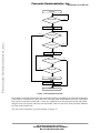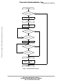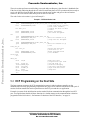
1
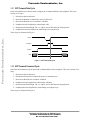
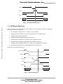
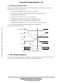
Freescale Semiconductor, Inc...
Freescale Semiconductor
ECP Standard Parallel Interface for
DSP56300 Devices
Application Note
by
Mihai V. Micea
Dan Chiciudean
and Lucian Muntean
AN2085/D
Rev. 0, 11/2000
© Freescale Semiconductor, Inc., 2004. All rights reserved.
For More Information On This Product,
Go to: www.freescale.com
Freescale Semiconductor, Inc.
How to Reach Us:
Home Page:
www.freescale.com
Freescale Semiconductor, Inc...
E-mail:
[email protected]
USA/Europe or Locations Not Listed:
Freescale Semiconductor
Technical Information Center, CH370
1300 N. Alma School Road
Chandler, Arizona 85224
+1-800-521-6274 or +1-480-768-2130
[email protected]
Europe, Middle East, and Africa:
Freescale Halbleiter Deutschland GmbH
Technical Information Center
Schatzbogen 7
81829 Muenchen, Germany
+44 1296 380 456 (English)
+46 8 52200080 (English)
+49 89 92103 559 (German)
+33 1 69 35 48 48 (French)
[email protected]
Japan:
Freescale Semiconductor Japan Ltd.
Headquarters
ARCO Tower 15F
1-8-1, Shimo-Meguro, Meguro-ku,
Tokyo 153-0064
Japan
0120 191014 or +81 3 5437 9125
[email protected]
Asia/Pacific:
Freescale Semiconductor Hong Kong Ltd.
Technical Information Center
2 Dai King Street
Tai Po Industrial Estate
Tai Po, N.T., Hong Kong
+800 2666 8080
[email protected]
For Literature Requests Only:
Freescale Semiconductor Literature Distribution Center
P.O. Box 5405
Denver, Colorado 80217
1-800-441-2447 or 303-675-2140
Fax: 303-675-2150
[email protected]
Information in this document is provided solely to enable system and software
implementers to use Freescale Semiconductor products. There are no express or
implied copyright licenses granted hereunder to design or fabricate any integrated
circuits or integrated circuits based on the information in this document.
Freescale Semiconductor reserves the right to make changes without further notice to
any products herein. Freescale Semiconductor makes no warranty, representation or
guarantee regarding the suitability of its products for any particular purpose, nor does
Freescale Semiconductor assume any liability arising out of the application or use of
any product or circuit, and specifically disclaims any and all liability, including without
limitation consequential or incidental damages. “Typical” parameters which may be
provided in Freescale Semiconductor data sheets and/or specifications can and do
vary in different applications and actual performance may vary over time. All operating
parameters, including “Typicals” must be validated for each customer application by
customer’s technical experts. Freescale Semiconductor does not convey any license
under its patent rights nor the rights of others. Freescale Semiconductor products are
not designed, intended, or authorized for use as components in systems intended for
surgical implant into the body, or other applications intended to support or sustain life,
or for any other application in which the failure of the Freescale Semiconductor product
could create a situation where personal injury or death may occur. Should Buyer
purchase or use Freescale Semiconductor products for any such unintended or
unauthorized application, Buyer shall indemnify and hold Freescale Semiconductor
and its officers, employees, subsidiaries, affiliates, and distributors harmless against all
claims, costs, damages, and expenses, and reasonable attorney fees arising out of,
directly or indirectly, any claim of personal injury or death associated with such
unintended or unauthorized use, even if such claim alleges that Freescale
Semiconductor was negligent regarding the design or manufacture of the part.
For More Information On This Product,
Go to: www.freescale.com
Freescale Semiconductor, Inc.
Abstract and Contents
The data communication between the DSP and a host computer is one of the important issues in designing
DSP-based systems directly connected to PCs which are commonly used as process controllers or as
interactive user interfaces. This application note proposes the implementation of a high-performance, yet
relatively simple, parallel data communication protocol for a DSP connected to a PC.
Freescale Semiconductor, Inc...
This document focuses on the implementation of the Extended Capabilities Port (ECP) parallel
communication standard on the DSP56300 family processors.
Specific ECP communication protocols are described along with the characteristic hardware and software
implementation details, both on the DSP and on the PC side. The performance evaluation routines
designed for the ECP data link are also presented, along with the corresponding results and conclusions.
1
Introduction . . . . . . . . . . . . . . . . . . . . . . . . . . . . . . . . . . . . . . . . . . . . . . . . . . . . . 1
2
DSP-Host Communication Tradeoffs . . . . . . . . . . . . . . . . . . . . . . . . . . . . . . 1
3
ECP Standard Specifications . . . . . . . . . . . . . . . . . . . . . . . . . . . . . . . . . . . . . . 2
3.1
3.2
3.2.1
3.2.2
3.2.3
3.2.4
3.3
ECP Hardware Description. . . . . . . . . . . . . . . . . . . . . . . . . . . . . . . . . . . . . . . . . . . .
ECP Handshaking Protocols . . . . . . . . . . . . . . . . . . . . . . . . . . . . . . . . . . . . . . . . . . .
ECP Forward Data Cycle . . . . . . . . . . . . . . . . . . . . . . . . . . . . . . . . . . . . . . . . . .
ECP Forward Command Cycle. . . . . . . . . . . . . . . . . . . . . . . . . . . . . . . . . . . . . .
ECP Reverse Data Cycle . . . . . . . . . . . . . . . . . . . . . . . . . . . . . . . . . . . . . . . . . .
ECP Reverse Command Cycle . . . . . . . . . . . . . . . . . . . . . . . . . . . . . . . . . . . . . .
ECP Software Registers . . . . . . . . . . . . . . . . . . . . . . . . . . . . . . . . . . . . . . . . . . . . . .
4
ECP Interface Implementation—Hardware . . . . . . . . . . . . . . . . . . . . . . . . . . 8
5
ECP Interface Implementation—Software . . . . . . . . . . . . . . . . . . . . . . . . . . 9
5.1
5.1.1
5.1.2
5.1.3
5.2
Implementation on the DSP Side . . . . . . . . . . . . . . . . . . . . . . . . . . . . . . . . . . . . . . . 9
Initialization . . . . . . . . . . . . . . . . . . . . . . . . . . . . . . . . . . . . . . . . . . . . . . . . . . . . 9
Forward Data . . . . . . . . . . . . . . . . . . . . . . . . . . . . . . . . . . . . . . . . . . . . . . . . . . 10
Reverse Data . . . . . . . . . . . . . . . . . . . . . . . . . . . . . . . . . . . . . . . . . . . . . . . . . . . 12
ECP Programming on the Host Side. . . . . . . . . . . . . . . . . . . . . . . . . . . . . . . . . . . . 14
6
Performance Evaluation of the ECP Interface . . . . . . . . . . . . . . . . . . . . . . 16
6.1
6.2
Single-Byte Transmission. . . . . . . . . . . . . . . . . . . . . . . . . . . . . . . . . . . . . . . . . . . . 16
Buffered Transmission . . . . . . . . . . . . . . . . . . . . . . . . . . . . . . . . . . . . . . . . . . . . . . 17
7
Boosting Performance with a DMA Controller . . . . . . . . . . . . . . . . . . . . . 18
Abstract and Contents
For More Information On This Product,
Go to: www.freescale.com
2
3
4
4
5
6
6
Freescale Semiconductor, Inc.
Conclusion . . . . . . . . . . . . . . . . . . . . . . . . . . . . . . . . . . . . . . . . . . . . . . . . . . . . . 20
9
About the Authors . . . . . . . . . . . . . . . . . . . . . . . . . . . . . . . . . . . . . . . . . . . . . . 21
10
References . . . . . . . . . . . . . . . . . . . . . . . . . . . . . . . . . . . . . . . . . . . . . . . . . . . . . 21
Freescale Semiconductor, Inc...
8
ECP Standard Parallel Interface for DSP56300 Devices
For More Information On This Product,
Go to: www.freescale.com
Freescale Semiconductor, Inc.
1
Introduction
Freescale Semiconductor, Inc...
An important set of real-life digital signal processing applications involves a host computer functioning as
a system controller or interactive graphical user interface. In these applications, reliable, high-speed data
communication between the DSP and the host computer is an important design and implementation issue.
This document describes the implementation of a high-performance, yet relatively simple, parallel data
communication protocol for a DSP connected to a PC. The paper focuses on the implementation of the
Extended Capabilities Port (ECP) parallel communication standard on the DSP56300 family processors.
Specific ECP communication protocols are described, as well as hardware and software implementation
details for both the DSP and the PC. Performance evaluation routines designed for the ECP data link are
also presented, along with corresponding results and conclusions.
Details of the ECP standard can be found in the Microsoft document, Extended Capabilities Port:
Specifications, Revision 1.06.
2
DSP-Host Communication Tradeoffs
The DSP56300 family features various data communication interfaces, suitable for a large variety of
system interconnections, through its built-in peripheral ports.
The Serial Communication Interface (SCI) provides a full-duplex port for serial data transfers. Using three
dedicated signals (Data Transmit, Data Receive, and Serial Clock), this interface supports industrystandard asynchronous bit rates and protocols up to 115200 bps, as well as high-speed synchronous data
transmission up to 8.25 Mbps for a 66 MHz clock. The primary disadvantage of a SCI-based connection
with a host computer is that the maximum data transfer rate is limited to 115200 bps by the computer’s
serial interface. Another disadvantage is that many DSP-based evaluation modules use the DSP serial port
for code development and debugging, making it difficult to develop a DSP program that can initiate serial
data transactions autonomously with a host computer.
For high-performance parallel data transfers, the DSP56300 family provides a full-duplex, double-buffered
parallel port called the Host Interface. This interface is either 8-bits or 32-bits wide, depending on the
particular DSP device selected. The HI08 or HI32 can connect directly to the data bus of a host processor
or computer with minimal glue logic, allowing direct data links to microcontrollers such as the Freescale
HC11 or the Intel 8051 family, as well as to microprocessors such as the Freescale 68k family or Intel x86
family. The Host Interface can easily connect with the high-speed ISA or PCI bus on a PC to form a
communication channel that is substantially faster than a serial connection (up to 16 MBps for the ISA bus,
for example). However, this solution requires a very close physical connection, which drastically reduces
overall system flexibility.
A good compromise between maximum data transfer speed and system flexibility is the parallel cable
interconnection. The standard PC protocol for high-performance parallel communication is the Extended
Capabilities Port (ECP). This document describes the hardware and software implementation of the ECP
Standard with the HI08 port of a DSP56300 family device.
Introduction
For More Information On This Product,
Go to: www.freescale.com
Freescale Semiconductor, Inc.
3
ECP Standard Specifications
The Extended Capabilities Port is a fast, bidirectional parallel interface developed by Microsoft and
Hewlett-Packard. It is backward-compatible with the existing PC standard parallel port (SPP)
configurations, using the existing parallel connectors and cables.
Pre-existing parallel communication methods utilized a wide variety of hardware and software interfaces,
each with unique and incompatible signaling schemes. The ECP standard was developed to provide a
standard, open path for communications between computers and more intelligent printers and peripherals.
The availability of this standard bidirectional protocol encourages the development of new peripherals that
can return both data and status to the host computer.
Freescale Semiconductor, Inc...
The ECP protocol generates handshake signals identical to those of the Extended Parallel Port (EPP), and
runs at the same speed as EPP. It also supports Run Length Encoding (RLE) to achieve data compression
ratios up to 64:1.
In summary, the ECP provides the following features:
•
High performance half-duplex forward and reverse channel
•
Interlocked handshake for fast, reliable data transfer
•
Optional single-byte RLE compression for improved throughput
•
Channel addressing for low-cost peripherals
•
Active output drivers
•
Adaptive signal timing
•
Peer-to-peer capability
The ECP provides three operational modes for compatibility with various systems:
•
Compatible mode—asynchronous, byte-wide forward channel (host-to-peripheral), parallel port
interface. Data and status lines are used according to the original SPP and EPP definitions.
•
Nibble mode—asynchronous, byte-wide reverse channel (peripheral-to-host), parallel port
compatible with all existing PC hosts. Data bytes are transmitted as two sequential 4-bit nibbles
using four peripheral-to-host status lines.
•
Byte mode—asynchronous, byte-wide reverse channel using the eight data lines of the interface for
data and the control/status lines for handshaking, compatible with IBM PS/2 hosts.
In addition, the ECP offers:
•
ECP mode—fast bidirectional channel, with or without RLE compression. This mode requires
custom hardware.
3.1 ECP Hardware Description
The Extended Capabilities Port uses the industry-standard DB25 connector and is backward-compatible
with the SPP and EPP parallel standards. When the ECP operates in SPP or EPP mode, the data and
handshake lines operate according to the SPP and EPP definitions.
When the port operates in ECP mode, each of the DB25 connector pins has a unique function, as listed in
Table 1.
ECP Standard Parallel Interface for DSP56300 Devices
For More Information On This Product,
Go to: www.freescale.com
Freescale Semiconductor, Inc.ECP Handshaking Protocols
Table 1. Pin Assignments for Extended Capabilities Parallel Port Connector
Pin
Freescale Semiconductor, Inc...
1
SPP Signal
ECP Signal
Input/
Output
Function
Strobe
HostCLK
Output
2–9
Data 0–7
Data 0–7
I/O
10
Ack
PeriphCLK
Input
A low on this line indicates valid data at the peripheral. When
this pin is deasserted, the +ve clock edge should be used to
shift the data into the host.
11
Busy
PeriphAck
Input
In reverse channel operation, a high on this pin indicates a
data cycle, while a low indicates a command cycle. In forward
channel operation, the pin functions as PeriphAck.
12
Paper Out / End
nAckReverse
Input
The peripheral pulls this pin low to acknowledge a reverse
request.
13
Select
X-Flag
Input
Extensibility Flag
14
Auto Linefeed
Host Ack
15
Error / Fault
PeriphRequest
16
Initialize
nReverseRequest
Output
This pin is pulled low to indicate that data is in the reverse
direction.
17
Select Printer
1284 Active
Output
The host pulls this pin high to indicate 1284 transfer mode, and
pulls the pin low to terminate.
Ground
Ground
18–25
A low on this line indicates valid data at the host. When this pin
is de-asserted, the +ve clock edge should be used to shift the
data into the peripheral.
Bidirectional data bus
Output
In forward channel operation, a high on this pin indicates a
data cycle, while a low indicates a command cycle. In reverse
channel operation, the pin functions as HostAck.
Input
The peripheral pulls this pin low to indicate that reverse data is
available.
GND
Ground
3.2 ECP Handshaking Protocols
The ECP can be fully implemented by hardware with custom parallel communication controllers. It can be
implemented in software as well.
The ECP handshaking protocol features the following four cycles:
•
Forward Data
•
Reverse Data
•
Forward Command
•
Reverse Command
ECP Standard Specifications
For More Information On This Product,
Go to: www.freescale.com
Freescale Semiconductor, Inc.
3.2.1 ECP Forward Data Cycle
In the forward data cycle, the host sends a single byte of compressed data to the peripheral. This cycle
consists of six steps:
1. Host places data on data lines.
2. Host asserts HostAck to indicate the start of a data cycle.
3. Host asserts HostClk to low to indicate valid data.
4. Peripheral asserts PeriphAck to acknowledge valid.
5. Host deasserts HostClk high. The +ve edge is used to shift data into the peripheral.
6. Peripheral de-asserts PeriphAck to acknowledge receiving the byte.
Freescale Semiconductor, Inc...
These steps are illustrated in Figure 1.
HostClk
PeriphAck
HostAck
Data
Figure 1. ECP Forward Data Cycle
3.2.2 ECP Forward Command Cycle
In the forward command cycle, the host sends a channel address to the peripheral. This cycle consists of six
steps:
1. Host places data on data lines.
2. Host deasserts HostAck to indicate the start of a command cycle.
3. Host asserts HostClk low to indicate valid data.
4. Peripheral asserts PeriphAck to acknowledge valid data.
5. Host deasserts HostClk high. The +ve edge is used to shift data into the peripheral.
6. Peripheral deasserts PeriphAck to acknowledge receiving the byte.
These steps are illustrated in Figure 2.
ECP Standard Parallel Interface for DSP56300 Devices
For More Information On This Product,
Go to: www.freescale.com
Freescale Semiconductor, Inc.ECP Handshaking Protocols
HostClk
PeriphAck
HostAck
Data
Freescale Semiconductor, Inc...
Figure 2. ECP Forward Command Cycle
3.2.3 ECP Reverse Data Cycle
In the reverse data cycle, the peripheral sends a single byte of data to the host. There are eight steps
specified for the reverse data cycle:
1. Host sets nReverseRequest Low to request a reverse channel.
2. Peripheral asserts nAckReverse low to acknowledge reverse channel request.
3. Peripheral places data on data lines.
4. Peripheral pulls PeriphAck high to select data cycle.
5. Peripheral pulls PeriphClk low to indicate that valid data is present.
6. Host pulls HostAck high to acknowledge that valid data is present.
7. Peripheral pulls PeriphClk high. The +ve edge is used to shift data into the host.
8. Host deasserts HostAck low to acknowledgment receipt of the byte.
These steps are illustrated in Figure 3.
nReverse Request
nAckReverse
PeriphClk
HostAck
PeriphAck
Data
Figure 3. ECP Reverse Data Cycle
ECP Standard Specifications
For More Information On This Product,
Go to: www.freescale.com
Freescale Semiconductor, Inc.
3.2.4 ECP Reverse Command Cycle
In the reverse command cycle, the peripheral sends a channel address to the host. There are eight steps
specified for the reverse command cycle:
1. Host sets nReverseRequest Low to request a reverse channel.
2. Peripheral asserts nAckReverse low to acknowledge reverse channel request.
3. Peripheral places data on data lines.
4. Peripheral pulls PeriphAck low to select command cycle.
5. Peripheral pulls PeriphClk low to indicate that valid data is present.
6. Host pulls HostAck high to acknowledge that valid data is present.
7. Peripheral pulls PeriphClk high. The +ve edge is used to shift data into the host.
Freescale Semiconductor, Inc...
8. Host deasserts HostAck low to acknowledgment receipt of the byte.
These steps are illustrated in Figure 4.
nReverse Request
nAckReverse
PeriphClk
HostAck
PeriphAck
Data
Figure 4. ECP Reverse Command Cycle
3.3 ECP Software Registers
The software registers implemented in a standard PC on the host side of the ECP interface are listed in
Table 2. The first 3 registers are identical to those in the Standard Parallel Port.
ECP Standard Parallel Interface for DSP56300 Devices
For More Information On This Product,
Go to: www.freescale.com
Freescale Semiconductor, Inc.
ECP Software Registers
Table 2. ECP Registers
Address
Freescale Semiconductor, Inc...
Base + 0
Port Name
Read/Write
Description
Data (SPP)
Read/Write
Standard parallel port data register. Writing to this
register in SPP mode drives data on the parallel port
data lines. In all other modes the drivers can be
tri-stated by setting the direction bit in the Control
Register.
ECP Address FIFO (ECP mode)
Read/Write
Data written to this address is placed in the FIFO and
tagged as ECP Address/RLE. ECP port hardware
transmits the byte to the peripheral automatically.
Base + 1
Status Register
Read
Reflects the inputs on the parallel port interface.
Base + 2
Control Register
Read/Write
Directly controls several output signals, sets the direction of communication, and enables an interrupt on
the rising edge.
Base + 400h
Data FIFO (Parallel Port FIFO Mode)
Read/Write
In Parallel Port FIFO Mode, any data written to the
Data FIFO is sent to the peripheral using the SPP
handshake; hardware generates the handshaking
required.
Data FIFO (ECP Mode)
Read/Write
When data direction is 0 (output to peripheral), bytes
written or DMAed from the system to this FIFO are
transmitted to the peripheral by hardware handshake
using the ECP parallel port protocol. When data direction is 1 (input from peripheral), bytes from the peripheral are read into this FIFO under automatic hardware
handshake from ECP.
Test FIFO (Test Mode)
Read/Write
Data can be read, written, or DMAed to or from the
system to this FIFO in any direction; data is not transmitted to the parallel port lines using a hardware protocol handshake but can be displayed on the parallel
port data lines.
Configuration Register A (Configuration Mode)
Read/Write
Indicates if the card generates level- or edge-triggered interrupts and the bus widths within the card,
and determines if there are any bytes left in the FIFO.
Configuration Register A is accessible only when the
ECP Port is in Configuration Mode.
Base + 401h
Configuration Register B (Configuration Mode)
Read/Write
Selects compression option (RLE) for outgoing data,
returns the status of the IRQ pin, IRQ assignment and
DMA Channel assignment. Configuration Register B
is accessible only when the ECP Port is in Configuration Mode.
Base + 402h
Extended Control Register
Read/Write
Configures the ECP mode and returns the status of
the ECP FIFO. Modes of operation include:
• Standard Mode
• Byte / PS/2 Mode
• Parallel Port FIFO Mode
• ECP FIFO Mode
• EPP Mode
• FIFO Test Mode
• Configuration Mode
ECP Standard Specifications
For More Information On This Product,
Go to: www.freescale.com
Freescale Semiconductor, Inc.
4
ECP Interface Implementation—Hardware
Freescale Semiconductor, Inc...
The hardware connection between the PC and DSP is a standard DB25 parallel cable. On the host side, the
cable connects to the standard parallel port, configured for the ECP protocol. On the DSP side, the cable
connects to a male DB25 header, which is directly connected to the HI08 port as illustrated in Figure 5.
33 HAS/A0
21 HDR/WR
43 HAD0
1
14
2
15
3
16
4
17
5
18
6
19
7
20
8
21
9
22
10
23
11
24
12
25
13
42 HAD1
30 HCS/A10
41 HAD2
40 HAD3
37 HAD4
36 HAD5
34 HAD6
34 HAD7
32 HA8/A1
31 HA9/A2
22 HRW/RD
Parallel DB25 Header
Figure 5. HI08 to DB25 Header Interconnection
In this implementation, all HI08 signals are configured as General Purpose I/O lines (GPIO) during the
ECP initialization routine for the DSP. The Host Interface data lines (HAD0–HAD7) are assigned to the
ECP data bus (D0–D7). The ECP handshake signals are connected to the HI08 port as shown in Table 3.
Table 3. ECP to HI08 Pin Assignments
ECP Signal
Direction
HI08 Signal
HostClk
HAS/A0
Data 0–7
HAD0–HAD7
PeriphClk
HA8/A1
PeriphAck
HA9/A2
nAckReverse
HRW/RD
HostAck
HDS/WR
nReverseRequest
HCS/A10
In some cases, the electrical signal coupling between the DSP and the host computer may require voltage
level shifters to accommodate the 3.3V DSP56300 family I/O port voltage levels and the 5V (TTL) parallel
interface signals of the host computer. Tests run with the ECP implementation on the DSP56303 issued
satisfactory results without such voltage level interface buffers, but special care must be taken with each
DSP56300 family device.
ECP Standard Parallel Interface for DSP56300 Devices
For More Information On This Product,
Go to: www.freescale.com
Freescale Semiconductor, Inc.
Implementation on the DSP Side
5
ECP Interface Implementation—Software
The ECP handshake signals required to control data transactions between the DSP and the host computer
can be generated either in hardware, using a customized ECP controller, or in software. This section
describes the latter approach for the DSP side, in which software polls the HI08 port to generate the ECP
handshake signals. The host side employs a hardware controller, but does require some initialization
software which is also described.
Freescale Semiconductor, Inc...
5.1 Implementation on the DSP Side
The ECP standard defines four main protocol phases: ECP forward data and reverse data cycles for data
transactions, and ECP forward command and reverse command cycles to indicate single-byte data
compression or channel address. This section presents DSP software for the two data cycles, which are the
basic requirement for the ECP communication, as well as an initialization routine.
5.1.1 Initialization
The DSP initialization routine includes:
•
Configuring the HI08 port as GPIO
•
Setting the direction of each line used for handshaking
•
Generating the correct logical levels on the output lines
•
Initializing the HI08 lines that connect to the ECP data bus as inputs
The code for this routine is presented in Example 1.
ECP Interface Implementation—Software
For More Information On This Product,
Go to: www.freescale.com
Freescale Semiconductor, Inc.
Example 1. ECP Initialization Routine
Freescale Semiconductor, Inc...
hpcr
hddr
hdr
HOSTCLK
PERIPHCLK
PERIPHACK
nACKREVERSE
HOSTACK
nREVERSEREQUEST
equ
equ
equ
EQU
EQU
EQU
EQU
EQU
EQU
$ffffc4
$ffffc8
$ffffc9
8
9
10
11
12
13
init_ecp
bset
bclr
bset
bset
bset
bclr
bset
bset
bclr
bclr
bsr
rts
#0,x:hpcr
#HOSTCLK,x:hddr
#PERIPHCLK,x:hddr
PERIPHCLK,x:hdr
PERIPHACK,x:hddr
PERIPHACK,x:hdr
nACKREVERSE,x:hddr
nACKREVERSE,x:hdr
HOSTACK,x:hddr
nREVERSEREQUEST,x:hddr
line_in
line_in
move
and
move
rts
x:hddr,a
#$ff00,a
a,x:hddr
;Host Port Control Register Address
;Host Data Direction Register address
;Host Data Register address
;The next 6 equates are used for
;;addressing the handshaking lines in
;;Host Data Register
;Configures the 8 data lines
;;as inputs
5.1.2 Forward Data
For the ECP forward data cycle, the DSP implements a read routine, which is called each time a byte is to
be transferred from the host to the DSP. Figure 6 is a flowchart of the read routine.
ECP Standard Parallel Interface for DSP56300 Devices
For More Information On This Product,
Go to: www.freescale.com
Freescale Semiconductor, Inc.
Implementation on the DSP Side
Start Read
Yes
nRevReq=LOW
?
No
HIGH
PeriphClk
Freescale Semiconductor, Inc...
Yes
nRevReq=LOW
?
No
HostClk=HIGH
?
Yes
No
HIGH
PeriphAck
nRevReq=LOW
?
Yes
No
Yes
HostClk=LOW
?
No
Call Read Data
PeriphAck
LOW
End Read
Figure 6. ECP Read Routine Flowchart
In accordance with ECP specifications, the read routine performs a blocking scan of the nReverseRequest
(‘data direction’) and HostClk (‘data valid’) lines. If the host pulls the data direction line low, indicating a
host request to read data from the DSP, a “time-out” condition occurs; the program exits the read routine
and goes to the write routine. Otherwise, the read routine waits for a byte to be sent by the host, indicated
by a high on the HostClk line.
The code for the read routine is given in Example 2 on page 12.
ECP Interface Implementation—Software
For More Information On This Product,
Go to: www.freescale.com
Freescale Semiconductor, Inc.
Example 2. ECP Read Routine
read
jclr
bset
#nREVERSEREQUEST,x:hdr,*
#PERIPHCLK,x:hdr
;Wait for nRevReq line to
;;go high and then sets
;;the PeriphClk line.
jclr
#nREVERSEREQUEST,x:hdr,time_out_rd ;Check if nRevReq is low
;;and if so, a time out
;;condition occured.
#HOSTCLK,x:hdr,rd1
;If HostClk is low then
;;sets PerphClk and
#PERIPHACK,x:hdr
;;continue.
rd1
jset
bset
rd2
Freescale Semiconductor, Inc...
jclr
jclr
bsr
time_out_rd
bclr
read_end
rts
#nREVERSEREQUEST,x:hdr,read_end
#HOSTCLK,x:hdr,rd2
;Wait for HostClk to go
data_in
;;high and then samples
;;the data bus.
#PERIPHACK,x:hdr
data_in
move x:hdr,a0
extractu #$8000,a,a
rts
;Reset the PeripAck line
;Get one byte from data
;;bus and store it in a0.
5.1.3 Reverse Data
For the ECP reverse data cycle, the DSP implements a write routine in accordance with the corresponding
ECP protocol specifications. Figure 7 is a flowchart of the read routine.
ECP Standard Parallel Interface for DSP56300 Devices
For More Information On This Product,
Go to: www.freescale.com
Freescale Semiconductor, Inc.
Implementation on the DSP Side
Start Write
nRevReq=HIGH
?
Yes
No
LOW
nAckRev
Freescale Semiconductor, Inc...
Call DataOut
HIGH
LOW
PeriphAck
PeriphClk
nRevReq=HIGH
?
Yes
No
Yes
HostAck=LOW
?
No
HIGH
PeriphClk
nRevReq=HIGH
?
Yes
No
Yes
HostAck=HIGH
?
No
Call LineIn
PeriphAck
nAckRev
LOW
HIGH
END Write
Figure 7. ECP Write Routine Flowchart
ECP Interface Implementation—Software
For More Information On This Product,
Go to: www.freescale.com
Freescale Semiconductor, Inc.
The write routine performs a non-blocking scan on the nReverseRequest (‘data direction’) handshake line.
If the line is high, indicating that the host is in the Forward Data phase of ECP operation and is not ready to
receive the data byte from the DSP, the program exits the write routine and goes to the read routine.
Otherwise, the write routine sends the byte out on the ECP data bus.
The code for the write routine is given in Example 3.
Example 3. ECP Write Routine Code
write
jset
bclr
#nREVERSEREQUEST,x:hdr,write_end ;If nRevReq line is low,
#nACKREVERSE,x:hdr
;;exit from write routine,
;;else reset nAckRev,
bsr data_out
;;output the data on data
;;lines.
bset #PERIPHACK,x:hdr
;Assert PeriphAck,
bclr #PERIPHCLK,x:hdr
;;de assert PeripClk.
Freescale Semiconductor, Inc...
wr1
jset
jclr
bset
#nREVERSEREQUEST,x:hdr,time_out_wr
#HOSTACK,x:hdr,wr1
;Wait for HostAck to go
#PERIPHCLK,x:hdr
;;high and set PeripClk.
jset
jset
#nREVERSEREQUEST,x:hdr,time_out_wr
#HOSTACK,x:hdr,wr2
;Wait for HostAck to go
;;low.
wr2
time_out_wr
bsr line_in
bclr
bset
write_end
rts
data_out
move
#PERIPHACK,x:hdr
#nACKREVERSE,x:hdr
a0,x0
move x:hdr,a0
insert $8000,x0,a
move a0,x:hdr
move x:hddr,a1
or
$ff,a
movev a1,x:hddr
rts
;Switch the data bus
;;direction to in.
;Reset PeriphAck and
;;set nAckRev.
;Take the least
;;significant byte from
;;a0 and send it,
;;without modifying
;;the most significant
;;byte from Host Data
;;Register.
5.2 ECP Programming on the Host Side
The host computer generates the ECP communication protocol with a hardware controller on the
motherboard, so the only programming requirements are proper ECP controller initialization and a pair of
routines for data transmission and reception between the ECP port and the user application.
Example 4 presents all the initialization routines needed for data communication through the host ECP
port. User applications should call these functions in a similar manner to the communication evaluation
program described in Section 6, “Performance Evaluation of the ECP Interface,” on page 16.
ECP Standard Parallel Interface for DSP56300 Devices
For More Information On This Product,
Go to: www.freescale.com
Freescale Semiconductor, Inc.
ECP Programming on the Host Side
Example 4. Host ECP Initialization Routines
#define b_addr 0x378
unsigned char Read_cnfg(int reg){
return inb(b_addr+0x400+reg);
}
void Write_cnfg(int reg,unsigned char x){
outb(x,b_addr+0x400+reg);
}
Write_cnfgA(unsigned char x){
Write_cnfg(0,x);
}
Freescale Semiconductor, Inc...
Write_cnfgB(unsigned char x){
Write_cnfg(1,x);
}
unsigned char Read_cnfgB(void){
return Read_cnfg(1);
}
//Initialize the parallel port in ECP mode.
void init_ecp(){
outb(0x34,b_addr+0x402);
outb(0xf4,b_addr+0x402);
Write_cnfgA(0x14);
Write_cnfgB(Read_cnfgB()&0x7f);
}
//Place the ECP in Forward phase.
void init_write(){
unsigned char x;
outb(0x34,b_addr+0x402);
outb(inb(b_addr+2)&0x0C,b_addr+2);
x=inb(b_addr+2);
outb(0x34,b_addr+0x402);
outb(0x75,b_addr+0x402);
outb(x|4,b_addr+2);
while ((!inb(b_addr+1))&(1<<6));
}
//Place the ECP in Reverse phase.
void init_read(){
unsigned char x;
outb(0x34,b_addr+0x402);
outb(inb(b_addr+2)|0x20,b_addr+2);
x=inb(b_addr+2);
outb(0x75,b_addr+0x402);
outb(x&0xfb,b_addr+2);
while((!inb(b_addr+1))&(1<<5));
}
//Test if ECP FIFO is empty.
int fifo_empty(){
return (inb(b_addr+0x402)&1);
}
//Test if ECP FIFO is full.
int fifo_full(){
return (inb(b_addr+0x402)&2);
}
ECP Interface Implementation—Software
For More Information On This Product,
Go to: www.freescale.com
Freescale Semiconductor, Inc.
6
Performance Evaluation of the ECP Interface
This section describes a time-based, data counting performance evaluation program for the ECP interface,
and presents results for forward and reverse data transfer modes.
To evaluate data communication performance through the ECP interface, programs must be developed for
both the host and the DSP. The performance parameters of primary concern are the occurrence of errors
during the transfer and the data transfer rate. To determine the maximum transfer rate of the proposed ECP
implementation, a large amount of data must be sent through the parallel link with minimal interference
from other activities during the data transfer.
Freescale Semiconductor, Inc...
6.1 Single-Byte Transmission
A first approach is to transmit one byte at a time. For reverse mode, the ECP test routine on the DSP side
simply transmits a byte of data on the ECP in an infinite loop, incrementing the value sent after each
transferred byte.
Example 5 lists the reverse mode ECP test routine on the DSP.
Example 5. DSP-Side Performance Evaluation Routine—Single-Byte Transfer, Reverse Mode
ECP_test
bsr
again
move
jsr
inc
jmp
init_ecp
;Test the ECP Reverse phase
;Initialize the HI08
b,a
write
b
again
;Write a byte (from a0) to the host
;Increment the value
;Infinite loop
A similar algorithm is used for the ECP forward mode.
The actual ECP performance evaluation program resides on the host computer. The host routine measures
the time it takes to transfer a large amount of data through the ECP interface, checks the data, and counts
the errors that occur. The routine for reverse mode evaluation includes the following steps:
1. Initialize the host parallel port controller for ECP mode.
2. Configure the ECP for reverse data mode to receive data from peripheral.
3. When the port receives the first data byte, start the communication timer and initialize the
error counter.
4. After receiving a predefined number of data bytes from the DSP, calculate the overall data
transfer speed and display the error count.
These steps are incorporated in the test routine in Example 6.
ECP Standard Parallel Interface for DSP56300 Devices
For More Information On This Product,
Go to: www.freescale.com
Freescale Semiconductor, Inc.
Buffered Transmission
Example 6. Host-Side Performance Evaluation Routine
void main(){
Freescale Semiconductor, Inc...
unsigned char ch,old_ch;
int error_no=0,i;
time_t t1,t2;
long l;
init_ecp();
//Initialize the ECP controller
init_read();
//Place ECP in Reverse phase
while(fifo_empty());
//Wait for ECP FIFO to receive a byte
old_ch=inb(b_addr+0x400);
//Read that byte
t1=time(NULL);
//Store the transfer begin time
for (l=0;l<4096000;l++){
while(!fifo_full());
//Wait for ECP FIFO to fill
for(i=0;i<16;i++){
ch=inb(b_addr+0x400);
//Read a byte
if (ch!=old_ch++)
//Compare with previous value
error_no++;
//and increment the error counter
old_ch=ch;
//if an error occured
}
}
t2=time(NULL);
//Store the transfer end time
printf(“\nErrors=%d”,error_no); //Display the error counter and
printf(“\nSpeed=%f”,(double)4096000.0*16.0/(t2-t1)); //transfer speed
}
Again, a similar algorithm is employed for the ECP forward mode.
A test system incorporating the programs in Example 5 and Example 6 was run in both forward and
reverse mode, yielding results shown in Table 4.
Table 4. ECP Performance Evaluation Results for Single-Byte Transfers
Transfer Direction
Byte Count
Transfer Rate
Error Count
Forward Mode
62.5 Mega
590 KBps
0
Reverse Mode
62.5 Mega
451 KBps
0
The difference between the forward mode and reverse mode transfer rates in Table 4 is due to the fact that
the reverse data routine requires more DSP instruction cycles than the forward data routine.
6.2 Buffered Transmission
A second, more practical approach is to implement a buffered-type data transfer through the ECP interface.
The code in Example 7 on page 18 is a simple DSP routine for reverse mode that transfers an entire buffer
to the host computer. In this example, the ‘buffer’ variable represents the base address of the data buffer to
be sent and the ‘buf_len’ variable represents the buffer length. The routine scans the buffer in one-step
(word) increments and calls the ECP ‘write’ routine described in Example 3 on page -14 to send the least
significant byte of each word in the buffer to the host. These routines can be interrupted by other
asynchronous events such as timer interrupts, serial, or DMA transfers, etc.
Performance Evaluation of the ECP Interface
For More Information On This Product,
Go to: www.freescale.com
Freescale Semiconductor, Inc.
Example 7. DSP-Side Performance Evaluation Routine—Buffer Transfer, Reverse Mode
Send_Buffer
move
do
move
bsr
loop_sb
rts
#buffer,r0
#buf_len,loop_sb
x:(r0)+,a0
write
;Initialize pointer to the start of the buffer.
;Initialize the Loop Counter (LC) Register with
;;buffer length.
;Prepare the current data word (24-bits) to be sent.
; Send the 8 least significant bits of A0 register.
In the same manner, one can easily implement the corresponding ‘Receive_Buffer’ routine on the DSP
using the ‘read’ routine described in Example 2 on page -12.
Freescale Semiconductor, Inc...
To transfer 16-bit words, the ‘Send_Buffer’ routine can be modified as shown in Example 8. Similar
modifications can be used for forward transfers, and to send or receive 14-bit words.
Example 8. 16-bit Word Buffer Send Routine
Send_Buffer_16
move
do
#buffer,r0
#buf_len,loop_sb
move
x:(r0)+,a0
bsr
write
extract #$8008,a,a
bsr
loop_sb
rts
7
; Replace the 8 least significant bits in A0 with the
;; next 8 more significant ones, to be used further
;; by ‘write’.
write
Boosting Performance with a DMA Controller
The performance of an ECP-based communication system can be substantially enhanced by incorporating
a dedicated ECP controller with a DMA interface into the DSP56300-based system. A typical connection
of a DMA-capable ECP controller (such as the PPC34C60 from Standard Microsystem Corporation or the
W91284PIC from Warp Nine Engineering) to a DSP56300 family processor is shown in Figure 8.
ECP Standard Parallel Interface for DSP56300 Devices
For More Information On This Product,
Go to: www.freescale.com
Freescale Semiconductor, Inc.
Buffered Transmission
Data
Address
Expansion Port
(Port A)
RD
WR
Data
AAX
DSP563XX
IRQX
CS
DMAREQ
ECP
Controller
Host ECP
Interface
Status
Control
Freescale Semiconductor, Inc...
DMADIR
HI08
(Port B)
Configured
as GPIO
DMAACK
TC
Figure 8. Typical Connection of an ECP Controller to the DSP563xx
As the master of the ECP data link, the host computer uses the ECP control lines to select the type of data
transfer (forward or reverse) and initiates the transactions. Thus, the ECP Controller always initiates the
DMA cycles with the DSP by asserting DMAREQ (DMA transfer request) and DMADIR (direction of the
transfer). The actual DMA transfer begins when the DSP asserts DMAACK (DMA transfer acknowledge)
and CS. The DMA transaction ends when the DSP asserts the TC (terminal count) signal.
On the DSP side, some preliminary configuration and initialization is required to perform DMA
transactions with the ECP controller, including the following steps:
•
Port A Data lines are used for data transfers.
•
Port A Address lines specify the location of the transferred data.
•
Port A RD and WR signals command the read and write cycles, respectively.
•
Port A AAx (One of the four Address Attribute 0:3 lines functions as the chip select signal for the
ECP controller.
•
Interrupt line IRQx serves as the DMA request signal from the ECP controller.
•
An interrupt handler for the DMA request is installed.
•
Three HI08 (Port B) signals are configured as GPIO to function as follows:
— DMAACK (output)
— DMADIR (input)
— TC (output)
When the host initiates an ECP reverse data cycle, (i.e., reads a data buffer from the DSP), the following
steps are executed:
1. Host configures the ECP controller and initiates the ECP reverse data cycles.
2. ECP controller asserts DMAREQ.
3. The DSP interrupts the execution of its current program and handles the corresponding
interrupt as follows:
Boosting Performance with a DMA Controller
For More Information On This Product,
Go to: www.freescale.com
Freescale Semiconductor, Inc.
a) Reads the DMADIR to determine the direction of data transfer.
b) Prepares the data buffer to be sent.
c) Configures the on-chip DMA controller with the start address of the data buffer and the
total number of data words.
d) Starts the DMA transfer and asserts DMAACK.
4. DSP resumes the current program execution while the DMA transfer is performed in
parallel.
5. When the buffer is transferred, the on-board DMA controller issues an internal interrupt.
6. The DSP interrupted to assert TC (end of DMA transfer) and reset the internal DMA
controller.
Freescale Semiconductor, Inc...
7. DSP resumes the execution of the current program.
A similar operation is executed for an ECP forward data cycle initiated by the host.
8
Conclusion
The ECP interface enables medium to high-speed parallel data transfers between a host computer and a
DSP-based application without the physical limitations of a direct connection between the data buses of the
host and DSP. This solution is easy to implement, requiring little or no additional hardware beyond the
standard DB25 parallel connector and minimal software development. System performance can be
enhanced by using DMA transfers between the host ECP controller and the DSP.
ECP Standard Parallel Interface for DSP56300 Devices
For More Information On This Product,
Go to: www.freescale.com
Freescale Semiconductor, Inc.
9
Buffered Transmission
About the Authors
Mihai V. Micea is a lecturer at the Computer Software and Engineering Department at the Politehnica
University of Timisoara, and Executive Director of the DSP Applications Lab Timisoara (DALT)
sponsored by Digital DNA from Freescale.
Dan Chiciudean and Lucian Muntean are students at the Automation and Computer Science Faculty at the
Politehnica University of Timisoara, and members of the research and development team at DALT.
Freescale Semiconductor, Inc...
Contacts:
10
•
[email protected]
•
http://dsplabs.utt.ro/dalt/
References
[1] DSP56300 Family User’s Manual (order number DSP56300FM/AD), Motorola, Incorporated, 1999.
[2] DSP56303EVM User’s Manual (order number DSP56303EMUM/AD), Motorola, Incorporated, 1999.
[3] DSP56307EVM User’s Manual (order number DSP56307EVMUM/D), Motorola, Incorporated, 1999.
[4] DSP5630x Port A Programming, Application Note (order number AN1751/D), Motorola, Incorporated,
1999.
[5] Motorola DSP Assembler Reference Manual, Motorola, Incorporated, 1996.
[6] IEEE Standard Signaling Method for a Bidirectional Parallel Peripheral Interface for Personal
Computers, Draft D1.1, November 5, 1999, Institute of Electrical and Electronic Engineers, Inc.
[7] Extended Capabilities Port: Specifications, Revision 1.06, July 14, 1993, Microsoft Corporation.
[8] Interfacing the PC. Interfacing the Extended Capabilities Port, Craig Peacock, February 28, 2000,
Internet Resource.
[9] W91284PIC. IEEE 1284 Peripheral Interface Controller. Data Sheet, Revision 4.00, 29 October, 1999,
Warp Nine Engineering.
[10] High Performance ECP/EPP Printer Interface Using the PPC34C60 PPIC, Jeffrey C. Dunnihoo,
Application Note 4.17, Revision 13 January, 1994, Standard Microsystems Corporation.
About the Authors
For More Information On This Product,
Go to: www.freescale.com
Freescale Semiconductor, Inc...
Freescale Semiconductor, Inc.
ECP Standard Parallel Interface for DSP56300 Devices
For More Information On This Product,
Go to: www.freescale.com