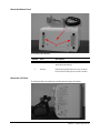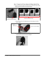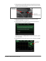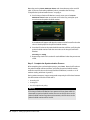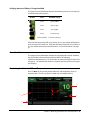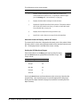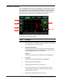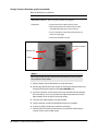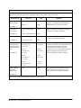
1
Integra® Camino® ICP Monitor Intracranial Pressure and Temperature Monitor USER’S MANUAL Caution Federal (USA) law restricts this device to sale by or on the order of a physician. Publication Name Integra Camino ICP Monitor User’s Manual Integra Part Number 60903733 Rev. B Effective Date September 2012 Trademark Acknowledgements Integra, the Integra logo, and Camino are registered trademarks of Integra LifeSciences Corporation or its subsidiaries in the United States and/or other countries. Delta-Cal is a trademark of Utah Medical Products, Inc. Sani-Cloth is a registered trademark of Professional Disposables International, Inc. Aptimax, Sealsure, and Sterrad are registered trademarks of Johnson and Johnson. Tyvec is a registered trademark of E.I. duPont. Kimguard and One-Step are registered trademarks of Kimberly-Clark Worldwide, Inc. 0086 Copyright Information ©2012 Integra LifeSciences Corporation. All rights reserved. No part of this document may be reproduced, stored in a retrieval system, or transmitted, in any form or by any means—electronic, mechanical, photocopying, recording, or otherwise—without the expressed, written consent of Integra LifeSciences Corporation. Additional copies of this document can be ordered from Integra LifeSciences Corporation. Manufacturer: Integra LifeSciences(Ireland) Limited IDA Business and Technology Park Sragh, Tullamore, County Offaly, Ireland Distributed by: Integra LifeSciences Corporation 311 Enterprise Drive Plainsboro, NJ 08536 USA Tel: 1-800-654-2873 (USA only) 1-(609) 275-0500 Fax: 1-609-275-5363 Internet Address: http://www.integralife.com Made in Ireland. Printed in Ireland. This page is intentionally left blank. TABLE OF CONTENTS List of Symbols and Abbreviations Packaging and Label Symbols ................................................................................................................v Software Symbols .................................................................................................................................. vi List of Abbreviations .............................................................................................................................. vii Chapter 1: System Overview Indications for Use / Intended Use ..........................................................................................................1 Contraindications ....................................................................................................................................1 Intended User..........................................................................................................................................1 Intended Patient Population ....................................................................................................................1 Description of the Integra Camino ICP Monitor.......................................................................................2 Key Functions of Monitor................................................................................................................2 Reviewing the User’s Manual..................................................................................................................2 List of Warnings for Using the Monitor ....................................................................................................3 Parts of the Monitor .................................................................................................................................6 About the Front Panel.....................................................................................................................6 About the Rear Panel .....................................................................................................................7 About the Right Panel.....................................................................................................................8 About the Bottom Panel..................................................................................................................9 About the Left Panel .......................................................................................................................9 Chapter 2: Setting Up System for the First Time Procedures for Initial Setup ...................................................................................................................11 Chapter 3: Setting Up System for Clinical Use Setting Up System for Clinical Use .......................................................................................................19 Positioning the Monitor .................................................................................................................19 Attaching to Equipment Pole (if applicable) ..................................................................................19 Powering the System On and Off .................................................................................................20 Using the Battery for Power..........................................................................................................21 Storing the Battery........................................................................................................................22 About the Integra Catheters ..................................................................................................................23 Connecting the Integra® Camino® Fiber Optic Catheters (110-4 Series) ..............................................24 Connecting the Integra® Camino® Flex Catheters .................................................................................27 Connecting to a Patient Bedside Monitor (if applicable) ......................................................................30 i Procedures for Synchronizing the Two Monitors ......................................................................... 30 About Pressure and Temperature Measurements on the Patient Bedside Monitor..................... 33 Storing the System ............................................................................................................................... 33 Chapter 4: Monitoring the Patient’s ICP and Temperature About the Touch Screen....................................................................................................................... 35 About the Synchronize to Monitor Button .................................................................................... 36 Reviewing the Status Bar............................................................................................................. 36 Verifying Status of Battery and AC Power .................................................................................. 36 Verifying Amount of Battery Charge Available............................................................................. 37 About the Alarms .................................................................................................................................. 37 Monitoring the Patient’s ICP and Temperature .................................................................................... 37 Monitoring Trend Data .......................................................................................................................... 39 Conditions that Reset Trend Data................................................................................................ 40 Setting the High ICP Alarm Limit .......................................................................................................... 41 Specifying the High ICP Alarm Limit ............................................................................................ 42 Disabling the High ICP Alarm ...................................................................................................... 43 Silencing the High ICP Alarm Temporarily................................................................................... 43 Restoring Default High ICP Alarm Limit Values........................................................................... 43 Customizing the User Settings ............................................................................................................. 44 Chapter 5: Responding to Physiological and Technical Alarms About the Two Alarm Types ................................................................................................................. 47 About the Technical Messages ............................................................................................................ 47 Understanding the Alarm Symbols ....................................................................................................... 48 How the Monitor Prioritizes the Alarms ............................................................................................... 48 Audio and Visual Indicators for Medium and Low Priority Alarms ............................................... 49 Priorities of Physiological and Technical Alarms ......................................................................... 49 List of Priorities for Each Alarm.................................................................................................... 50 Responding to the Physiological Alarm (ICP above alarm limit) .......................................................... 51 Responding to Technical Alarms .......................................................................................................... 51 Responding to Irreversible System Failure Alarms...................................................................... 51 Responding to ICP Catheter Failure Alarm.................................................................................. 52 Responding to Temperature Sensor Failure Alarm ..................................................................... 52 Responding to Low Battery Alarm ............................................................................................... 52 Responding to Monitor Overheating Alarm.................................................................................. 53 Responding to Cooling Fan Failure Alarm ................................................................................... 53 Responding to Accuracy Range Alarm ........................................................................................ 54 Responding to Battery Failure Alarm ........................................................................................... 55 ii Chapter 6: Extracting Trend Data for Remote Evaluation About Data Extraction ...........................................................................................................................57 Extracting Data to USB Drive ...............................................................................................................57 How the Monitor Stores Trend Data for Up to 5 Days ..................................................................58 Extract Data via Digital Streaming ........................................................................................................59 Conditions That Reset Trend Data During Recording...........................................................................59 Chapter 7: Cleaning and Sterilizing the System Cleaning the System and Components.................................................................................................61 Cleaning Guidelines .....................................................................................................................61 Sterilizing the Integra® Camino® Fiber Optic Catheter Cable ................................................................63 Sterilizing the Integra® Camino® Flex Extension Cable .........................................................................65 Sterilization Parameters ...............................................................................................................65 About Single-Use Only Catheters .........................................................................................................66 Disposal of the Monitor System and Components ................................................................................66 Chapter 8: Troubleshooting the System About the Troubleshooting Process ......................................................................................................67 Responding to System Status Messages .............................................................................................67 Responding to Problems During Use ....................................................................................................69 Responding to System Failure Messages.............................................................................................73 Chapter 9: Testing and Preventive Maintenance About These Procedures ......................................................................................................................75 Use Fiber Optic Catheters for Each Test......................................................................................75 Testing Pressure Input ..........................................................................................................................76 Using a Graduated Drainage Bag ................................................................................................76 Using a Pressure Simulator (preferred method) ...........................................................................78 Testing Pressure Output .......................................................................................................................79 Testing Temperature Input ....................................................................................................................80 Testing Temperature Output .................................................................................................................81 Testing High ICP Alarm Limit ................................................................................................................84 Testing AC Power and Battery Charge .................................................................................................85 AC Power .....................................................................................................................................85 Low Battery Alarm ........................................................................................................................85 Battery Charge .............................................................................................................................86 Inserting A New Battery ........................................................................................................................86 Determining Software Version ..............................................................................................................87 iii Testing Synchronizing to Patient Bedside Monitor ............................................................................... 87 Chapter 10: Contacting Integra for Technical Support and Annual Maintenance About Technical Support ...................................................................................................................... 89 About Annual Maintenance .................................................................................................................. 89 Appendix A: Technical Specifications List of Technical Specifications ............................................................................................................ 91 Classifications and Standards ............................................................................................................. 93 Manufacturer’s Declaration Table......................................................................................................... 94 General Notes.............................................................................................................................. 94 Appendix B: Integra Warranty Warranty .............................................................................................................................................. 99 Index .............................................................................................................................. 103 iv LIST OF SYMBOLS AND ABBREVIATIONS Packaging and Label Symbols Symbol Definition Symbol Definition Follow instructions for use Defibrillation-proof type CF applied part Catalogue number Direct current Caution: Federal (USA) law restricts this device to sale by or on the order of a physician. Class II equipment Serial number Waste Electronics and Electrical Equipment Batch code USB connection Manufacturer Safety information for transporting lithium ion batteries. Date of manufacture CALIBRATION VERIFIED. NEXT SCHEDULED MAINTENANCE DUE Due date for annual maintenance 72903759 Rev 1 +50°C l Temperature limitation -20°C List of Symbols and Abbreviations • v Software Symbols Symbol Description Symbol Definition Active alarm AC power not being used/available Audio paused Battery charge indicator Inactive alarm No battery connected or faulty battery High ICP alarm limit Battery being charged AC power being used System information panel On/Off power vi • List of Symbols and Abbreviations List of Abbreviations Abbreviation Definition AC Alternating Current ºC Celsius CAMCABL Preamplification cable used with Integra fiber optic catheters CSV Comma-separated values CT Computer tomography dB Decibels DC Direct Current DMM EtO ºF FLEX FLEXEXT Digital Multimeter Ethylene oxide Fahrenheit Flex Catheter Flex Extension Cable hPA Hectopascal pressure unit ICP Intracranial pressure ICT Intracranial temperature IPA Isopropyl alcohol LED Light Emmitting Diode mm Millimeters mmHg Millimeters of mercury MR Magnetic resonance OR Operating Room PMIO Patient Monitor Input Output TBI Traumatic brain injury USB Universal Serial Bus V Volt W Watt List of Symbols and Abbreviations • vii This page is intentionally left blank. viii • List of Symbols and Abbreviations CHAPTER 1 SYSTEM OVERVIEW Indications for Use / Intended Use ................................................................. 1 Contraindications ............................................................................................ 1 Intended User................................................................................................... 1 Intended Patient Population ........................................................................... 1 Description of the Integra Camino ICP Monitor ............................................ 2 Reviewing the User’s Manual ......................................................................... 2 List of Warnings for Using the Monitor ......................................................... 3 Parts of the Monitor ......................................................................................... 6 Indications for Use / Intended Use The Integra® Camino® ICP Monitor is indicated for use by qualified neurosurgeons or neurointensivists for measurement of intracranial pressure and temperature. Contraindications The Integra Camino ICP Monitor and its accessories are contraindicated for use in a Magnetic Resonance (MR) environment. Intended User The Integra Camino ICP Monitor is intended to be used by the following qualified medical and biomedical professionals: • A qualified neurosurgeon should perform the placement and handling of the catheters. • Designated qualified hospital staff (e.g. neurosurgeon, nurse, intensivist, trauma physician, or physician’s assistant) should perform the operation of the monitor. Chapter 9 provides instructions for testing and maintaining the monitor. The procedures in this chapter are intended to be performed by the hospital’s biomedical engineering staff. Intended Patient Population Patients undergoing treatment with this monitor under the cranial applications are expected to have had a TBI, undergone a major neurosurgical procedure, or some other traumatic, ischemic or hemorrhagic incident requiring controlled monitoring of ICP and brain temperature. Chapter 1 • System Overview • 1 Description of the Integra Camino ICP Monitor The Integra Camino ICP Monitor is a compact, portable device that provides tools for continuously determining and monitoring intracranial pressure (ICP) and intracranial temperature (ICT) directly in the brain, depending on which catheters are connected to the system. This monitor supports the following catheters: • Series of Integra® Camino® Fiber Optic Catheters (110-4 series) for measuring both ICP and temperature. • Integra® Camino® Flex Catheter for measuring ICP values. All Integra catheters measure their respective values at the tip of the catheter. This design eliminates the need for a fluid-filled system to communicate pressure (and carry pressure waves) to an external transducer. Key Functions of Monitor During clinical use, the Integra Camino ICP Monitor provides several key functions to facilitate the process for monitoring and analyzing patient data: • Touch screen interface for evaluating patient ICP/ICT data and setting patient parameters (see page 35) • Physiological alarm that activates if the patient’s Mean ICP value exceeds a user-specified limit for more than 5 seconds (see page 41) • Rechargeable lithium ion battery that supplies power to monitor during patient transport (see page 21) • Storage of patient’s ICP trend data for up to 5 days (see page 39) • Outputs for transferring patient data to a patient bedside monitor (see page 30) • Outputs for extracting patient data to remote media types via USB drive or digital streaming (see page 57) For instructions on using the Integra catheters, see the directions for use supplied with each respective catheter. Reviewing the User’s Manual Integra recommends that all physicians, nurses, and technicians who will be using, operating, and maintaining the Integra Camino ICP Monitor review this user’s manual prior to using the system. If there are additional questions after reading this manual, contact Integra. 2 • Chapter 1 • System Overview List of Warnings for Using the Monitor Failure to observe one or more of the following warnings could compromise patient safety or result in measurement errors. Warnings • Use of the Integra Camino ICP Monitor is restricted to one patient at a time. • The Integra Camino ICP Monitor and its accessories are contraindicated for use in a Magnetic Resonance (MR) environment. • Always verify the high ICP alarm limit is set appropriately for each patient prior to treatment. • Selecting the Alarm Off feature on the Alarm panel will disable the high ICP alarm limit indefinitely. Use caution if this feature is selected. To re-enable this alarm, press the Alarm On and Accept buttons. • No modification of the Integra Camino ICP Monitor is allowed. • The Integra Camino ICP Monitor is a sensitive electronic device. When using the monitor, always handle with care. If damage is suspected, contact Integra. • Read the user’s manual from the patient bedside monitor’s manufacturer before connecting the Integra Camino ICP Monitor to a patient bedside monitor. • To prevent injury to the patient, user, or other persons, or damage to the monitor, always verify that the monitor is clamped securely to the equipment pole. • To reduce the risk of electric shock, do not disassemble the Integra Camino ICP Monitor. Refer all servicing to qualified service personnel at Integra. • To prevent electrical shock, only use the AC power adapter supplied by Integra (REF # MONPWR). Using a different AC power adapter may not provide protection against electric shock. • Danger - Possible explosion hazard if used in the presence of flammable anaesthetics. • Only use Integra supplied accessories on the Integra Camino ICP Monitor. This applies in particular to catheters, catheter cables, battery, AC power adapter, and USB-to-R232 adapter cable. • If the Integra Camino ICP Monitor loses power and shuts down while it is connected to a patient bedside monitor, do not use the ICP values on the patient bedside monitor for patient measurements; the ICP values on the patient bedside monitor will be invalid. • Connect the monitor to an AC power supply immediately if the low battery alarm is activated. Chapter 1 • System Overview • 3 Warnings • When using the battery: - Do not heat above 80 °C. - Do not open battery. - Do not dispose of in fire. - Do not short circuit as battery may ignite, explode, leak, or get hot causing personal injury. - Replace battery with same part number only (REF # BAT1001). - Use of another battery may present a risk of fire or explosion. • To prevent injury to the patient, user, or other persons, make sure that the battery cover is closed securely during monitor use. • Do not connect an Integra Camino Fiber Optic Catheter and an Integra Camino Flex Catheter simultaneously to the monitor. The Integra Camino ICP Monitor is designed to report ICP measurements with either the Flex Catheter or Fiber Optic Catheter connected to the monitor, but not both together. • To prevent possible patient injury resulting from incorrect ICP measurements, always perform the steps listed on page 23 before implanting a new Integra Camino Fiber Optic Catheter into the patient. In particular, always make sure to adjust the new Fiber Optic Catheter’s ICP value to zero before implantation while the catheter is in the air. Never attempt to re-zero a catheter while the catheter is inside the patient. • Once the Integra Camino Fiber Optic Catheter has been zeroed to the Integra Camino ICP Monitor, do not replace the Fiber Optic Catheter Cable being used for patient measurement. Replacing the Fiber Optic Catheter Cable with another cable after the catheter has already been zeroed may result in inaccurate patient measurements. • Once the Integra Camino Fiber Optic Catheter has been zeroed to the Integra Camino ICP Monitor, do not transfer this zeroed catheter to any other monitor. Transferring a zeroed catheter to a different monitor may result in inaccurate ICP measurements. • To prevent possible patient injury resulting from incorrect ICP measurements, always perform each of the steps listed on page 26 before implanting a new Integra Camino Flex Catheter into the patient. In particular, always leave the Flex Catheter in the air until the monitor completes the autozero (i.e. initialization) process successfully. • Once the Integra Camino Flex Catheter has been initialized (autozeroed) by the Integra Camino ICP Monitor, do not replace the Integra Camino Flex Extension Cable being used for patient measurement. Replacing the Flex Extension Cable with another cable after the Flex Catheter has already been initialized may result in inaccurate ICP measurements. • Once the Integra Camino Flex Catheter has been initialized (i.e. autozeroed) by the Integra Camino ICP Monitor, do not transfer this initialized catheter to any other monitor. Transferring an initialized catheter to a different monitor may result in inaccurate ICP measurements. 4 • Chapter 1 • System Overview Warnings • The Integra Camino ICP Monitor will only store the Mean ICP data from the most recent 5 days. All stored trend data older than 5 days will be lost. If monitoring is continued for more than 5 days, placement of a new catheter under sterile conditions is recommended. Note that replacing a catheter will reset the trend data. Please extract any data that you wish to retain prior to replacing the catheter. • Do not autoclave or immerse the Integra Camino ICP Monitor in liquid as damage may occur. If the monitor is exposed to liquids, turn off the unit, remove the AC power adapter, dry the unit thoroughly, and send to biomed staff for evaluation before reapplying power. • Only use the cleaning agents listed in Chapter 7 for cleaning and disinfecting the Integra Camino ICP Monitor system. Using solvents or cleaning agents not listed in Chapter 7 may damage the plastic exterior of the Integra Camino ICP Monitor. Chapter 1 • System Overview • 5 Parts of the Monitor The Integra Camino ICP Monitor contains hardware, software, and electrical components that support specific Integra catheters for monitoring the patient’s ICP and temperature. The following section provides information on the different parts of the monitor. About the Front Panel 1 2 3 4 The front panel contains: Number 6 • Chapter 1 • System Overview Item Description 1 Handle Handle used for carrying the monitor. 2 Power Status Green LED button that indicates the monitor is being powered by the AC power adapter. Note that this button does not illuminate if the monitor is being powered by the battery. 3 Power Button Turns the monitor on and off. This button is illuminated when the power is on. 4 Touch Screen Provides software tools for viewing data and controlling parameters for monitoring the patient’s ICP and ICT levels. About the Rear Panel 1 5 2 6 3 4 The rear panel contains: Number Item Description 1 USB Port Connection port for extracting trend data via USB transfer or digital streaming. 2 AC Power Adapter Port Connection port for the AC power cord. 3 PMIO Port Connection port for PMIO cable. This cable is used to connect the Integra Camino ICP Monitor to a patient bedside monitor. 4 Pole Clamp Clamping system for securing monitor to an equipment pole. 5 Air Vent Grated opening that allows air being circulated by the internal cooling fan to leave the monitor. 6 Cable Strap Rubber strap used to secure AC power adapter during transport. Chapter 1 • System Overview • 7 About the Right Panel 1 2 3 The right panel contains: Number 8 • Chapter 1 • System Overview Item Description 1 Temperature Port Connection port for the temperature connector on the Fiber Optic Catheter Cable. 2 Pressure Port Connection port for the ICP connector on the Integra Camino Flex Extension Cable (pressure only). 3 Pressure Port Connection port for the ICP connector on the Fiber Optic Catheter Cable. About the Bottom Panel 1 2 The bottom panel contains: Number Item Description 1 Battery Door Cover Removable cover for accessing/replacing the 14.4V lithium ion battery. 2 Air Vent Grated opening that allows air being circulated by the internal cooling fan to leave the monitor. About the Left Panel The left panel does not contain any usable connector ports or buttons. Chapter 1 • System Overview • 9 This page is intentionally left blank. 10 • Chapter 1 • System Overview CHAPTER 2 SETTING UP SYSTEM FOR THE FIRST TIME Procedures for Initial Setup Step 1: Unpack the System (REF # CAM02) Remove the contents from the Integra® Camino® ICP Monitor shipping box and verify the following items are included. Warning Only use Integra supplied accessories on the Integra Camino ICP Monitor. This applies in particular to catheters, catheter cables, battery, AC power adapter, and USB-to-R232 adapter cable. Content Description • Integra Camino ICP Monitor • Quantity = 1 • AC power adapter (18 V DC , 1.67 A, 30 W) • REF # MONPWR • Quantity = 1 • 14.4 V lithium ion battery • REF # BAT1001 • Quantity = 1 Chapter 2 • Setting Up System for the First Time • 11 Content Description • Integra® PMIO patient bedside monitor cable • REF # PMIOMPM • Quantity = 1 • Integra® Camino® Fiber Optic Catheter Cable • REF # CAMCABL • Quantity = 1 • Integra® Camino® Flex Extension Cable • REF # FLEXEXT • Quantity = 1 • USB-to-RS232 adapter cable • REF # EXPORTCAB • Quantity = 1 • User manual • REF # UM-CAM02XX (where XX refers to the country’s language code) • Quantity = 1 After unpacking the contents, inspect the shipment for any signs of damage or loss. If any damages are discovered, notify the carrier, the supplier, and retain all shipping cartons for examination. 12 • Chapter 2 • Setting Up System for the First Time Step 2: Install the Battery Perform the following steps with a Phillips screwdriver and the Integra-supplied 14.4 V lithium ion battery. 1. Make sure the monitor is unplugged and turned off. 2. Turn the monitor upside down so the handle is facing downward. 3. Remove the 2 screws to take off the battery cover. 4. Verify the Integra logo on the battery is facing up and insert the battery: A. Align the battery’s connectors on the front of the battery to the connector slots on the monitor. B. Slide the battery’s connector into the monitor’s connector slots until the battery is fully inserted into place. 5. Secure the battery cover to the monitor by re-inserting the two small screws. Chapter 2 • Setting Up System for the First Time • 13 Step 3: Prepare the AC Power Adapter with Region-Specific Plug 1. Remove the AC power adapter from the package and attach the region-specific adapter plug to the backside of the AC power adapter. US UK Europe Australia Region-Specific Adapter Plugs Backside of AC power adapter A. Align the two slots on the adapter plug over the two prongs on the AC power adapter. Slots on adapter plug Prongs on AC power adapter B. Push the adapter plug down over the two prongs until the entire base of the plug sits flush against the AC power adapter. 14 • Chapter 2 • Setting Up System for the First Time C. Gently slide the adapter plug forward until it snaps into place. 2. To remove the adapter plug, press the release button on the AC power adapter and pull the plug away from the adapter. Press the release button to remove adapter plug Step 4: Plug the Monitor into AC Power Perform the following steps with the Integra-supplied AC power adapter: 1. Place the monitor on a flat surface. 2. Connect the AC power adapter to the Integra Camino ICP Monitor: A. On the back of the monitor, attach the connector end of the AC power . adapter into the port labeled Input: 18 V Connector end of AC power adapter B. Insert the plug end of the AC power adapter into a grounded AC wall outlet. 3. Turn on the monitor. On the front of the monitor, press the power button; the Integra Camino ICP Monitor will display the Integra logo before initiating the monitor setup process. Chapter 2 • Setting Up System for the First Time • 15 4. After the initial setup process completes, the Integra Camino ICP Monitor sounds a one-second startup tone and displays the Main panel on the touch screen. Caution The purpose of the startup tone verifies that the audio alarms are functioning correctly. If this tone does not sound during the startup process, contact Integra for service. Step 5: Set the Time and Date 1. On the touch screen, press the Settings tab and select Set Time and Date. 2. On the displayed panel, press the desired field (hour, minutes, date, month, or year) and use the arrows to specify the appropriate setting. Note that you may adjust each of these settings prior to accepting them in the following step. 3. Press Accept; the Integra Camino ICP Monitor will display the selected time/date on the touch screen. Step 6: Specify the Language 1. On the touch screen, press the Settings tab (fourth tab from the left) Settings tab 2. Press Set Language. Set Language button 16 • Chapter 2 • Setting Up System for the First Time 3. In the displayed Language: menu, use the arrows to select the desired language. 4. Press Accept; the Integra Camino ICP Monitor will display all of the text that appears on the touch screen in the selected language. Step 7: Use AC Power to Charge the Battery to Full Capacity 1. Turn off the monitor. On the front of the monitor, press the power button. 2. Keep the Integra Camino ICP Monitor on AC power with the monitor turned off for 5 hours. This will re-charge the battery to full capacity. 3. After 5 hours, turn on the monitor by pressing the power button. 4. On the touch screen, view the battery power symbol on the status bar to verify the symbol displays four green bars; this indicates the battery has full charge. Chapter 2 • Setting Up System for the First Time • 17 This page is intentionally left blank. 18 • Chapter 2 • Setting Up System for the First Time CHAPTER 3 SETTING UP SYSTEM FOR CLINICAL USE Setting Up System for Clinical Use .............................................................. 19 About the Integra Catheters ......................................................................... 23 Connecting the Integra® Camino® Fiber Optic Catheters (110-4 Series) 24 Connecting the Integra® Camino® Flex Catheters .................................... 27 Connecting to a Patient Bedside Monitor (if applicable) ........................... 30 Storing the System ........................................................................................ 33 Setting Up System for Clinical Use The following section contains instructions for positioning the monitor, powering the monitor, and connecting catheters to the monitor prior to clinical use. Positioning the Monitor The Integra® Camino® ICP Monitor is intended to be positioned on a hard flat surface or securely clamped to an equipment pole or bed support next to the patient. The distance between the patient and the monitor is restricted by the length of the Integra catheter cable. It is not permitted to extend the Integra catheter cable with non-Integra extension cables. Caution To prevent the monitor from overheating: • Do not block the air vents on the rear and bottom of the unit • Do not place the monitor on a soft or uneven surface, which may result in blockage of the monitor’s air vents. For example, do not place the monitor on the bed during patient transport. Attaching to Equipment Pole (if applicable) The Integra Camino ICP Monitor includes a clamp for attaching the monitor to an equipment pole. To attach: 1. On the rear of the monitor, fit the pole clamp around the equipment pole. Chapter 3 • Setting Up System for Clinical Use • 19 2. Tighten the knob on the pole clamp to secure the monitor to the equipment pole. Pole clamp attached to equipment pole Pole Clamp Note that the pole clamp supports equipment poles between 0.5 and 1.2 inches (12.7 and 30.5 mm) in diameter. Warning To prevent injury to the patient, user, or other persons, or damage to the monitor, always verify that the monitor is clamped securely to the equipment pole. Caution To prevent liquid from dripping inside the monitor and damaging the internal components, do not mount the monitor underneath an I.V. bag or tube feed. If liquid does drip onto the monitor, dry the monitor immediately. Powering the System On and Off Turning On the System Warning To prevent electrical shock, only use the AC power adapter supplied by Integra (REF # MONPWR). Using a different AC power adapter may not provide protection against electric shock. 1. Plug the monitor to an AC power outlet: A. On the back of the monitor, attach the connector end of the AC power . adapter into the port labeled Input: 18 V Connector end of AC power adapter AC power adapter 20 • Chapter 3 • Setting Up System for Clinical Use B. Insert the plug end of the AC power adapter into a grounded AC wall outlet. 2. Turn on the monitor: A. On the front of the monitor, press the power button. B. Once the button illuminates, the Integra logo will appear on the touch screen for a few seconds before initiating the setup process. Power Button 3. After the setup process completes, the monitor will sound a one-second startup tone and display the Main panel: Caution The purpose of the startup tone verifies that the audio alarms are functioning correctly. If this tone does not sound during the startup process, contact Integra for service. Warning To prevent injury to the patient, user, or other persons, or damage to the monitor, make sure to position the cables so that they are free from all foot traffic. Turning Off the System On the front of the monitor, press the power button. If the monitor ever freezes and does not turn off, press and hold the power button for several seconds to perform a forced shutdown of the system. Using the Battery for Power The Integra Camino ICP Monitor includes a rechargeable 14.4 V lithium ion battery that supplies power to the monitor for at least 1.5 hours when the battery is fully charged; the battery is only intended for use during patient transport. • To charge the battery to full capacity, turn off the monitor and plug it into an AC outlet for at least 5 hours prior to use. • To ensure the battery maintains charge during patient use, always plug the monitor to an AC outlet whenever possible. If the battery exhibits problems powering the monitor for 1.5 hours, perform the "Battery Charge" test on page 86 to ensure the battery is functioning properly. Battery Power Indicator On the touch screen, a battery power indicator appears in the status bar that displays the amount of battery charge available (see page 36). • If the battery charge level drops to 15 minutes or less, the monitor will activate visual warnings. • If the battery charge level drops to 5 minutes or less, the monitor will sound an alarm. Chapter 3 • Setting Up System for Clinical Use • 21 For more information on responding to low battery alarms, see page 52. For specific information on testing/replacing the battery, see page 85. Warning When using the battery: • Do not heat above 80 °C. • Do not open battery. • Do not dispose of in fire. • Do not short circuit as battery may ignite, explode, leak, or get hot causing personal injury. • Replace battery with same part number only (REF # BAT1001). • Use of another battery may present a risk of fire or explosion. Warning To prevent injury to the patient, user, or other persons, make sure that the battery cover is closed securely during monitor use. Caution To ensure appropriate battery power with use of the Integra Camino ICP Monitor, only use batteries supplied by Integra (REF # BAT1001). To order replacement batteries, contact Integra. Notice The Integra Camino ICP Monitor has been designed to operate during use while a battery is installed in the unit (even if the battery is not being used for power). As a result, always use the monitor with a battery installed. Storing the Battery If the Integra Camino ICP Monitor will not be used for several months or longer, remove the battery from the monitor prior to storing the monitor. Ensure the battery is stored in a cool, dry, and well-ventilated area. Notice If the Integra Camino ICP Monitor is not used for a long duration of time, the battery will lose charge. Always make sure the battery is charged to full capacity prior to use. The Integra Camino ICP Monitor will charge the battery while the monitor is plugged into AC power. 22 • Chapter 3 • Setting Up System for Clinical Use About the Integra Catheters The Integra Camino ICP Monitor supports the following Integra catheters: Catheter Measurements Description Integra Camino Fiber Optic (110-4 Series) ICP/Temperature Fiber optic pressure/temperature catheters and pressure transducer-tipped catheters. Integra Camino Flex ICP A silicon strain gauge pressure transducer-tipped 9/10 FR catheter. For complete instructions on using catheters, see the directions for use supplied by Integra with each respective catheter. Warning Do not connect a Fiber Optic Catheter and a Flex Catheter simultaneously to the monitor. The Integra Camino ICP Monitor is designed to report ICP measurements with either the Flex Catheter or Fiber Optic Catheter connected to the monitor, but not both together. Chapter 3 • Setting Up System for Clinical Use • 23 Connecting the Integra® Camino® Fiber Optic Catheters (110-4 Series) Connecting the Fiber Optic Catheters (110-4 series) to the Integra Camino ICP Monitor requires the Integra Camino Fiber Optic Catheter Cable (REF # CAMCABL): Warning To prevent possible patient injury resulting from incorrect ICP measurements, always perform each of the following steps before implanting a new Fiber Optic Catheter into the patient. In particular, always make sure to adjust the new Fiber Optic Catheter’s ICP value to zero before implantation while the catheter is in the air. Never attempt to change the zero adjustment while the catheter is inside the patient. Notice Before implanting the catheter into the patient, ensure that the temperature is at a reasonable value, such as room temperature. To connect: 1. On the monitor’s right side, connect the Fiber Optic Catheter Cable to the ICP and temperature ports: Temperature connector from catheter cable Pressure connector from catheter cable Fiber Optic Catheter Cable A. Attach the cable’s ICP connector (P) into the port labeled ICP (CAMCABL). To attach: • Align the red dot on the cable connector with the red triangle on the monitor’s port and push firmly. • Verify the cable is completely connected to the monitor before proceeding. B. If temperature will be monitored for the patient, attach the cable’s temperature connector (T) into the port labeled ICT (CAMCABL). To attach: • Align the red dot on the cable connector with the red triangle on the monitor’s port and push firmly. • Verify the cable is completely connected to the monitor before proceeding. 24 • Chapter 3 • Setting Up System for Clinical Use 2. When operating in the sterile field, select the desired Integra® Camino® Pressure Monitoring Kit (model 110-4 series). For instructions on using the kit, see the directions for use supplied with each kit. 3. Remove the catheter from its sterile tray and firmly attach its ICP and temperature connections to the Fiber Optic Catheter Cable: A. Attach the ICP transducer from the catheter to the ICP connector on the Fiber Optic Catheter Cable. B. If applicable, attach the temperature thermistor from the catheter to the temperature connector on the Fiber Optic Catheter Cable. Temperature connector from catheter cable Temperature thermistor from catheter ICP connector from catheter cable ICP transducer from catheter 4. Note that when the temperature catheter is first connected and in open air (room temperature), the Integra Camino ICP Monitor will: • Sound an alarm; and • Display "Temperature out of accuracy range" on the status bar. To silence the alarm temporarily (3 minutes) while the catheter is still in air, press the yellow alarm button. 5. Verify that the ICP value reads 0 mmHg on the monitor. To verify, press the Main tab on the touch screen and view the ICP value. If the ICP value does not read 0 mmHg: A. Press the Scale button on the Main tab to select a waveform range of -10 to 20 mmHg. Note that pressing the Scale button each time advances to the next range. B. Remove the black zero adjustment tool from the catheter kit. C. Use the tool to adjust the screw located on the bottom of the catheter’s transducer to increase/decrease the ICP value. Transducer from catheter Zero adjustment tool D. Set the ICP value to 0 mmHg. Chapter 3 • Setting Up System for Clinical Use • 25 6. Prior to implanting the catheter into the patient, disconnect the Fiber Optic Catheter from the Fiber Optic Catheter Cable. 7. After implanting the catheter into the patient, reconnect the catheter to the Fiber Optic Catheter Cable. Warning Once the Fiber Optic Catheter has been zeroed to the Integra Camino ICP Monitor, do not replace the Fiber Optic Catheter Cable being used for patient measurement. Replacing the Fiber Optic Catheter Cable with a different cable after the ICP catheter has already been zeroed may result in inaccurate patient measurements. Warning Once the Fiber Optic Catheter has been zeroed to the Integra Camino ICP Monitor, do not transfer this zeroed catheter to any other monitor. Transferring a zeroed catheter to a different monitor may result in inaccurate ICP measurements. Notice If the patient only requires an ICP catheter, the temperature value on the touch screen will appear blank (with two dashed lines). 26 • Chapter 3 • Setting Up System for Clinical Use Connecting the Integra® Camino® Flex Catheters Connecting the Integra Camino Flex Catheter to the Integra Camino ICP Monitor requires the Integra Camino Flex Extension Cable (REF # FLEXEXT). Warning To prevent possible patient injury resulting from incorrect ICP measurements, always perform each of the following steps before implanting a new Integra Camino Flex Catheter into the patient. In particular, always leave the Flex Catheter in the air until the monitor successfully completes the initialization (i.e. autozero) process. To connect: 1. On the monitor’s right side, attach the end of the Flex Extension Cable closest the black barrel to the port labeled ICP (FLEXEXT). Black Barrel Connect to Monitor Flex Extension Cable 2. Remove the Flex Catheter from its packaging. For complete instructions on using this catheter, see the directions for use supplied in the Flex Catheter packaging. Chapter 3 • Setting Up System for Clinical Use • 27 3. When operating in the sterile field, attach the male end of the Flex Catheter connector to the female end of the Flex Extension Cable connector (note the alignment arrows on each connector): Male end of Flex Catheter Female end Flex Extension Cable 4. When attached correctly, the Integra Camino ICP Monitor will display "Catheter is initializing" in the status bar. 5. Verify the following message appears to ensure that the initialization (i.e. autozero) process has successfully completed: If the monitor reports a "Catheter failure" message in the status bar, replace with a new catheter. 6. Press Accept; the ICP value, which may be non-zero, will appear on the Main panel. ICP value on Main panel 28 • Chapter 3 • Setting Up System for Clinical Use Notice Note the ICP value displayed may be non-zero; this value reflects the hydration offset of the catheter while it is still in air. This value will self-adjust automatically when the catheter is implanted into the patient. 7. Prior to implanting the catheter into the patient, disconnect the Flex Catheter from the Flex Extension Cable. This will prevent the monitor from measuring ICP while the catheter is traveling, which may trigger alarms caused by the sudden changes in pressure (see the following section for details). 8. After implanting the catheter into the patient, reconnect the Flex Catheter to the Flex Extension Cable. Warning Once the Flex Catheter has been initialized (i.e. autozeroed) by the Integra Camino ICP Monitor, do not transfer this initialized catheter to any other monitor. Transferring an initialized catheter to a different monitor may result in inaccurate ICP measurements. Warning Once the Flex Catheter has been initialized (i.e. autozeroed) by the Integra Camino ICP Monitor, do not replace the Flex Extension Cable being used for patient measurement. Replacing the Flex Extension Cable with a different cable after the Flex Catheter has already been initialized may result in inaccurate ICP measurements. Transient Pressure Changes During Implantation or Removal of Catheter May Trigger Alarm If the Flex Catheter is connected to the monitor during the implantation or removal of a catheter, a sudden change in ICP measurements may occur while the catheter is traveling. Depending on the level of pressure change, the ICP measurements may temporarily exceed the ICP accuracy range for the monitor (between -10 mmHg and 125 mmHg) and trigger one of the following alarms: • "ICP out of accuracy range"; or • "ICP catheter failure" If either of these alarms is triggered during implantation or removal of the catheter, disconnect and re-connect the Flex Catheter to the Flex Extension Cable. Chapter 3 • Setting Up System for Clinical Use • 29 Connecting to a Patient Bedside Monitor (if applicable) The Integra Camino ICP Monitor provides outputs for connecting to a patient bedside monitor. This connection requires two Integra cables: Cables REF # Description PMIO PMIOMPM Main cable for connecting Integra monitor to patient bedside monitor. Monitor Adapter Cable ICPXX and ICTXX Adapter cables that fit between the PMIO cable and the vendor-specific patient bedside monitor. To determine which monitor adapter cables are required for your particular patient bedside monitor, contact Integra (see page 89). Warning Read the user’s manual from the patient bedside monitor’s manufacturer before connecting the Integra Camino ICP Monitor to a patient bedside monitor. Procedures for Synchronizing the Two Monitors Perform the following steps to verify that both the Integra Camino ICP Monitor and the patient bedside monitor report the same ICP values, ±1 mmHg or 1 % of 1 monitor reading (whichever is greater). Note that these steps should be performed in each of the following situations: • When first connecting the Integra Camino ICP Monitor to a patient bedside monitor. • If the Integra Camino ICP Monitor becomes disconnected from a patient bedside monitor (e.g. due to patient transport to CT or OR), and then needs to be re-connected. • If, during use, the reported ICP values between the Integra Camino ICP Monitor and the patient bedside monitor differ by more than ± 1 mmHg or 1 % of monitor reading (whichever is greater). Step 1: Connect the Two Monitors Notice To cancel the synchronization process during any of the following steps, press Done. Connect the Integra Camino ICP Monitor to the patient bedside monitor: A. On the rear panel of the Integra monitor, attach the connector end of the PMIO cable to the port labeled PMIO. 1. If the ICP value is above 100 mmHg, the difference between both monitors can differ by 2 mmHg. 30 • Chapter 3 • Setting Up System for Clinical Use • Align the red dot on the PMIO cable connector with the red triangle on the monitor’s port and push firmly. • Verify the cable is completely connected to the monitor before proceeding. AC power adapter cable PMIO cable B. On the other end of the PMIO cable, attach the monitor adapter cable for pressure (and temperature if applicable). C. Attach the PMIO cable and adapter cable to the temperature/pressure modules on the patient bedside monitor. Notice The Integra Camino ICP Monitor does not measure Cerebral Perfusion Pressure (CPP) ranges. As a result, the CPP connector on the PMIO cable will not be used. Step 2: Press the "Synchronize to Monitor" Button On the Integra Camino ICP Monitor’s touch screen, press the Synchronize to Monitor button; the Integra monitor will transmit an ICP value of 0 mmHg for up to one minute. A countdown will appear to display the amount time left to zero the patient bedside monitor. Step 3: Zero the Patient Bedside Monitor to the Integra Monitor On the patient bedside monitor, follow the manufacturer’s instructions to zero the monitor. Step 4: Check Additional Values to Confirm Synchronization Notice The following synchronization checks at 25 mmHg, 50 mmHg, and 100 mmHg are not required, but are recommended by Integra. On the Integra ICP Camino’s touch screen, press the Check Additional Values button to transmit additional ICP values to the patient bedside monitor for scaling verification: • 25 mmHg • 50 mmHg • 100 mmHg Chapter 3 • Setting Up System for Clinical Use • 31 Note that pressing Check Additional Values each time advances to the next ICP value. If you are not checking additional values, proceed to the final step, "Complete the Synchronization Process" on page 32. A. On the Integra Camino ICP Monitor’s touch screen, press the Check Additional Values button to transmit an ICP value at 25 mmHg for up to one minute to the patient bedside monitor. A countdown will appear to display the amount time left to confirm that the value is also displayed on the patient bedside monitor. B. Once the ICP value on the patient bedside monitor stabilizes, verify that the patient bedside monitor reads the same value as the Integra Camino ICP Monitor: 25 mmHg, ± 1 mmHg C. Repeat steps A to B in this section for each additional value that you want to check. Step 5: Complete the Synchronization Process After completing the synchronization process, press Done. Once the ICP value on the patient bedside monitor stabilizes, verify that the patient bedside monitor reads the same ICP value as the Integra Camino ICP Monitor (±1 mmH or 1 % of monitor reading, whichever is greater). During patient treatment, Integra recommends comparing the ICP values between the two monitors while the clinical staff is: • Recording ICP • Treating ICP • Per the hospital’s unit policy. Warning If the Integra Camino ICP Monitor loses power and shuts down while it is connected to a patient bedside monitor, do not use the ICP values on the patient bedside monitor for patient measurements; the ICP values on the patient bedside monitor will be invalid. 32 • Chapter 3 • Setting Up System for Clinical Use Notice After completing the synchronization process, always use the Integra Camino ICP Monitor’s measurements over the patient bedside monitor’s measurements. If drift occurs between the two monitors, use the Integra Camino ICP Monitor’s ICP values for the patient’s measurements and repeat the procedures for synchronizing the two monitors (see page 30). About Pressure and Temperature Measurements on the Patient Bedside Monitor The Integra Camino ICP Monitor is designed to measure tissue pressure between the range of -10 mmHg to 125 mmHg, and tissue temperature between the range of 30 °C and 42 °C. If the pressure or temperature value is outside these specific ranges on the Integra Camino ICP Monitor while it is connected to the patient bedside monitor, the Integra monitor will activate a low priority alarm for either an ICP or temperature accuracy range alarm condition (see page 54). Depending on the type of alarm condition, the Integra monitor will also transmit either a pressure value of -15 mmHg or a temperature value of 15 °C to the patient bedside monitor to indicate that the Integra monitor is unable to make accurate measurements. Storing the System If the Integra Camino ICP Monitor will not be used for several months or longer, remove the battery from the monitor prior to storing the monitor. During storage, keep the monitor in a dry location that meets the following environmental conditions: • Temperature: -20 °C to 50 °C • Humidity: 25% to 80% RH, non-condensing Also ensure the storage location is safe from any liquids that may drip inside the monitor and damage its internal components. Using the Cable Strap to Wrap the AC Power Adapter The Integra Camino ICP Monitor also includes an adjustable strap for securing the AC power adapter cord during patient transport or storage. To use this cable strap, wrap the rubber strap around the bundled adapter cord and secure it by inserting the round plastic fastener through the desired hole. Cable strap AC power adapter cord Chapter 3 • Setting Up System for Clinical Use • 33 This page is intentionally left blank. 34 • Chapter 3 • Setting Up System for Clinical Use CHAPTER 4 MONITORING THE PATIENT’S ICP AND TEMPERATURE About the Touch Screen ............................................................................... 35 About the Alarms........................................................................................... 37 Monitoring the Patient’s ICP and Temperature........................................... 37 Monitoring Trend Data .................................................................................. 39 Setting the High ICP Alarm Limit ................................................................. 41 Customizing the User Settings..................................................................... 44 About the Touch Screen The Integra® Camino® ICP Monitor includes a touch screen for evaluating and controlling parameters for monitoring the patient’s ICP and temperature. The touch screen provides the following tabs for accessing and activating different parameter: Tab Description Main Provides tools for evaluating the patient’s Mean ICP (mmHg) and temperature (°C). For details, see page 37. Trend Provides tools for monitoring for up to a 5-day history of the patient’s intracranial pressure values. For details, see page 39. Alarm Provides tools for specifying a high ICP alarm limit the monitor will tolerate before sounding an alarm. For details, see page 37. Settings Provides tools for specifying languages, date and time. This panel also contains settings for specifying the animated waveform graph that appears on the Main panel. For details, see page 44. Chapter 4 • Monitoring the Patient’s ICP and Temperature • 35 About the Synchronize to Monitor Button If you are planning to display patient data from the Integra Camino ICP Monitor to a patient bedside monitor, press the Synchronize to Monitor button to initiate the process of synchronizing the two monitors with each other. This process ensures that both monitors are displaying identical ICP values for the patient. Note that this feature provides synchronization checks at 0 mmHg, 25 mmHg, 50 mmHg, and 100 mmHg. Pressing the Check Additional Values button each time will advance to the next measurement. For instructions on synchronizing the monitors, see page 30. Reviewing the Status Bar When using the Integra Camino ICP Monitor, the status bar on the bottom of the touch screen will display messages to indicate the current states of alarms, catheters, and AC/battery power. Status bar Verifying Status of Battery and AC Power The Integra Camino ICP Monitor may be powered by either AC power or battery charge. To determine the status of power for the monitor, view the battery and plug symbols that appear on the bottom right of the touch screen: Symbol Status Indicates AC power is being used. Indicates AC power is not being used/available. Indicates battery power is being used to power the monitor. Each green bar represents the level of remaining battery charge (see following section). Indicates AC power is being used to charge the battery. Indicates that either a battery is not connected or a battery is not functioning properly. For instructions on powering the monitor, see page 20. 36 • Chapter 4 • Monitoring the Patient’s ICP and Temperature Verifying Amount of Battery Charge Available The Integra Camino ICP Monitor displays the following symbols on the status bar to indicate battery charge levels Symbol Color Available Charge Green 75% to 100% Green 50% to 75% Green 25% to 50% Green Less than 25% Flashing Yellow Less than 5 minutes If the level of battery charge falls to 15 minutes or less, the monitor will display an error message on the status bar. If the level of battery charge falls to 5 minutes or less, the monitor will activate a technical alarm. For more information, see page 52. About the Alarms The Integra Camino ICP Monitor activates one physiological alarm for exceeding the high ICP alarm limit and several technical alarms for indicating equipment-related problems. For instructions on setting the high ICP alarm limit, see page 41. For detailed information on responding to each of these alarm types, see Chapter 5. Monitoring the Patient’s ICP and Temperature Press the Main tab to view the patient’s Mean ICP and temperature values as numerical data. The ICP may also be viewed as an animated waveform. 2 3 1 4 5 Chapter 4 • Monitoring the Patient’s ICP and Temperature • 37 The information on this screen includes: Parameter Description 1 Displays a graph showing the ICP in mmHg versus time as an animated waveform (solid or line). To specify the waveform type, press the Settings tab. For instructions, see page 45. 2 Displays the Mean ICP in mmHg as numerical values. 3 Displays the high ICP alarm limit for the patient. If the patient’s Mean ICP exceeds this limit for more than 5 seconds, an alarm will sound. To specify this limit, see page 42. 4 Displays tissue temperature in degrees Celsius (°C). 5 Specifies the scales of pressure ranges for the ICP waveform. About the Numerical Display of Mean ICP Values The numerical ICP value that is displayed on the touch screen is the patient’s Mean ICP value, which is a time-averaged representation of the continuously measured ICP. This displayed value is rounded to the nearest 1 mmHg. Scaling the ICP Waveform Ranges If the ICP waveforms on the Main panel require resizing for clarity, press the Scale button to specify different waveform ranges. The ranges include: Ranges (mmHg) Increments (mmHg) 0 to 30 5 0 to 50 10 0 to 100 10 0 to 150 25 -10 to 20 5 Pressing the Scale button each time advances to the next range. Note that the purpose of the -10 to 20 mmHg range is to provide appropriate scaling when zeroing the Fiber Optic Catheter (see page 24 instructions on zeroing the Fiber Optic Catheter). 38 • Chapter 4 • Monitoring the Patient’s ICP and Temperature Monitoring Trend Data Press the Trend tab to view a graph of recorded Mean ICP trend data in mmHg at one-minute intervals. The Integra Camino ICP Monitor stores up to five days of trend data that may be viewed in specific ranges of time. This data may also be extracted from the monitor to other media types by either USB transfer or by digital streaming. For instructions on extracting data, see page 57. 1 6 2 7 3 8 4 5 The information on this panel includes: Items 1 Description Extract Data Copies the patient’s trend data to a USB drive that has been connected to the USB port on the rear of the monitor. 2 Data Streaming Enabled Indicates that the feature for streaming patient trend data digitally to another media type has been activated. This feature requires the use of the USB-to-RS232 adapter cable (see Chapter 6). 3 ICP Scale Specifies the range of the ICP values displayed on the Trend graph. 4 Time Scale Specifies the range of time displayed on the Trend graph. 5 Displays the patient’s ICP trend data. 6 Displays Mean ICP in mmHg as a numerical value. 7 Displays the high ICP alarm limit. If the patient’s Mean ICP value exceeds this limit for more than 5 seconds, an alarm will sound. To specify this limit, see page 42. 8 Displays tissue temperature in degrees Celcius (°C). Chapter 4 • Monitoring the Patient’s ICP and Temperature • 39 Scaling Time Ranges for Trend Data Press the Time Scale button to specify different time ranges to view the trend data. The time ranges include: • 3 hours • 12 hours • 24 hours • 48 hours • 120 hours Pressing the Time Scale button each time advances to the next time range. Scaling the ICP Ranges for Trend Data If the ICP waveforms on the Trend panel require resizing for optimal viewing, press the ICP Scale button to specify different waveform ranges. The ranges include: Ranges (mmHg) Increments (mmHg) 0 to 30 5 0 to 50 10 0 to 100 10 0 to 150 25 -10 to 20 5 Pressing the ICP Scale button each time advances to the next waveform range. Conditions that Reset Trend Data Depending on the catheter type, some conditions may result in the loss of trend data during the recording process. For details, see page 59. 40 • Chapter 4 • Monitoring the Patient’s ICP and Temperature Setting the High ICP Alarm Limit Press the Alarm tab to specify settings for controlling the physiological alarm. This panel includes arrows for specifying the high ICP alarm limit value, turning the alarm on and off, and restoring the high ICP alarm limit from a customized setting to the factory default setting (20 mmHg). 1 5 2 3 4 6 The information on this panel includes: Item 1 Description Alarm On Activates the physiological alarm settings. If this option is selected, the monitor will sound an alarm if the patient’s displayed Mean ICP exceeds the specified high ICP alarm limit for more than 5 seconds. By default, this option is selected and set to 20 mmHg. 2 Alarm Off Deactivates the physiological alarm settings. If this option is selected, the monitor will disable the high ICP alarm and prevent a high ICP alarm from sounding. In this mode, the monitor will display ICP Alarm Off in the status bar. Note that technical alarms cannot be disabled with this option. 3 High ICP Alarm Limit Specifies the maximum ICP value that the monitor will tolerate before activating the alarm. To specify this limit, press the arrows to a value between -10 mmHg and +125 mmHg in 1 mmHg increments. 4 Restore Defaults Restores customized settings for the high ICP alarm limit to the factory default settings (20 mmHg). Pressing this button also activates the Alarm On button. 5 ICP Displays the Mean ICP in mmHg as numerical values. 6 Temperature Displays tissue temperature in degrees Celsius (°C). Chapter 4 • Monitoring the Patient’s ICP and Temperature • 41 About the High ICP Alarm Limit Calculation The Integra Camino ICP Monitor bases the high alarm limit on the patient’s Mean ICP value, which is represented by the numerical ICP value that appears on the touch screen (see page 38). The high ICP alarm is triggered if the patient’s displayed Mean ICP value continuously remains above the high ICP alarm limit for a period of 5 seconds. Specifying the High ICP Alarm Limit Warning Always verify the high ICP alarm limit is set appropriately for each patient prior to treatment. 1. On the touch screen, press the Alarm tab. 2. Press the Alarm On button; this will activate the alarm settings. 3. In the High ICP Alarm Limit field, use the arrows to specify the high ICP alarm limit value for the patient. Note that the range limits are between -10 to +125 mmHg in 1 mmHg increments. 4. Press Accept. If the patient’s Mean ICP value exceeds this specified limit for more than 5 seconds, the monitor will activate the physiological alarm. Note that pressing Cancel will revert all changes back to the previous values. To respond to this alarm, see page 51. Touch Screen Labels Indicating High ICP Alarm Limit Note that the alarm limit specified in step 3 appears in the Main and Trend screens as the following indicator labels: • A horizontal line in the graph corresponding to the specified high ICP alarm limit • A numerical value next to the alarm limit symbol high ICP alarm limit 42 • Chapter 4 • Monitoring the Patient’s ICP and Temperature high ICP alarm limit Disabling the High ICP Alarm To turn off the high ICP alarm and prevent the Integra Camino ICP Monitor from sounding a physiological alarm, press Alarm Off and then Accept If this option is selected, the monitor will display ICP Alarm Off in the status bar. The monitor will also remove the corresponding high ICP alarm limit indicator labels from the Main and Trend screens. To turn on the high ICP alarm, press Alarm On and then Accept. Warning Selecting the Alarm Off feature will disable the physiological alarm indefinitely. Use caution if this feature is selected. Silencing the High ICP Alarm Temporarily To silence the physiological alarm temporarily, press the active alarm symbol on the status bar. This will silence the alarm for either 3 minutes or until the patient’s Mean ICP value falls within the specified limit. In this silenced state, the status bar will display Audio Paused and change the alarm symbol from active to inactive (see page 48). If the patient’s Mean ICP value does not fall to within the specified alarm limit, the alarm tone will resume. Restoring Default High ICP Alarm Limit Values After specifying the high ICP alarm limit value on the Alarm tab, the Integra Camino ICP Monitor saves this current value into memory . If the monitor is turned off for any duration of time and then turned back on, the last saved high ICP alarm limit value will be restored. To restore the high ICP alarm limit from a customized setting to the factory default settings (20 mmHg), press Restore Defaults and then Accept. Note that pressing Restore Defaults button will also activate the Alarm On mode automatically. Chapter 4 • Monitoring the Patient’s ICP and Temperature • 43 Customizing the User Settings Press the Settings tab to control the appearance of specific graphical and textual information that appears on the touch screen. This panel also includes a button for determining system information regarding software and firmware. 1 2 3 4 The information on this panel includes: Number Description Set Waveform 1 Specifies the type of ICP waveform (line or fill) that is displayed on the Main panel. Set Time and Date 2 3 4 Specifies the time and date that is displayed on the monitor. The purpose of the time/date display is for the Extract Data feature (see page 57). Set Language Specifies the language that is displayed on the software interface. System Information Displays information regarding the system’s software and firmware. Service Mode Provides diagnostic information for errors. This mode appears on the System Information panel. This mode is password protected and is only accessible by Integra staff. 44 • Chapter 4 • Monitoring the Patient’s ICP and Temperature Specifying Waveform Type The Integra Camino ICP Monitor provides options for displaying the ICP waveform as either a line or filled graph. Waveform set to Fill mode. 1. On the the touch screen, press the Settings tab. 2. Press Set Waveform. 3. Specify the waveform type by selecting either Line or Fill. 4. Press Accept. The selected waveform type will appear on the Main panel. Specifying Time and Date The Integra Camino ICP Monitor provides tools for setting the current time and date that appears on the touch screen. To set this information: 1. On the touch screen, press the Settings tab. 2. Press the Set Time and Date button. 3. On the displayed panel, press the desired field (hour, minutes, date, month, or year) and use the arrows to specify the appropriate setting. Note that you may adjust each of these settings prior to accepting them in the following step. 4. Press Accept; the Integra Camino ICP Monitor will display the selected time/date on the touch screen. Chapter 4 • Monitoring the Patient’s ICP and Temperature • 45 Specifying Languages The Integra Camino ICP Monitor provides options for displaying the onscreen text indifferent languages: The list of supported languages include: • English • Spanish • Danish • Chinese (Simplified) • French • Dutch • Polish • Portuguese (Brazilian) • Italian • Japanese • Korean • German • Russian To change languages from any screen: 1. On the touch screen, press the Settings tab. 2. On the left side of the panel, press Set Language. 3. In the displayed Language: menu, use the arrows to select the desired language. 4. Press Accept; the Integra Camino ICP Monitor will display all onscreen text to the selected language. Determining System Information If you experience technical problems with your Integra Camino ICP Monitor, you may need to provide Integra with information regarding the system’s software and firmware versions. To determine this information, press the information symbol. About Extract Log and Service Mode Buttons The Extract Log button only appears on the System Information panel if a USB drive is connected to the Integra Camino ICP Monitor. Note that when attaching a USB drive, this button may take several seconds to appear. Pressing the Extract Log button will copy system log information from the monitor to the USB drive. During a troubleshooting session, the Integra technical staff may request this log file. The Service Mode button provides diagnostic information for Integra staff to troubleshooting errors. This button is only intended for Integra staff. 46 • Chapter 4 • Monitoring the Patient’s ICP and Temperature CHAPTER 5 RESPONDING TO PHYSIOLOGICAL AND TECHNICAL ALARMS About the Two Alarm Types ......................................................................... 47 Understanding the Alarm Symbols .............................................................. 48 About the Technical Messages .................................................................... 47 How the Monitor Prioritizes the Alarms....................................................... 48 Responding to the Physiological Alarm (ICP above alarm limit) .............. 51 Responding to Technical Alarms ................................................................. 51 About the Two Alarm Types The Integra® Camino® ICP Monitor activates two types of audio/visual alarms to indicate problems that require immediate attention: Alarm Type Description Physiological Alerts the nurse/physician that the patient’s Mean ICP value being monitored has exceeded the specified limit for more than 5 seconds. Technical Alerts the nurse/physician that there is a problem with the monitor’s battery, electrical components, software version, or catheter connections. These technical alarms include: • Irreversible System Failures • Cooling fan failure • ICP catheter failure • Mean ICP is out of accuracy range • Temperature sensor failure • Temperature range is out of accuracy range • Low battery level (5 minutes or less) • Battery failure • Monitor overheating Warning Do not block the alarm speaker with any materials that might muffle the alarm sound. About the Technical Messages In addition to the technical alarms, the Integra Camino ICP Monitor also displays technical messages on the status bar to indicate problems with: • Low battery level (15 minutes or less) • No catheter is connected • Multiple catheters are connected • Catheter initialization failure • Catheter initializing • Cannot write to log file For information on responding to these messages, see page 67. Chapter 5 • Responding to Physiological and Technical Alarms • 47 Understanding the Alarm Symbols On the status bar, the Integra Camino ICP Monitor displays different variations of the alarm bell symbol to indicate three different alarm states: Active, Audio Paused, and Inactive: Symbol State Description Active Indicates an active physiological or technical alarm. In this state, the status bar displays the description of the error that activated the alarm. Audio Paused Indicates an active physiological or technical alarm that has been paused temporarily by pressing the active alarm symbol. In this state, the status bar displays Audio Paused. After 3 minutes of silence, the Audio Paused message disappears and the alarm will re-activate automatically. Inactive Indicates no physiological or technical alarms are active. (yellow borders) (crossed-out yellow borders) (greyed out) How the Monitor Prioritizes the Alarms The Integra Camino ICP Monitor assigns each error condition that may activate a physiological or technical alarm type with a range of clinical priorities between medium and low. These priorities are determined by two factors: • The potential harm that may occur to the patient • How quickly the onset of potential harm may occur if the user fails to respond to the cause of the alarm. Clinical Priority Potential Harm If Alarm Is Ignored Timeframe for Potential Harm to Occur Medium Reversible injury Prompt Low Reversible injury Delayed 48 • Chapter 5 • Responding to Physiological and Technical Alarms Audio and Visual Indicators for Medium and Low Priority Alarms Depending on the clinical priority of the error condition that is causing the alarm, the Integra Camino ICP Monitor activates audio and visual indicators to alert the user of the condition: Clinical Priority Medium Audio Indicators Visual Indicators • Sounds an alarm containing a burst of three pulses, with a pulse separation of 180 milliseconds and a burst separation of 3 seconds. • A message will appear on the status bar that identifies the error • The volume of each alarm pulse measures a sound pressure of 70 dB. • If a system failure occurs, a standalone message window will appear that identifies an error code and description of the failure • The borders surrounding specific symbols (e.g, alarm, battery) on the touch screen will flash yellow • For some error conditions, the patient values will flash yellow Low • Sounds an alarm containing a single pulse, with a burst separation of 16seconds. • A message will appear on the status bar that identifies the error. • The volume of the single alarm pulse measures a sound pressure of 69 dB. • For battery-related errors, the battery symbol indicates the battery has no remaining charge. • The patient values will appear yellow (not flashing) For specific information on which audio/visual indicators occur for each medium priority and low priority alarm type, see Responding to the Physiological Alarm (ICP above alarm limit) on page 51, and Responding to Technical Alarms on page 51. Priorities of Physiological and Technical Alarms The Integra Camino ICP Monitor includes one medium priority physiological alarm that gets activated if a patient’s Mean ICP value exceeds the user specified limit for more than 5 seconds; there are no other physiological alarms. If two or more error conditions occur simultaneously that can activate a physiological alarm and a technical alarm, the physiological alarm will always take precedence (unless the technical alarm is caused by an irreversible system failure, which results in the monitor being unusable; see page 51 for details). The remaining technical alarms will only become announced after the physiological alarm is resolved. How the Monitor Prioritizes Between Two Technical Alarms If two or more error conditions of the same clinical priority occur simultaneously that can activate different technical alarms, the Integra Camino ICP Monitor prioritizes which alarm it activates based on how the alarm condition affects the safety of the patient or stability of the equipment. Note that a technical alarm with a higher priority will always be activated over a technical alarm with a lower priority; a lower priority alarm will not be announced until the higher priority alarm is resolved. Chapter 5 • Responding to Physiological and Technical Alarms • 49 List of Priorities for Each Alarm Notice If any of the software, firmware, or electrical components inside the monitor suffers a serious malfunction during a physiological alarm, the Integra Camino ICP Monitor will activate an irreversible technical alarm that will override the physiological alarm and indicate a system failure. If this irreversible technical alarm is activated, the monitor will no longer report patient values and the user will need to contact Integra for service. For more information on this error condition, see page 51. The following table lists the priorities of each alarm condition: Alarm Priority Type of Error Condition Type of Clinical Priority 1 Irreversible System Failures (see page 51) Medium 2 High ICP alarm (see page 51) Medium 3 ICP catheter failure (see page 52) Medium 4 Temperature sensor failure (see page 52) Medium 5 Low battery level (5 minutes or less) (see page 52) Medium 6 Monitor overheating (see page 53) Medium 7 Cooling fan failure (see page 53) Low 8 Mean ICP is out of accuracy range (see page 54) Low 9 Temperature range is out of accuracy range (see page 54) Low 10 Battery failure (see page 55) Low 11 Low Battery level (15 minutes or less) N/A 12 Multiple catheters are connected N/A 13 Catheter initializing N/A 14 No catheter is connected N/A 15 Catheter initialization failure N/A 16 Cannot write to log file N/A 50 • Chapter 5 • Responding to Physiological and Technical Alarms Responding to the Physiological Alarm (ICP above alarm limit) If the patient’s Mean ICP value exceeds the specified limit for more than 5 seconds, the Integra Camino ICP Monitor will activate a medium priority physiological alarm that will: • Sound an alarm containing a burst of three pulses • Display the following error message on the status bar: "ICP above alarm limit" • Flash the alarm symbol on status bar • Flash the Mean ICP value in yellow on the Main, Trend, and Alarm screens To silence the alarm temporarily, press the flashing alarm symbol on the touch screen. This will silence the alarm for either 3 minutes or until the patient’s Mean ICP value falls within the specified alarm limit for at least one measurement. After 3 minutes, the alarm will reactivate. To turn off the alarm completely, press the Alarm tab and select Alarm Off and Accept. For instructions on specifying the high ICP alarm limit, see page 41. Warning Selecting the Alarm Off feature will disable the high ICP alarm limit indefinitely. Use caution if this feature is selected. Responding to Technical Alarms Use the following guidelines to respond to each technical alarm. Responding to Irreversible System Failure Alarms If any of the software, firmware, or electrical components inside the monitor suffers a serious malfunction during use, the Integra Camino ICP Monitor will stop reporting measurement values on the touch screen and activate a medium priority technical alarm. During this alarm mode, the monitor will: • Sound an alarm containing a burst of three pulses • Display a standalone message window that specifies an error code and a description of the applicable system failure, which include the following: • Sensor board failure • Power board failure • General software programming error • Incompatible firmware error For a complete list of error codes, see page 73. Please note that each of these alarm conditions are irreversible. If any of these alarms occur, tend to the patient’s need, note the specific error code, and contact Integra for service. Chapter 5 • Responding to Physiological and Technical Alarms • 51 Responding to ICP Catheter Failure Alarm If the ICP catheter fails during initialization or use, the monitor will activate a medium priority alarm that will: • Sound an alarm containing a burst of three pulses • Display the following error message on status bar: "Catheter failure" • Remove the ICP and temperature values from the screen To resolve this problem, disconnect the catheter. To resume monitoring ICP, the entire catheter must be replaced. Silencing the Catheter Failure Alarm Temporarily Press the flashing alarm symbol on the touch screen. This will silence the alarm for 3 minutes. If the catheter is not disconnected within 3 minutes, the alarm will reactivate. Responding to Temperature Sensor Failure Alarm If the temperature catheter fails during use, the monitor will activate a medium priority alarm that will: • • Sound an alarm containing a burst of three pulses Display the following error message on status bar: "Temperature sensor failure" • Remove the ICP and temperature values from the screen To resolve this problem, disconnect the temperature cable. To resume monitoring temperature, the entire catheter must be replaced. Silencing the Catheter Failure Alarm Temporarily Press the flashing alarm symbol on the touch screen. This will silence the alarm for 3 minutes. If the catheter is not disconnected within 3 minutes, the alarm will reactivate. Responding to Low Battery Alarm The Integra Camino ICP Monitor includes a replaceable 14.4 V lithium ion battery that supplies power to the monitor for at least 1.5 hours. The battery is intended to power the monitor during patient transport only; use AC power whenever possible. 15 Minutes or Less of Remaining Power If the battery power level drops to 15 minutes or less of remaining charge, the Integra Camino ICP Monitor will display the following message on status bar: "Battery is low" If this occurs, plug in the monitor to an AC power outlet. This warning message will not disappear until the monitor is connected to AC power. 52 • Chapter 5 • Responding to Physiological and Technical Alarms 5 Minutes or Less of Remaining Power If the battery power level drops to 5 minutes or less of remaining charge, the Integra Camino ICP Monitor will activate a medium priority alarm that will: • Sound an alarm containing a burst of three pulses • Display the following message on the status bar: "Battery is low" • Flash the battery symbol in yellow on status bar If this occurs, plug in the monitor to an AC power outlet immediately. This alarm will stop once the monitor is connected to AC power Warning Connect the monitor to an AC power supply immediately if the low battery alarm is activated. Silencing the Low Battery Alarm Temporarily Press the flashing alarm symbol on the touch screen. This will silence the alarm for 3 minutes while you plug the monitor into an AC power outlet to charge the battery. If the battery does not receive charge within 3 minutes, the alarm will reactivate. The Integra Camino ICP Monitor battery may be replaced by the hospital’s biomedical engineer. For instructions, see page 86. Responding to Monitor Overheating Alarm If the temperature inside the Integra Camino ICP Monitor exceeds 80 °C, the monitor will activate a medium priority alarm that will: • • Sound an alarm containing a burst of three pulses Display the following error message on status bar: "Monitor overheating, check vent" To resolve this problem, check the vents on the rear and bottom panels of monitor to ensure nothing is blocking them. If something is blocking them, remove it immediately. Once the temperature inside the monitor falls below 80 °C, this alarm will stop and the message will disappear. Silencing the Monitor Overheating Alarm Temporarily Press the flashing alarm symbol on the touch screen. This will silence the alarm for 3 minutes while you clean the vent from any obstructions. If the temperature inside the monitor does not fall below 80 °C within 3 minutes, the alarm will reactivate. Responding to Cooling Fan Failure Alarm The Integra Camino ICP Monitor contains an internal fan that circulates air to cool the internal electronic components. If the monitor detects the cooling fan has stopped running, the monitor will activate a low priority technical alarm that will: • Sound an alarm containing a burst of one pulse every 16 seconds • Display the following error message on status bar: "Cooling fan failure" Chapter 5 • Responding to Physiological and Technical Alarms • 53 If this problem occurs, turn off the monitor to prevent possible overheating. After turning off the monitor, contact Integra for service. Silencing the Cooling Fan Alarm Temporarily Press the yellow alarm symbol on the touch screen. This will silence the alarm for 3 minutes while you turn off the monitor’s power to prevent possible overheating. If the monitor remains on for 3 minutes while there is still a cooling fan error condition, the alarm will reactivate. Responding to Accuracy Range Alarm The Integra Camino ICP Monitor is designed to measure ICP and tissue temperature between specific clinical ranges: Measurements ICP Range Between -10 to +125 mmHg that includes the following levels of accuracy depending on catheter type: Fiber Optic Catheter: • -10 to 50 mmHg (±2 mmHg) • 51 to 125 mmHg (±6%) Flex Catheter: • -10 to 10 mmHg (±2 mmHg) • 11 to 33 mmHg (±3 mmHg) • 34 to 125 mmHg: ± (6% + 1 mmHg) Temperature Between 30 °C to 42 °C (±0.3 °C) If the measured ICP or temperature falls outside these ranges, the monitor will activate a low priority alarm that will: • Sound an alarm containing a burst of one single pulse every 16 seconds • Display one of the following messages on the status bar: "ICP is out of accuracy range" or "Temperature is out of accuracy range" • Display the Mean ICP or temperature value in yellow on the Main, Trend, and Alarm screens To resolve this problem, the Mean ICP or temperature must fall within the rated accuracy ranges listed in the above table. Silencing the ICP and Temperature Accuracy Range Alarm Temporarily Press the yellow alarm symbol on the touch screen. This will silence the alarm for 3 minutes while the Mean ICP or temperature values fall back within the rated accuracy ranges displayed in the above table. If the Mean ICP or temperature values remain outside the rated accuracy ranges for the 3 minutes, the alarm will reactivate. 54 • Chapter 5 • Responding to Physiological and Technical Alarms Responding to Battery Failure Alarm If the battery control system inside the Integra ICP Camino Monitor fails during the use of the monitor, the monitor will no longer be able to report the amount of remaining charge that battery has. If this problem occurs, the monitor will activate a low priority technical alarm that will: • Sound an alarm containing a burst of one single pulse every 16 seconds • Battery power symbol on the touch screen will appear crossed-out. • Displays the following message on the status bar: "Battery Failure" If this battery failure alarm activates, do not run the monitor on battery power. If necessary, plug the monitor into an AC outlet to maintain power. After patient treatment, try the following: • Turn off the monitor and then turn it back on. • Replace the battery. If this alarm condition persists, contact Integra for service. Silencing the Battery Failure Alarm Temporarily Press the yellow alarm symbol on the touch screen. This will silence the alarm for 3 minutes. If the monitor remains on for 3 minutes while there is still a reported battery failure, the alarm will reactivate. Chapter 5 • Responding to Physiological and Technical Alarms • 55 This page is intentionally left blank. 56 • Chapter 5 • Responding to Physiological and Technical Alarms CHAPTER 6 EXTRACTING TREND DATA FOR REMOTE EVALUATION About Data Extraction ................................................................................... 57 Extracting Data to USB Drive ....................................................................... 57 Extract Data via Digital Streaming ............................................................... 59 Conditions That Reset Trend Data During Recording ............................... 59 About Data Extraction The Integra® Camino® ICP Monitor provides two options for extracting Mean ICP trend data: • External USB Drive • Digital streaming via the USB-to-RS232 adapter cable Both media types are connected to the monitor via a USB connection that is located on the rear panel. Notice The USB connector port on the Integra Camino ICP Monitor is only intended for connecting a USB drive and USB-to-RS232 adapter cable for extracting ICP trend data. The USB port is not intended to be connected to a network connection (e.g. USB bluetooth adapter, USB ethernet adapter, etc). Extracting Data to USB Drive Use the Extract Data feature to export up to 5 days worth of Mean ICP trend data from the monitor to an external USB drive. When using this feature, the Integra Camino ICP Monitor copies the data to the USB drive as a comma separated value (.csv) file. This .csv file records the date, time, and Mean ICP values in one-minute intervals and displays the information as ASCII text. The following text provides a sample .csv trend data entry: 2011-04-20-13:38, 18.3 Year Day Month Time Mean ICP (mmHg) To extract the data to a USB drive: Chapter 6 • Extracting Trend Data for Remote Evaluation • 57 1. On the rear panel, attach the USB drive to the USB connector. USB drive AC power adapter PMIO cable 2. On the touch screen, press the Trend tab and select Extract Data. 3. Verify the following message appears: 4. Press Accept, remove the USB drive, and view the .csv file in the desired output device (e.g. laptop). Notice To ensure the complete transfer of trend data to the USB drive, do not remove the USB drive until the message specified in step 3 appears confirming the extraction. Note In the .csv file, the timestamp for the data extraction is based on the monitor’s date/time settings that are specified on the Settings tab. In countries where daylight savings are observed, the time must be adjusted manually. For instructions, see page 45. How the Monitor Stores Trend Data for Up to 5 Days The Integra Camino ICP Monitor will only store the Mean ICP data from the most recent 5 days. All stored trend data older than 5 days will be lost. Warning If monitoring is continued for more than 5 days, placement of a new catheter under sterile conditions is recommended. Note that replacing a catheter will reset the trend data. Please extract any data that you wish to retain prior to replacing the catheter. 58 • Chapter 6 • Extracting Trend Data for Remote Evaluation Extract Data via Digital Streaming Use the streaming data feature to export Mean ICP trend data digitally from the Integra Camino ICP Monitor to a remote device via a USB-to-RS232 adapter cable. Note that the Integra supplied USB-to-RS232 adapter cable is required to use this feature. When streaming data, the monitor reports the mean ICP value in mmHg of the current ICP trend data in one-minute intervals. The USB-to-RS232 adapter cable delivers the information as 9600 baud, 8 data bits, 1 stop bit, even parity configurations. To connect the USB-to-RS232 adapter cable to a computer, you need a female to female, null modem RS232 cable. To extract the data via digital streaming: 1. On the rear panel, attach the USB end of the USB-to-RS232 adapter cable to the USB connector. USB end of adapter cable USB-to-RS232 adapter cable 2. On the touch screen, press Trend and verify the following message appears on screen: "data streaming enabled" 3. Connect the other end of the USB-to-RS232 adapter cable to the external monitoring device. Conditions That Reset Trend Data During Recording Depending on the catheter type being used to record the patient’s Mean ICP trend data, the following conditions will result in trend data being reset for that patient: Catheter Integra® Camino® Fiber Optic (110-4 Series) Conditions • Monitor is turned off and then turn back on. • Battery discharges completely, resulting in the monitoring being turned off and then turned back on. • The current ICP catheter is disconnected from the monitor and then re-connected. • The current temperature catheter is disconnected from the monitor and then re-connected. • The current catheter is replaced by a different catheter. Integra® Camino® Flex • The current catheter is replaced by a different catheter. Chapter 6 • Extracting Trend Data for Remote Evaluation • 59 Warning Replacing a catheter will reset the trend data. Please extract any data that you wish to retain prior to replacing the catheter. 60 • Chapter 6 • Extracting Trend Data for Remote Evaluation CHAPTER 7 CLEANING AND STERILIZING THE SYSTEM Cleaning the System and Components ....................................................... 61 Sterilizing the Integra® Camino® Fiber Optic Catheter Cable .................. 63 Sterilizing the Integra® Camino® Flex Extension Cable............................ 65 About Single-Use Only Catheters ................................................................ 66 Disposal of the Monitor System and Components..................................... 66 Cleaning the System and Components Before cleaning the surface and touch screen of the Integra® Camino® ICP Monitor, note the following: • Turn off the monitor before cleaning. • To reduce the risk of shock, follow all safety notices and never open the monitor case. • The monitor is designed for surface cleaning only - do NOT immerse. • Never spray cleaning agents or other fluids directly onto the monitor. • Use particular care when cleaning around the vents, connectors, and USB slot. Be sure to wipe any excess fluid that accumulates in these areas. • When cleaning the touch screen, do not use cloth or sponges that could scratch the surface. Cleaning Guidelines Use the following guidelines when cleaning the Integra Camino ICP Monitor and each of its system components that are listed in the box below: • External surface • Integra® Camino® Fiber Optic Catheter Cable • Touch screen • Integra® Camino® Flex Extension Cable • Cable Strap Note that each of these components should be cleaned immediately after contamination. Warning Only use the cleaning agents listed in this section for cleaning and disinfecting the Integra Camino ICP Monitor system. Using solvents or cleaning agents not listed in the cleaning guidelines may damage the plastic exterior of the Integra Camino ICP Monitor. Chapter 7 • Cleaning and Sterilizing the System • 61 Warning Do not autoclave or immerse the Integra Camino ICP Monitor in liquid as damage may occur. If the monitor is exposed to liquids, turn off the unit, remove the AC power adapter, dry the unit thoroughly, and send to biomed staff for evaluation before reapplying power. Caution The Fiber Optic Catheter Cable and Flex Extension Cable should not be cleaned using automated cleaning methods. Item Guideline Preparation for Cleaning Ensure that all the connections between the cables, catheter, cable strap, AC power adapter, USB-to-RS232 serial adapter, and monitor have been removed before cleaning the Integra Camino ICP Monitor. Limits on Reprocessing • The Fiber Optic Catheter Cable may be sterilized thirty (30) times and cleaned/ disinfected one hundred (100) times. Do not use the cable after reaching these reprocessing limits. For tracking purposes, use the reprocessing record sheet (doc # 92903867) supplied with your Fiber Optic Catheter Cable. • The Flex Extension Cable may be sterilized thirty (30) times. Do not use the cable after reaching this sterilization limit. For tracking purposes, use the reprocessing record sheet (doc # MAN0000005) supplied with your FLEX Extension Cable. • There are no limits on reprocessing the Integra Camino ICP Monitor and cable strap. Recommended Manual Cleaning Method Using either 70% IPA with a lint free wipe or a Super Sani-Cloth® (or equivalent solution), thoroughly wipe all surfaces at least three (3) times and then inspect the surfaces for visible residues. If residues remain, use a new Super Sani-Cloth (or equivalent solution) or lint free wipe soaked with 70% IPA and continue wiping the surfaces until they are visibly free of residues. If the Flex Extension Cable or the Fiber Optic Catheter Cable cannot be thoroughly cleaned, discard and replace the cables. Recommended Disinfection Method Using either 70% IPA with a lint free wipe OR Super Sani-Cloth (or equivalent solution), thoroughly wipe all surfaces once. Ensure that the surfaces remain visibly wet for a minimum of two (2) minutes and use additional wipe(s), if needed, to ensure continuous two (2) minute wet contact time. Let the Integra Camino ICP Monitor and any of its system components air dry prior to reuse. Inspection and Functional Testing After each reprocessing event, visually inspect the Integra Camino ICP Monitor and any of its system components for any wear and tear. Containment and Transportation It is recommended that the Integra Camino ICP Monitor and any of its system components be cleaned and disinfected as soon as is reasonably practical after use. 62 • Chapter 7 • Cleaning and Sterilizing the System Sterilizing the Integra® Camino® Fiber Optic Catheter Cable The Fiber Optic Cable (REF # CAMCABL) is provided non-sterile. Notice The Fiber Optic Catheter Cable must be sterilized whenever it is to be used in the sterile field. Prior to sterilization, clean this cable using the guidelines listed on page 61. Limits on Sterilization The Fiber Optic Catheter Cable may be sterilized thirty (30) times and cleaned/ disinfected one hundred (100) times. Do not use the cable after reaching these reprocessing limits. For tracking purposes, use the reprocessing record sheet (doc # 92903867) supplied with your cable. Sterilization Parameters The Integra Camino Fiber Optic Catheter Cable supports EtO and Sterrad® sterilization methods. Notice Prior to EtO sterilization, the cable should be individually packaged in a self-sealing sterilization pouch with dimensions 10" x 15" (or equivalent pouches designed for EtO gas sterilization). Notice Prior to Sterrad sterilization: • The cable should be placed in a 12" x 15" Tyvek® Self-Seal Pouch (or equivalent pouches designed for Sterrad sterilization); - or - • The cable should be placed in a 23" x 11" x 4" Sterrad® compatible Aptimax® tray (or an equivalent instrument tray designed for Sterrad sterilization) and wrapped in Kimguard® One-Step® Kc400 Sterilization Wrap, then secured with Sterrad® compatible Sealsure® chemical indicator tape (or equivalent sterilization wrap and indicator tape designed for Sterrad sterilization). Chapter 7 • Cleaning and Sterilizing the System • 63 Sterrad® 100S Cycle Parameters for Fiber Optic Cable EtO Sterilization Cycle Parameters for Fiber Optic Cable Parameter Specification Temperature 55 ±3 ºC Exposure Time 60 minutes Humidity 50-80% RH Aeration at 55ºC Concentration Stage Pre-Conditioning Cycle Duration Pre-Plasma 10 minutes Injection I 6 minutes Diffusion I 2 minutes > 8 hours Plasma I 2 minutes 725 ±25 mg/L Injection II 2 minutes Diffusion II 2 minutes Plasma II 2 minutes Phase 1 - Exposure 1 Phase 2 - Exposure 2 Injection H2O2 Volume (59% nominal concentration by weight) 1800 μl ±50 μl Following Sterilization Allow cables to cool down to ambient temperature before starting the monitoring process. Before each use, visually inspect the sterilized cables for any possible defects. Do not use defective cables. 64 • Chapter 7 • Cleaning and Sterilizing the System Sterilizing the Integra® Camino® Flex Extension Cable The Flex Extension Cable (REF # FLEXEXT) is provided non-sterile. Caution A sterile Flex Extension Cable is required during implantation of the catheter. Prior to sterilization, clean this cable using the guidelines listed on page 61. Limits on Sterilization The Flex Extension Cable may be sterilized thirty (30) times. Do not use this cable after reaching the sterilization limit. For tracking purposes, use the reprocessing record sheet (doc # MAN0000005) supplied with your cable. Sterilization Parameters The Flex Extension Cable supports steam sterilization only. Prior to sterilization, the cables should be packaged individually in a self-sealing sterilization pouch with dimensions 7.5" x 13" or larger. Steam Pre-Vacuum Sterilization Parameters Option 1 (US) Parameters Option 2 (EU) Specifications Parameters Option 3 (EU) Specifications Parameters Specifications Temperature 132 ºC (270 ºF) Temperature 134 ºC to 137 ºC (273 ºF to 279 ºF) Temperature 134 ºC (273 ºF) Exposure Time 4 minutes Exposure Time 3 minutes Exposure Time 18 minutes Dry Cycle Time 20 minutes Dry Cycle Time 16 minutes Dry Cycle Time 20 minutes The Option 2 and Option 3 sterilization cycles are not considered by the United States Food and Drug Administration (US FDA) to be standard sterilization cycles. Users should only use sterilizers and accessories (such as sterilization wraps, sterilization pouches, chemical indicators, biological indicators, and sterilization containers) that have been cleared by the US FDA for the selected sterilization cycle specifications (time and temperature). Following Sterilization Allow cables to cool down to ambient temperature before starting the monitoring process. Before each use, visually inspect the sterilized cables for any possible defects. Do not use defective cables. Containment and Transportation of Sterilized Cables It is recommended that the FLEX Extension Cable be sterilized as soon as possible after use. Storage of Sterilized Cables Sterilized cables should be stored at room temperature in sterile pouches. Chapter 7 • Cleaning and Sterilizing the System • 65 About Single-Use Only Catheters Integra catheters are intended for single use only. Reuse of the device can result in contamination and/or disease transmission. This product should not be resterilized. Resterilization may affect the performance characteristics and the safety of the device. Disposal of the Monitor System and Components Unless stipulated otherwise in the sales contract, the end-of-life Integra Camino ICP Monitor, cables and AC power adapter must be returned to Integra for disposal or disposed according to the hospital recommended procedure. The devices must be clean and free from blood or other biological contaminants when returned for disposal. Please contact Integra for further details. 66 • Chapter 7 • Cleaning and Sterilizing the System CHAPTER 8 TROUBLESHOOTING THE SYSTEM About the Troubleshooting Process............................................................ 67 Responding to System Status Messages.................................................... 67 Responding to Problems During Use .......................................................... 69 Responding to System Failure Messages ................................................... 73 About the Troubleshooting Process This chapter provides guidelines for responding to technical errors, system failures, and system messages that appear on the touch screen. For instructions on responding to alarms, see Chapter 5. Responding to System Status Messages The following table lists each error message alphabetically that appears on the touch screen: System Message Cause Recommendation Battery failure Battery’s control system has failed. Plug Integra® Camino® ICP Monitor into AC power outlet (see page 20). After patient treatment, turn off Integra Camino ICP Monitor and then turn back on. Replace the battery (see page 86). If problem persists, contact Integra. Battery is low Battery has 15 minutes or less of charge. Plug Integra Camino ICP Monitor into AC power outlet (see page 20). Battery has 5 minutes or less of charge (accompanied by alarm tone). Plug Integra Camino ICP Monitor into AC power outlet (see page 20). Cannot write to log file Cannot write data to log file that is used by Integra for servicing. Not resolvable. Contact Integra. Catheter failure Sudden pressure change that may occur during implantation or removal of Flex Catheter. Disconnect and re-connect Flex Catheter after completing the implantation or removal process (see page 29). Chapter 8 • Troubleshooting the System • 67 System Message Cause Recommendation Catheter breaks during use. Disconnect catheter and replace with new one (see directions for use supplied with catheter). Catheter fails during initialization. Disconnect catheter and replace with new one (see directions for use supplied with catheter). Catheter is initializing Integra Camino ICP Monitor is in process of initializing new catheter connection. Wait until Integra Camino ICP Monitor completes catheter initialization process. Cooling fan failure Cooling fan inside Integra Camino ICP Monitor has stopped running. Turn off Integra Camino ICP Monitor to prevent overheating and contact Integra (see page 53). Data export failed. Could not detect or write to a USB drive. Problem with connection or compatibility of USB drive. See troubleshooting details on page 72: No ICP above alarm limit Patient’s Mean ICP value has exceeded user-specified high ICP alarm limit for more than 5 seconds. Respond to patient’s need immediately. Once the patient’s Mean ICP value falls within the alarm limit, the alarm will turn off (see page 51). ICP is out of accuracy range Mean ICP value has exceeded the range that the Integra Camino ICP Monitor can measure accurately (between -10 mmHg to +125 mmHg). If message appears during implantation or removal of the Flex Catheter, disconnect and re-connect the Flex Catheter to the Flex Extension Cable (see page 29). transfer of trend data via USB connection. If message appears during patient treatment, do not rely on ICP measurements until the Mean ICP value falls within the accuracy range. Monitor overheating, check vent Temperature inside Integra Camino ICP Monitor has exceeded 80 °C. Check air vent on rear panel of Integra Camino ICP Monitor. If anything is blocking vent, remove it (see page 53). More than one catheter connected. Two ICP catheters types (Fiber Optic and Flex) are connected simultaneously. Remove the ICP catheter that will not be used during patient treatment. No catheter is connected No ICP catheter is connected to Integra Camino ICP Monitor. Connect ICP catheter (see page 24 for connecting fiber optic catheters; see page 27 for connecting Integra Camino Flex Catheters). 68 • Chapter 8 • Troubleshooting the System System Message Cause Recommendation Temperature is out of accuracy range Temperature value has fallen under range that the Integra Camino ICP Monitor can measure accurately (between 30 °C to 42 °C). Do not rely on temperature measurements until the temperature value falls within the accuracy range (see page 54). Temperature sensor failure Temperature catheter broken. Disconnect temperature catheter and replace with new one (see directions for use supplied with catheter). Responding to Problems During Use The following table provides guidelines for responding to technical problems that may occur with the Integra Camino ICP Monitor during use. Problem Cause Recommendation Integra Camino ICP Monitor does not operate with AC power. AC power adapter not connected Attach AC power adapter to Integra Camino ICP Monitor (see page 20). Faulty AC power adapter cord Attach AC adapter cord to Integra Camino ICP Monitor. • Perform AC power test to ensure AC power works (see page 85). • Contact Integra to order new AC power adapter cord. Integra Camino ICP Monitor does not operate on battery power. Battery not installed. • Attach AC power adapter to Integra Camino ICP Monitor (see page 13). • On touch screen, check battery indicator on status bar to ensure the battery is installed (see page 36). • Install battery (see page 86). Battery not charged • Attach AC power adapter to Integra Camino ICP Monitor (see page 13). • On touch screen, check battery indicator on status bar to ensure the battery is installed (see page 36). Faulty battery • Attach AC adapter cord to Integra Camino ICP Monitor. • Perform battery charge test to ensure battery holds charge properly (see page 86). • Contact Integra to order new battery Chapter 8 • Troubleshooting the System • 69 Problem Cause Recommendation Touch screen freezes System hardware error • Press and hold the power button for several seconds to perform a forced shutdown of the system. • Press the power button to turn on the system. Integra Camino ICP Monitor does not power on or off when power button is pressed. Firmware error • Disconnect AC adapter cord from Integra Camino ICP Monitor and remove battery. • Re-insert battery. • Reconnect AC adapter cord to Integra Camino ICP Monitor. • Press the power button. The Mean ICP value on the touch screen displays two dashes (- -). The temperature value on the touch screen displays two dashes (- -). ICP waveform appears too small or too large. Poor connection between Fiber Optic Catheter Cable and Integra Camino ICP Monitor. Make sure the cable is properly connected to the Integra Camino ICP Monitor. Poor connection between Fiber Optic Catheter Cable or Flex Extension Cable and the catheter. Replace the catheter (see directions for use supplied with catheter). Faulty catheter Replace the catheter (see directions for use supplied with catheter). Damaged Fiber Optic Catheter Cable Replace Fiber Optic Catheter Cable (see page 24). Damaged Integra Camino Flex Catheter Cable. Replace Integra Camino Flex Catheter Cable (see page 27). Faulty catheter Replace the catheter (see directions for use supplied with catheter). ICP only catheter in use Replace the catheter with ICP/temperature catheter (see directions for use supplied with catheter). Damaged Fiber Optic Catheter Cable Replace Fiber Optic Catheter Cable (see page 24). ICP waveform not scaled correctly. On touch screen, press Main tab and use the Scale button to adjust scaling factor (see page 38). 70 • Chapter 8 • Troubleshooting the System Problem Cause Recommendation ICP waveform appears as a solid wave instead of a line wave. Waveform Style is set to Fill mode. On touch screen, press Settings tab and select Set Waveform->Line (see page 45). ICP waveform appears as a line wave instead of solid wave. Waveform Style is set to Line mode. On touch screen, press Settings tab and select Set Waveform->Fill (see page 45). Time/date appears incorrectly. Time and/or date is set incorrectly. On touch screen, press Settings tab and select Set Time and Date to specify current time and date (see page 45). Incorrect language is displayed. Choice of language is set incorrectly. On touch screen, press Settings tab and select Set Language to specify language (see page 46). Discrepancy of ICP measurements between the Integra Camino ICP Monitor and the patient bedside monitor. Patient bedside monitor is not synchronized to the Integra Camino ICP Monitor correctly. On the Integra Camino ICP Monitor, press Synchronize to Monitor to re-calibrate the two monitors (see page 30). Incorrect patient bedside monitor adapter cable being used. Verify correct patient bedside monitor cable is being used (see page 30). PMIO cable or patient bedside monitor adapter cable is faulty. Replace PMIO cable or patient bedside monitor adapter cable (see page 30). PMIO cable or patient bedside monitor adapter cable is loose. Check cable connections between Integra Camino ICP Monitor and patient bedside monitor (see page 30). Patient bedside monitor has malfunctioned. Refer to manufacturer’s troubleshooting guide for the patient bedside monitor. Incorrect patient bedside monitor adapter cable being used. Verify correct patient bedside monitor cable is being used (see page 30). PMIO cable or patient bedside monitor adapter cable is faulty. Replace PMIO cable or patient bedside monitor adapter cable (see page 30). PMIO cable or patient bedside monitor adapter cable is loose. Check cable connections between Integra Camino ICP Monitor and patient bedside monitor (see page 30). Discrepancy of temperature measurements between the Integra Camino ICP Monitor and the patient bedside monitor. Chapter 8 • Troubleshooting the System • 71 Problem No transfer of trend data via digital streaming with USB-to-RS232 adapter cable. Cause Recommendation Patient bedside monitor has malfunctioned. Refer to manufacturer’s troubleshooting guide for the patient bedside monitor. Loose USB-to-RS232 adapter cable. • Reconnect USB-to-RS232 adapter cable (see page 59). • On touch screen, press Trend tab and verify Data Streaming Enabled message appears (see page 59). Faulty USB-to-RS232 adapter cable. • Replace USB-to-RS232 adapter cable (see page 59). • On touch screen, press Trend tab and verify Data Streaming Enabled message appears (see page 59). No transfer of trend data via USB connection. External monitoring device is not configured correctly for digital streaming. See digital streaming requirements on page 59. No USB drive is connected. • Connect USB drive to rear panel (see page 57). • On touch screen, press Trend tab and select Extract Data button. Verify confirmation message appears that indicates successful USB transfer (see page 57). USB drive not seated properly in monitor. • Check connection of USB drive on rear panel (see page 57). • On touch screen, press Trend tab and select Extract Data button. Verify confirmation message appears that indicates successful USB transfer (see page 57). USB drive has been removed before completion of data transfer. • Re-connect USB drive to rear panel (see page 57). USB drive is corrupted. • Connect new USB drive to Integra Camino ICP Monitor (see page 57). • On touch screen, press Trend tab and select Extract Data button. Verify confirmation message appears that indicates successful USB transfer (see page 57). • On touch screen, press Trend tab and select Extract Data button. Verify confirmation message appears that indicates successful USB transfer (see page 57). 72 • Chapter 8 • Troubleshooting the System Problem Cause Recommendation Brand of USB drive is not recognized by Integra Camino ICP Monitor. Insert different brand of USB drive into rear panel of Integra Camino ICP Monitor (see page 57). Responding to System Failure Messages If a system failure occurs, the Integra Camino ICP Monitor will display a message window that identifies an error code and description of the problem. The following table lists each error code associated with a system failure: Error Codes Cause Recommendation E0011, E2002, E2003, E2004, E2008, E2011, E2024, E2025, E2026, E2032, E2037, E2041, E2042, E2044, E2045, E2046, E2047, E2048, E2049, E2051, E2057, E2061, E2101, E2103, E2104, E2105 Sensor board failure. Not resolvable, contact Integra. E0012, E1002, E1003, E1004, E1008, E1032, E1033, E1041, E1042, E1044, E1045, E1046, E1047, E1050, E1057, E1061, E1101, E1103, E1104, E1105 Power board failure. Not resolvable, contact Integra. E0013 General software error. Not resolvable, contact Integra. E0015 Incompatible firmware error. Not resolvable, contact Integra. Chapter 8 • Troubleshooting the System • 73 This page is intentionally left blank. 74 • Chapter 8 • Troubleshooting the System CHAPTER 9 TESTING AND PREVENTIVE MAINTENANCE About These Procedures .............................................................................. 75 Testing Pressure Input .................................................................................. 76 Testing Pressure Output ............................................................................... 79 Testing Temperature Input ........................................................................... 80 Testing Temperature Output ........................................................................ 81 Testing High ICP Alarm Limit ....................................................................... 84 Testing AC Power and Battery Charge ........................................................ 85 Inserting A New Battery ................................................................................ 86 Testing Synchronizing to Patient Bedside Monitor.................................... 87 About These Procedures Notice The procedures in this chapter are intended for the hospital’s biomedical engineering staff. Perform the following operational checks to verify that the Integra® Camino® ICP Monitor is operating safely and effectively. Some checks may be helpful to diagnose problems that may occur with the system. None of these checks require disassembling the monitor. Notice The operational checks may be performed in any order. Use Fiber Optic Catheters for Each Test Each of the following tests requires the use of the: • Integra® Camino® Fiber Optic Catheters (110-4 series) • Integra® Camino® Fiber Optic Catheter Cable Integra Camino Fiber Optic Catheter Cable Chapter 9 • Testing and Preventive Maintenance • 75 Testing Pressure Input Perform the following ICP input tests with either a graduated drainage bag or a pressure simulator. Using a Graduated Drainage Bag Note the following test guidelines: Guidelines Requirements Maintenance Interval Once every three months is suggested. Equipment • Integra Camino Fiber Optic Catheter Cable • New Integra Camino Fiber Optic Catheter (110-4 series, ICP measurements only) • I.V. bag with water • I.V. pole • Y-hemostasis valve • Ruler Notice Before performing this test, verify that the Integra Camino ICP Monitor is turned off and not connected to any cables. 1. Plug the Integra Camino ICP Monitor to an AC wall outlet. 2. On the right side of the monitor, attach the Fiber Optic Catheter Cable and a functional Fiber Optic Catheter to the ICP (CAMCABL) port. 3. Fill half of the I.V. bag with water. 4. Connect one end of the tubing to the I.V. bag and the other end to a Y-hemostasis valve. Catheter’s Tip 76 • Chapter 9 • Testing and Preventive Maintenance Y-Hemostasis Valve 5. Insert the tip of the Fiber Optic Catheter into the Y-hemostasis valve through the duckbill valve. 6. Open the valve from the I.V. bag and remove the end of the cap from the Y-hemostasis valve. Let water flow until the tubing and Y-hemostasis valve fill with water. 7. Verify that air bubbles are not present and replace the end cap. 8. Verify that the water level from the I.V. bag and the tip of the Fiber Optic Catheter are at the same level. In this example, the catheter’s tip and the water are leveled with the 10-inch mark of the ruler. Water level and catheter tip End Cap 9. Turn on the monitor. On the touch screen, press the Main tab and verify the ICP value reads 0. If not, use the black zero adjustment tool from the catheter kit to set the ICP value to 0 mmHg. 10. Raise the I.V. bag 4 inches. The water level should be leveled with the 6-inch mark of ruler. Note the following unit conversion: 1 inch H20 = 1.8683 mmHg On the touch screen, verify the ICP value reads 7 ± 2 mmHg. 11. Raise I.V. bag for another 6 inches. 12. On the touch screen, verify the ICP value reads 18 ± 2 mmHg. 7 mmHg position 18 mmHg position Chapter 9 • Testing and Preventive Maintenance • 77 Using a Pressure Simulator (preferred method) Note the following test guidelines: Guidelines Requirements Maintenance Interval Once every three months is suggested. Equipment • Integra Camino Fiber Optic Catheter Cable • New Integra Camino Fiber Optic Catheter (part #110-4BT, ICP/temperature measurements) • Pressure simulator, between 0 and 125 mmHg (e.g. Delta-Cal™ 650-950) • Tubing and manifold assembly Pressure Simulator Catheter Tip Tubing Notice Before performing this test, verify that the ICP Monitor is turned off and not connected to any cables. 1. Plug the Integra Camino ICP Monitor to an AC wall outlet. 2. On the right side of the monitor, attach the Fiber Optic Catheter Cable and a functional Fiber Optic Catheter to the ICP (CAMCABL) port. 3. Turn on the monitor. On the touch screen, press the Main tab and verify the ICP value reads 0. If not, use the black zero adjustment tool from the Fiber Optic Catheter kit to set the ICP value to 0 mmHg. 4. Insert the Fiber Optic Catheter into the manifold. 5. Connect the other end of the manifold to the pressure simulator. 6. If necessary, adjust the pressure simulator to 0 mmHg. 7. Verify that the ICP values on both the pressure simulator and the Integra monitor’s touch screen read 0 mmHg. 78 • Chapter 9 • Testing and Preventive Maintenance 8. Adjust the pressure simulator control knob to the following pressures and verify the Integra ICP monitor displays the ICP value within the stated limits. It will also be necessary to take into account the settings accuracy of the pressure simulator: Applied Pressure (mmHg) ICP Monitor (mmHg) 0 -2 to 2 20 18 to 22 40 38 to 42 60 56 to 64 100 94 to 106 125 117 to 133 Testing Pressure Output Note the following test guidelines: Guidelines Requirements Maintenance Interval Once every three months is suggested. Equipment • Digital Multimeter (DMM), 1 mV (resolution) • PMIO cable (part #PMIO-MPM) • DC bench power supply (10 V DC) Notice Before performing this test, verify that the Integra Camino ICP Monitor is turned off and not connected to any cables. 1. Plug the Integra Camino ICP Monitor to an AC wall outlet. 2. On the rear of the monitor, connect a PMIO cable to the PMIO connector, but not to an external patient bedside monitor. 3. Using the DC bench power supply and the Digital Multimeter (DMM), do the following: A. Set DC power supply to 10 ± 0.1 volts and connect “+” and “-” leads to pins “1” and“4” of the six pin cannon connector, respectively. B. Connect the “+” and “-” leads of the DMM to pins “2” and “3” of the six pin cannon connector, respectively. Chapter 9 • Testing and Preventive Maintenance • 79 4. Turn on the monitor. On the touch screen, press Synchronize to Monitor to test the following ICP values. Simulated Pressure (mmHg) Simulated Voltage (mVDC) 0 0.000 ± .25 25 1.250 ± .25 50 2.500 ± .25 100 5.000 ± .25 Note that pressing Check Additional Values each time will advance to the next fixed ICP value: 5. Turn off all test equipment, power down monitor, and then disconnect all test equipment. Testing Temperature Input Note the following test guidelines: Guidelines Requirements Maintenance Interval Once every three months is suggested. Equipment • Digital Multimeter (DMM), 1 mV (resolution) • Integra Camino Fiber Optic Catheter Cable • Integra Camino Fiber Optic Catheter (part # 110-4BT, ICP/temperature measurements) • PMIO cable • Resistors (10k x2) • Potentiometer (10K x1, 10 turn) Notice Before performing this test, verify that the Integra Camino ICP Monitor is turned off and not connected to any cables. 1. Plug the Integra Camino ICP Monitor to an AC wall outlet. 2. On the right side of the monitor, connect a Fiber Optic Catheter Cable to the ICP and Temperature connectors. 3. Using a functional Fiber Optic Catheter, firmly connect the pressure transducer connector to the Fiber Optic Catheter Cable. 4. Connect the leads of the Digital Multimeter (DMM) to pins 1 (1 Volt) and 3 (GND) of the Fiber Optic Catheter Cable temperature connector. 5. Turn on the monitor. Verify the DMM reads 1.0000 ± 0.002 VDC. 80 • Chapter 9 • Testing and Preventive Maintenance 6. Turn off the monitor and remove the DMM leads from the Temperature connector. 7. Connect two 10KΩ resistors and a 10KΩ potentiometer to the temperature transducer connector. Connect the leads of the DMM to pins 2 (Vin) and 3 (GND). Temperature Transducer Connector Test Circuit Diagram 2 Vin .350V = 30.0 °C .438V = 40.0 °C 3 GND 10KΩ 10KΩ 10KΩ Adjust this pot for the voltages at Pin 2 above 1 1 Volt 8. Turn on the monitor, and adjust the 10KΩ potentiometer to produce a reading on the DMM of 0.350 VDC. On the touch screen, the Temperature value should read 30.0 ± 0.3 °C. 9. Adjust the 10KΩ potentiometer to produce a reading on the DMM of 0.438 VDC. T On the touch screen, the Temperature value should read 40.0 ± 0.3 °C. 10. Turn off monitor. On the right side of the monitor, remove all components from the Temperature connector. Testing Temperature Output Note the following test guidelines: Guidelines Requirements Maintenance Interval Once every three months is suggested. Equipment • Digital Multimeter (DMM), 1 mV (minimum reading of 1 k and 2 k ohms having an accuracy of 1 ohm) • Water bath or beaker with thermometer (between 30 and 40 °C) • Fiber Optic Catheter Cable • Integra Camino Fiber Optic Catheter (part # 110-4BT, ICP/temperature measurements) • PMIO cable (part #PMIO-MPM) Chapter 9 • Testing and Preventive Maintenance • 81 Notice Before performing this test, verify that the Integra Camino ICP Monitor is turned off and not connected to any cables. 1. Plug the Integra Camino ICP Monitor to an AC wall outlet. 2. On the right side of the monitor, connect a Fiber Optic Catheter Cable to the ICP and Temperature connections of the Camino. 3. Using a functional Fiber Optic Catheter, firmly connect the pressure transducer connector to the Fiber Optic Catheter Cable. 4. On the rear of the monitor, connect a PMIO cable to the PMIO connector, but not to an external patient bedside monitor. 5. Connect the Digital Multimeter (DMM) leads to a ¼” jack connector: • Set red to tip • Set black to barrel. • Set DMM to ohms. 6. Fill a water bath or beaker with warm water at approximately 32 °C and do the following: A. Place the Fiber Optic Catheter in the water. B. If necessary, place thermometer in water. C. On the touch screen, press the Main tab and verify the Temperature value matches the thermometer reading to ± .3 of a degree C. 7. Using the table that appears after step 10, verify that the measured resistance is between the low and high limits for the displayed temperature value. 8. Fill a water bath or beaker with warm water at approximately 38 °C and do the following: A. Place the Fiber Optic Catheter in the water. B. On the touch screen, press the Main tab and verify the Temperature value match the thermometer reading of ± .3 of a degree C. 9. Using the table that appears after step 10, verify that the measured resistance is between the low and high limits for the displayed temperature value. 10. Disconnect DMM, and turn off monitor. 82 • Chapter 9 • Testing and Preventive Maintenance Temperature vs. Resistance Table Output Temperature Range: 31 °C to 33 °C Temperature (°C) Low High Output Temperature Range: 37 °C to 39 °C Temperature (°C) Low High 31 1727 1751 37 1337 1367 31.1 1718 1751 37.1 1335 1361 31.2 1709 1742 37.2 1330 1359 31.3 1692 1742 37.3 1325 1354 31.4 1692 1733 37.4 1320 1349 31.5 1684 1716 37.5 1310 1344 31.6 1676 1708 37.6 1305 1334 31.7 1676 1700 37.7 1300 1329 31.8 1668 1700 37.8 1295 1324 31.9 1660 1692 37.9 1290 1319 32 1652 1684 38 1285 1314 32.1 1635 1684 38.1 1280 1309 32.2 1635 1676 38.2 1275 1304 32.3 1627 1659 38.3 1270 1299 32.4 1627 1651 38.4 1266 1294 32.5 1620 1651 38.5 1261 1290 32.6 1612 1644 38.6 1256 1285 32.7 1604 1636 38.7 1251 1280 32.8 1597 1628 38.8 1242 1275 32.9 1582 1628 38.9 1238 1266 33 1582 1621 39 1233 1262 Chapter 9 • Testing and Preventive Maintenance • 83 Testing High ICP Alarm Limit Note the following test guidelines: Guidelines Requirements Maintenance Interval Once every three months is suggested. Equipment • Integra Camino Fiber Optic Catheter Cable • Integra Camino Fiber Optic Catheter (either part # 110-4BT or 110-4HMT) • Pressure source device (either graduated drainage bag; pressure gauge, between 0 and 125 mmHg (minimum); or electronic pressure simulator, 0 to 125 mmHg (minimum) Notice Before performing this test, verify that the Integra Camino ICP Monitor is turned off and not connected to any cables. 1. Plug the Integra Camino ICP Monitor to an AC wall outlet. 2. On the right side of the monitor, connect a Fiber Optic Catheter Cable to the ICP and Temperature connectors. 3. Using a functional Fiber Optic Catheter, firmly connect the pressure transducer connector to the Fiber Optic Catheter Cable. Do not connect the temperature transducer connector if you are using a 110-4BT or 110-4HMT model catheter. 4. Use one of the following pressure sources to provide pressure to the catheter by using any of the methods described in the ICP Input Tests section: • Graduated Drainage Bag (page 76) • Pressure Simulator (page 79) 5. Turn on the monitor. On the touch screen, press the Alarm tab and set the High ICP Alarm Limit to 4 mmHg. 6. Set the pressure source to 10 mmHg. 7. On the touch screen, press the Main tab and verify the ICP value displays approximately 10 ± 2 mmHg. After about 5 seconds, verify the monitor: • Sounds an alarm containing a burst of three pulses • Displays the following error message on status bar: "ICP above alarm limit" • Flashes the alarm symbol on status bar • Flashes the current ICP value in yellow on the Main, Trend, and Alarm screens 8. Silence the alarm temporarily. On the touch screen, press the flashing alarm symbol and verify the monitor: • Silences the alarm 84 • Chapter 9 • Testing and Preventive Maintenance • Changes the active alarm symbol to the silenced alarm symbol • Displays Audio Paused on the status bar. 9. Wait approximately 3 minutes and verify the monitor re-activates the alarms specified in step 7. 10. Decrease simulated pressure to 0 mmHg, and verify the alarms turn off. 11. On the touch screen, press the Alarm tab and select Alarm Off. Testing AC Power and Battery Charge AC Power Integra recommends performing this test once every three months: 1. Plug the Integra Camino ICP Monitor to an AC power outlet. 2. Press the power button to turn on the monitor. 3. Verify the following: • On the front of the monitor, check that the LED AC power indicator that appears above the power button is illuminated. • On the touch screen, verify the plug icon appears in the status bar. 4. On the rear of the monitor, disconnect the power cord and verify the following: • On the front of the monitor, check that the green LED AC power indicator turns off. • On the touch screen, verify the plug icon appears crossed-out in the status bar. If you experience AC power problems, contact Integra. Low Battery Alarm Integra recommends performing this test once every three months: 1. Run the Integra Camino ICP Monitor on battery power until the following message appears: "Battery is low", indicating that the battery has 15 minutes or less of remaining charge before the monitor shuts off. Note a fully charged battery will take over an hour before falling to the charge level that displays the Battery is low message. 2. Keep running the monitor on battery power for another 10 minutes. After 10 minutes, verify that the monitor will: • Sound an alarm containing a burst of three pulses • Display the following error message on status bar: "Battery is low" • Flash the battery symbol in yellow on the status bar These audible and visual alarms indicate that the battery has approximately 5 minutes or less of remaining charge before the monitor shuts off. If problems with low battery alarm persist, contact Integra. Chapter 9 • Testing and Preventive Maintenance • 85 Battery Charge 1. Run the Integra Camino ICP Monitor on battery power until the remaining battery charge is depleted. Note the when the battery power falls to approximately 5 minutes or less of remaining charge, the monitor will activate an audible alarm. After the alarm sounds for approximately 5 minutes, the monitor will automatically shut down. 2. Plug the monitor into an AC adapter outlet to start re-charging the battery. 3. Press the power button to turn on the monitor. On the touch screen, verify that the battery power symbol that appears on the status bar displays the electrical charge symbol. 4. Press the power button again to turn off the monitor. Continue charging the battery to full capacity; The time for re-charging the battery while the monitor is turned off will take less than 5 hours. Notice If the battery takes more than 5 hours to charge to full capacity, try replacing the battery with a new one. To order a battery, contact Integra. 5. Once the battery reaches full charge, the battery power symbol will display four green bars. 6. Unplug the monitor and run it on battery power only and verify that the battery charge lasts a minimum of 1 hour and 30 minutes. If the battery charge does not last a minimum of 1 hour and 30 minutes, contact Integra to order a new battery. Inserting A New Battery The Integra Camino ICP Monitor requires the Integra-supplied 14.4 V lithium ion battery (REF # BAT1001) to provide battery power to the monitor during transport. To order a replacement battery, contact Integra. To insert the battery : 1. Verify that the Integra Camino ICP Monitor is turned off and the AC power adapter is unplugged. 2. Turn the monitor upside down so the handle is facing downward. 3. Remove the 2 screws and take off the battery cover. 4. If necessary, remove the old battery by gently pulling the battery from the monitor’s connector slots. Make sure to dispose of the old battery according to local regulations. 5. Insert the new battery: A. Verify the Integra logo on the battery label is facing up. B. Align the battery’s connectors on the front of the battery to the connector slots on the monitor. 86 • Chapter 9 • Testing and Preventive Maintenance C. Slide the battery’s connector into the monitor’s connector slots until the battery is fully inserted into place. Notice The battery for the Integra Camino ICP Monitor can only be inserted in one orientation. 6. Secure the battery cover to the monitor by re-inserting the two small screws. Warning To prevent injury to the patient, user, or other persons, make sure to close the battery cover securely. Note that the battery cover should remain closed at all times during the monitor use. Notice If the monitor is not used, the battery will lose charge. Always make sure the battery is charged to full capacity prior to use. The Integra Camino ICP Monitor will charge the battery while the monitor is plugged into AC power. Determining Software Version On the touch screen, press the Settings tab and select System Information. Testing Synchronizing to Patient Bedside Monitor Perform the procedures for synchronizing the Integra Camino ICP Monitor to a patient bedside monitor on page 30. Chapter 9 • Testing and Preventive Maintenance • 87 This page is intentionally left blank. 88 • Chapter 9 • Testing and Preventive Maintenance CHAPTER 10 CONTACTING INTEGRA FOR TECHNICAL SUPPORT AND ANNUAL MAINTENANCE About Technical Support If the Integra® Camino® ICP Monitor fails to perform as specified, and the cause cannot be determined, do not use or attempt to repair it. Instead, contact Integra for technical service: Integra LifeSciences Corporation 311 Enterprise Drive Plainsboro, NJ 08536 USA Tel: 1-800-654-2873 (USA only) 1-(609) 275-0500 Fax: 1-609-275-5363 For service and repairs outside the United States, contact your local authorized Integra representative. Warning To reduce the risk of electric shock, do not disassemble the Integra Camino ICP Monitor. Refer all servicing to qualified service personnel at Integra. Warning No modification of the Integra Camino ICP Monitor is allowed. About Annual Maintenance The Integra Camino ICP Monitor requires annual maintenance to be performed by Integra at their service center to ensure proper function and calibration of the monitor. During this process, Integra will also evaluate the battery’s usage, number of re-charge cycles, and calibration status and replace it with a new one if necessary. • To determine the next due date for annual maintenance, see the label that appears on the rear panel. • To schedule the Integra Camino ICP Monitor for annual maintenance, contact Integra. CALIBRATION VERIFIED. NEXT SCHEDULED MAINTENANCE DUE 72903759 Rev 1 Chapter 10 • Contacting Integra for Technical Support and Annual Maintenance • 89 This page is intentionally left blank. 90 • Chapter 10 • Contacting Integra for Technical Support and Annual Maintenance APPENDIX A TECHNICAL SPECIFICATIONS List of Technical Specifications ................................................................... 91 Classifications and Standards ..................................................................... 93 Manufacturer’s Declaration Table ................................................................ 94 List of Technical Specifications The following table lists the technical specifications for the Integra® Camino® ICP Monitor: Item Specification Monitor Type Integra Camino ICP Monitor Dimensions 240 mm x 165 mm x 185 mm (Width x Height x Depth) Weight 3.0 kg (6.7 lbs) Display • 7.0" WVGA color TFT LCD display • 800 x 480 pixel resolution • The numeric parameters displayed on the touch screen can be read from a distance of 10 feet, up to a 30° angle off center. Power Supply Use only Integra-supplied AC power adapter, REF # MONPWR, 18 V DC , 1.67 A, 30 W Battery Use only Integra-supplied 14.4 V lithium ion battery, REF # BAT1001. • Charge time = No more than 5 hours while the monitor is plugged into an AC power outlet and the monitor is turned off. • Operation time = 1.5 hours Principle Technology Pressure Sensor Type: • Fiber optic pressure transducer; and • Strain gauge pressure transducer Temperature Sensor Type: • Thermistor Transducer Transient Response Time for Temperature The transient response time for a 2 °C step change in temperature displayed: 30 seconds maximum Appendix A • Technical Specifications • 91 Item Specification High ICP Alarm Limit • -10 to 125 mmHg, 1 mm increments • Factory default set to 20 mmHg Output to Patient Bedside Monitor • ICP Measurement = 5.0 μV/V/mmHg • Temperature Measurement= Conforms to a standard 3-wire YSI 400 thermistor interface. • ICP = ±1 mmHg or 1% of monitor reading (whichever is greater) • Temperature = ±0.2 ° C to YSI 400 standard Data Extraction • USB = USB 1.1 • RS232 = 9600 baud, 8 data bits, 1 stop bit, even parity configurations Operating Pressure 700 to 1060 hPa Shipping / Storage Pressure 500 to 1060 hPa Operation Limits • Temperature = 15 °C to 40 °C • Humidity = 30% to 75% relative humidity, non-condensing Shipping / Storage Limits • Temperature = -20 °C to 50 °C • Humidity = Relative humidity ranging from 25% to 80%. Accuracy in Long Term Operation ICP catheter linearity with Integra Camino Flex Catheter: • Range -10 to 10 mmHg: ±2 mmHg • Range 11 to 33 mmHg: ±3 mmHg • Range 34 to 125 mmHg: ± (6% + 1 mmHg) ICP catheter linearity with fiber optic catheter: • Range -10 to 50 mmHg: ±2 mmHg • Range 51 to 125 mmHg: ±6% Temperature catheter: ±0.3 °C Rated ICP Accuracy Range -10 to 125 mmHg Rated Temperature Accuracy Range 30 °C to 42 °C Protection Against Electric Shock Class II, type CF, defibrillation proof applied parts: ICP catheter connections, temperature catheter connections. 92 • Appendix A • Technical Specifications Item Specification Protection Against Harmful Ingress of Water IPXO Mode of Operation Continuous Fire Hazard Not suitable for use in the presence of flammable anesthetics mixture with air, oxygen, or nitrous oxide. Languages English, Danish, Dutch, French, German, Italian, Polish, Spanish, Portuguese (Brazilian), Chinese (Simplified), Japanese, Korean, Russian Classifications and Standards The Integra Camino ICP monitor has been designed for continuous operation. The Integra Camino ICP Monitor meets the electrical safety requirements for: • 60601-1, 1-4, 1-8, 2-49 2nd edition EMI / EMC • EN60601-1-2 2nd edition (2001) • EN60601-2-49 2nd edition (2001) Electrical Safety • EN60601-1 1990 with A1: 1993 and A2: 1996 • UL-IEC 60601-1: 2003 • CSA 60601-1: 1990 with A1: 1994 and A2: 1998 • EN/UL-IEC/CSA 60601-1-4 1996 with A1: 1999 • EN60601-1-8 2004 with A1: 2006 • UL-IEC 60601-1-8 2003 with A1: 2006 • CSA 60601-1-8 2003 • EN/UL-IEC 60601-2-49 2001 • CSA 60601-2-49 2004 Appendix A • Technical Specifications • 93 Manufacturer’s Declaration Table The information contained in this section (such as separation distances) is in general specifically written with regard to the Integra Camino ICP Monitor. The numbers provided will not guarantee faultless operation but should provide reasonable assurance of such. General Notes Medical electrical equipment requires special precautions regarding electromagnetic compatibility (EMC) and needs to be installed and put into service according to the EMC information provided in this document and the remainder of the instructions for use this device. Portable and mobile RF communications equipment can affect medical electrical equipment. Cables and accessories not specified within the instructions for use are not authorized. Using other cables and/or accessories may adversely impact safety, performance and electromagnetic compatibility (increased emission and decreased immunity). Care should be taken if the equipment is used adjacent to or stacked with other equipment; if adjacent or stacked use is inevitable, the equipment should be observed to verify normal operation in the configuration in which it will be used. 94 • Appendix A • Technical Specifications Guidance and manufacturer’s declaration - electromagnetic emissions The Integra Camino ICP Monitor is intended for use in the electromagnetic environment specified below. The customer or the user of the Integra Camino ICP Monitor should assure that it is used in such an environment. Emissions test Compliance Electromagnetic environment - guidance RF emissions Group 1 The Integra Camino ICP Monitor uses RF energy only for its internal function. Therefore, its RF emissions are very low and are not likely to cause any interference in nearby electronic equipment. Class A The Integra Camino ICP Monitor is suitable for use in all establishments other than domestic and those directly connected to the public low-voltage power supply network that supplies buildings used for domestic purposes. CISPR 11 RF emissions CISPR 11 Harmonic emissions Class A IEC 61000-3-2 Voltage fluctuations / flicker emissions Complies IEC 61000-3-3 Appendix A • Technical Specifications • 95 Guidance and manufacturer’s declaration - electromagnetic immunity The Integra Camino ICP Monitor is intended for use in the electromagnetic environment specified below. The customer or the user of the Integra Camino ICP Monitor should assure that it is being used in such an environment. IEC 60601 test level Immunity test Electrostatic discharge, (ESD) Compliance level ±6 kV contact ±6 kV ±8 kV air ±8 kV Electrical fast transient/burst ± 2 kV for power supply lines ±2 kV IEC 61000-4-4 ± 1 kV for input/output lines ±1 kV Surge ± 1 kV line(s) to line(s) ±1 kV IEC 61000-4-5 ± 2 kV line(s) to earth ±2 kV Voltage dips, short interruptions and voltage variations on power supply input lines. <5 % UT (>95 % dip in UT) for 0.5 cycle <5 % UT for 0.5 cycle 40 % UT (60 % dip in UT) for 5 cycles 40 % UT for 5 cycles 70 % UT (30 % dip in UT) for 25 cycles 70 % UT for 25 cycles <5 % UT (>95 % dip in UT) for 5 sec <5 % UT for 5 sec 3 A/m 3 A/m Electromagnetic environment guidance Floors should be wood, concrete or ceramic tile. If floors are covered with synthetic material, the relative humidity should be at least 30 %. IEC 61000-4-2 IEC 61000-4-11 Power frequency (50/60 HZ) magnetic field IEC 61000-4-8 Note: UT is the a. c. mains voltage prior to application of the test level. 96 • Appendix A • Technical Specifications Mains power quality should be that of a typical commercial or hospital environment. Mains power quality should be that of a typical commercial or hospital environment. Mains power quality should be that of a typical commercial or hospital environment. If the user of the Integra Camino ICP Monitor requires continued operation during power mains interruptions, it is recommended that the Integra Camino ICP Monitor be powered from an uninterruptible power supply or a battery. Power frequency magnetic fields should be at levels characteristic of a typical location in a typical commercial or hospital environment. Guidance and manufacturer’s declaration – electromagnetic immunity The Integra Camino ICP Monitor is intended for use in the electromagnetic environment specified below. The customer or the user of the Integra Camino ICP Monitor should assure that it is being used in such an environment. Immunity test IEC 60601 test level Compliance level Electromagnetic environment - guidance Portable and mobile RF communications equipment should be used no closer to any part of the Integra Camino ICP monitor, including cables, than the recommended separation distance calculated from the equation applicable to the frequency of the transmitter. Recommended separation distance Conducted RF 3 Vrms IEC 61000-4-6 150 kHz to 80 MHz Radiated RF 3 V/m IEC 61000-4-3 80 MHz to 2.5 GHz 3 Vrms d = 1.17 P 3 V/m d = 1.17 P 80 MHz to 800 MHz d = 2.33 P 800 MHz to 2.5 GHz where P is the maximum output power rating of the transmitter in watts (W) according to the transmitter manufacturer and d is the recommended separation distance in metres (m). Field strengths from fixed RF transmitters, as determined by an electromagnetic site survey,a should be less than the compliance level in each frequency range.b Interference may occur in the vicinity of equipment marked with the following symbol: NOTE 1 At 80 MHz and 800 MHz, the separation distance for the higher frequency range applies. NOTE 2 These guidelines may not apply in all situations. Electromagnetic propagation is affected by absorption and reflection from structures, objects and people. a Field strengths from fixed transmitters, such as base stations for radio (cellular/cordless) telephones and land mobile radios, amateur radio, AM and FM radio broadcast and TV broadcast cannot be predicted theoretically with accuracy. To assess the electromagnetic environment due to fixed RF transmitters, an electromagnetic site survey should be considered. If the measured field strength in the location in which the Integra Camino ICP Monitor is used exceeds the applicable RF compliance level above, the Integra Camino ICP Monitor should be observed to verify normal operation. If abnormal performance is observed, additional measures may be necessary, such as re-orienting or relocating the Integra Camino ICP Monitor. b Over the frequency range 150 kHz to 80 MHz, field strengths should be less than 3 V/m. Appendix A • Technical Specifications • 97 Recommended separation distances between portable and mobile RF communications equipment and the Integra Camino ICP Monitor. The Integra Camino ICP Monitor is intended for use in an electromagnetic environment in which radiated RF disturbances are controlled. The customer or the user of the Integra Camino ICP Monitor can help prevent electromagnetic interference by maintaining a minimum distance between portable and mobile RF communications equipment (transmitters) and the Integra Camino ICP Monitor as recommended below, according to the maximum output power of the communications equipment. Rated maximum output power of transmitter Separation distance according to frequency of transmitter m W 150 kHz to 80 MHz d = 1.17 P 80 MHz to 800MHz d = 1.17 P 800 MHz to 2.5 GHz d = 2.33 P 0.01 0.12 0.12 0.23 0.1 0.37 0.37 0.74 1 1.17 1.17 2.33 10 3.70 3.70 7.37 100 11.70 11.70 23.30 For transmitters rated at a maximum output power not listed above, the recommended separation distance d in meters (m) can be estimated using the equation applicable to the frequency of the transmitter, where P is the maximum output power rating of the transmitter in watts (W) according to the transmitter manufacturer. NOTE 1 At 80 MHz and 800 MHz, the separation distance for the higher frequency range applies. NOTE 2 These guidelines may not apply in all situations. Electromagnetic propagation is affected by absorption and reflection from structures, objects and people. 98 • Appendix A • Technical Specifications APPENDIX B INTEGRA WARRANTY 1. Warranty Integra LifeSciences Corporation (“Integra”) warrants to the original purchaser only that each new Integra product is free from manufacturing defects in material and workmanship under normal use and service for a period of one year from the date of delivery by Integra to the first purchaser, but in no event beyond the expiration date stated on any product labeling. • Surgical instruments are guaranteed to be free from defects in material and workmanship when maintained and cleaned properly and used normally for their intended purpose. • Any covered product that is placed by Integra under a lease, rental or installment purchase agreement and that requires repair service during the term of such placement agreement shall be repaired in accordance with the terms of such agreement. If any covered defect occurs during the warranty period or term of such placement agreement, the purchaser should communicate directly with Integra’ home office. If purchaser seeks to invoke the terms of this warranty, the product must be returned to Integra at its home office. The defective product should be returned promptly, properly packaged and postage prepaid. Loss or damage in return shipment to Integra shall be at Customer’s risk. Integra sole responsibility under this warranty shall be repair or replacement, at the sole discretion and expense of Integra, subject to the terms of this warranty and applicable agreements. IN NO EVENT SHALL Integra BE LIABLE FOR ANY INCIDENTAL, INDIRECT, CONSEQUENTIAL OR PUNITIVE DAMAGES IN CONN ECTION WITH THE ACQUISITION OR USE OF ANY INTEGRA PRODUCT. Further, this warranty shall not apply to, and Integra shall not be responsible for, any loss arising in connection with the purchase or use of any Integra product that has been repaired by anyone other than an authorized Integra service representative or altered in any way so as, in Integra judgment, to affect its stability or reliability, or which has been subject to misuse, negligence or accident, or which has been used otherwise than in accordance with the instructions furnished by Integra. THIS LIMITED WARRANTY IS EXCLUSIVE AND IN LIEU OF ALL OTHER WARRANTIES, EXPRESS OR IMPLIED, AND OF ALL OTHER OBLIGATIONS OR LIABILITIES ON THE PART OF INTEGRA, AND INTEGRA NEITHER ASSUMES NOR AUTHORIZES ANY REPRESENTATIVE OR OTHER PERSON TO ASSUME FOR IT ANY OTHER LIABILITY IN CONNECTION WITH INTEGRA PRODUCTS. INTEGRA DISCLAIMS ALL OTHER WARRANTIES, EXPRESS OR IMPLIED INCLUDING, BUT NOT LIMITED TO ANY IMPLIED WARRANTIES OF MERCHANTABILITY OR OF FITNESS FOR A PARTICULAR PURPOSE, AND ANY IMPLIED WARRANTY ARISING FROM COURSE OF PERFORMANCE, COURSE OF DEALING, USAGE OR TRADE OR OTHERWISE, OR APPLICATION OR WARRANTY OF QUALITY AS WELL AS ANY EXPRESS OR IMPLIED WARRANTY TO PATIENTS. No warranty or guarantee may be created by any act or statement nor may this Appendix B • Integra Warranty • 99 Standard Warranty be modified in any way, except as a result of a writing signed by an officer of INTEGRA. These limitations on the creation or modification of this warranty may not be waived or modified orally or by any conduct. 2. Service, Repairs and Replacement 2. 1 Service and Repairs. All service and repairs covered by this Warranty may be referred to hereinafter as “in-warranty repairs,” and all service and repairs not covered by this Warranty may be referred to as “out-of-warranty repairs.” Customer shall be responsible to pay Integra’s then-standard charges for any out-of-warranty repairs performed by Integra. Integra’s sole obligation for Equipment defects and failures of performance shall be to make all necessary adjustments and repairs in accordance with this Warranty. 2. 2 Equipment Replacement. The defective Equipment or part thereof that is replaced in accordance with the Warranty shall be the property of Integra. Integra reserves the right to fill spare parts requests using refurbished sub-assemblies provided that such sub-assemblies are functionally equivalent to new sub-assemblies and carry the same warranty as the replaced sub-assemblies. 2. 3 Notification. In order to avail itself of its rights under the Warranty, Customer must immediately notify Integra of any defects and provide Integra every opportunity to inspect and remedy defects. 3. Repair Parts and Services 3. 1 Included under the Warranty are the following services: 3. 1.1 Modifications to Covered Equipment. From time to time, at its sole discretion, Integra may propose modifications to the covered Equipment and to the specifications for the Equipment (“Specifications”). Subject to Customer’s approval and at its sole expense, the Customer may request Integra to make such modifications to the covered Equipment and to the Specifications. Integra shall make such modifications for the Customer, which modifications may include the installation of new parts in the Equipment, at a price equal to the then-current list price for such modifications, as such list price is established by Integra in its sole discretion. 4. Quality Control 4. 1 Customer shall maintain reasonable standards of quality control, operations, procedures, safety testing and inspection of Equipment to ensure that unnecessary service or maintenance is not required hereunder. 4. 2 Customer shall provide a technical counterpart to Integra’s Service Agent for assistance in Integra’s telephonic diagnosis of the malfunction with the Equipment. Customer shall reasonably accept Integra’s determination whether a repair or service is an in-warranty repair or an out-of-warranty repair. 100 • Appendix B • Integra Warranty 5. Limitation of Liability 5. 1 THE WARRANTIES DESCRIBED IN SECTION 1 HEREOF ARE EXCLUSIVE AND ARE GIVEN AND ACCEPTED IN LIEU OF ALL OTHER WARRANTIES OF INTEGRA OR ITS SERVICE AGENTS WITH RESPECT TO THE QUALITY, PERFORMANCE AND OPERATION OF THE EQUIPMENT, WRITTEN OR ORAL, EXPRESSED OR IMPLIED, AND WHETHER OR NOT ATTRIBUTABLE TO SERVICE PERFORMED PURSUANT TO THE WARRANTY. ALL OTHER REPRESENTATIONS OR WARRANTIES OF INTEGRA OR ITS REPRESENTATIVES, EXPRESS OR IMPLIED, WITH RESPECT TO THE EQUIPMENT OR THE SERVICES, DIAGNOSES, ADVICE, ASSISTANCE OR PARTS TO BE TENDERED PURSUANT TO THE WARRANTY, INCLUDING, WITHOUT LIMITATION , THOSE OF MERCHANTABILITY AND FITNESS FOR A PARTICULAR PURPOSE, ARE HEREBY EXPRESSLY DISCLAIMED. IN NO EVENT SHALL INTEGRA, ITS AFFILIATES, ASSIGNEES OR SERVICE AGENTS BE LIABLE FOR LOSS OF USE, REVENUE OR PROFIT OR ANY OTHER DIRECT, INDIRECT, INCIDENTAL, EXEMPLARY, CON SEQUENTIAL, SPECIAL OR OTHER DAMAGES, WHETHER ARISING IN CONTRACTOR IN TORT, BY VIRTUE OF THE WARRANTY OR ANY PERFORMANCE OR BREACH BY INTEGRA, ITS AFFILIATES, ASSIGNEES OR SERVICE AGENTS HEREUND ER OR PURSUANT HERETO IN EXCESS OF THE AMOUNTS PAID BY CUSTOMER TO INTEGRA DURING THE WARRANTY PERIOD. 5. 2 Customer agrees that, notwithstanding the technical assistance provided pursuant to the Warranty by Integra or its representatives, Customer shall be fully responsible for all treatments performed or attempted with the Equipment. INTEGRA MAKES NO REPRESENTATION OR WARRANTY AS TO THE EFFICACY OF THE EQUIPMENT OR OF THE TECHNICAL ASSISTANCE TO BE RENDERED BY INTEGRA, ITS AFFILIATES, ASSIGNEES OR SERVICE AGENTS, FOR PURPOSES OF THE PARTICULAR TREATMENT THAT CUSTOMER UNDERTAKES TO PERFORM FOR THIRD PARTIES. Moreover, Customer shall not make any claim against Integra NeuroSciences or any of its affiliates, assignees or representatives with respect to the efficacy of the Equipment or of said technical assistance or with respect to any claims by third parties related to any treatment undertaken by Customer. 5. 3 Force Majeure. Notwithstanding anything to the contrary herein contained, if the performance of the Warranty by Integra or Customer or any obligation of Integra or Customer hereunder is prevented, restricted or interfered with by reason of fire, explosion, act of God, labor disputes or accidents affecting performance under the Warranty, or war, mobilization, civil commotions, blockade or embargo, or any future law, regulation, ordinance or requirement of any government or regulatory agency or any other act, whatsoever similar to those above enumerated, or any other circumstance being beyond the reasonable control of Integra or Customer, then and in that event Integra or Customer, as the case may be, shall promptly notify the other party hereto of the resulting difficulties therefrom, and any of the foregoing events shall excuse any performance required under the Warranty. Appendix B • Integra Warranty • 101 This page is intentionally left blank. 102 • Appendix B • Integra Warranty INDEX A abbreviations, list of vii AC power checking status of 36 connecting to 20 testing 85 accuracy ranges, ICP and temperature 54 alarm priorities 48–50 alarm symbols 48 alarms accuracy range for ICP and temperature 54 battery failure 55 catheter failure, ICP 52 cooling fan failure 53 ICP above alarm limit 51 low battery 52 monitor overheating 53 sensor failure, temperature 52 system failure 51 assembly for clinical use 19–33 for first time use 11–17 audio paused symbol 48 B battery alarm for low charge 55 installing for first time 13 replacing 86 storage 22 usage 21 battery charge determining status of 36 indicator symbols for 37 testing 86 bedside monitor, connecting to 30–33 biomed tests 75–87 C CAMCABL, See "Fiber Optic Extension Cable" catheter failure alarms, responding to ICP 52 temperature sensor 52 catheters connecting fiber optic 24–26 connecting Flex 27–29 cleaning sytem components 61–62 contraindications 1 cooling fan failure alarm, responding to 53 customizing user settings 44 D date and time setting for first time 16 specifying 45 defaults, restoring 43 definitions of abbreviations vii digital streaming, extracting trend data 59 disposal, monitor 66 E equipment pole, attaching to 19 error codes, list of system 73 error messages, list of 67–69 extracting log information 46 F factory default, restoring 43 fan failure, cooling 53 fiber optic catheters connecting to monitor 24–26 requirement for biomed tests 75 sterilizing cables 63 fill waveforms, specifying 45 Flex catheter, connecting 27–29 Flex extension cable cleaning 61 sterilization 65 FLEXEXT, see Flex Extension Cable G GUI symbols vi H high ICP alarm limit disabling 43 responding to alarm 51 specifying 42 testing 84 I I.V. pole, attaching to 19 icons, list of software vi ICP alarms responding to accuracy range 54 responding to high 51 setting limits for 42 triggered during implantation 29 ICP output, testing 79 Index • 103 implantation ICP pressure changes during 29 preparing fiber optic catheters for 24–26 preparing Flex catheters for 27–29 inactive alarm symbol 48 indications for use 1 attaching Flex 27 pressure input, testing 78 pressure output, testing 79 pressure spikes, Flex catheter 29 preventive maintenance tests 75–87 priorities, alarm 48–50 L R label symbols v languages setting up for first time use 16 specifying 46 line waveforms, specifying 45 log files, extracting 46 losing trend data 59 low battery alarm for 52 testing 85 low priority alarms 49 restore defaults 43 RS232 adapter cable, streaming trend data 59 M Main tab, using the 37 maintenance tests, preventive 75–87 Mean ICP Values, about the 38 medium priority alarms 49 monitor overheating alarm, responding to 53 O on/off powering the system 20 turning ICP alarm off 43 turning ICP alarm on 42 overheating, monitor 53 P package symbols v parts of monitor 6–9 bottom panel 9 front panel 6 left panel 9 rear panel 7 right panel 8 patient bedside monitor, connecting to 30–33 patient population, intended 1 physiological alarm about 47 responding to 51 pole, attaching to I.V. 19 positioning, monitor 19 power status, AC and battery 36 powering the system AC power 20 battery 21 pressure catheters attaching fiber optic 24 104 • Index S scaling ICP waveforms 38 trend data, ICP 40 trend data, time 40 service mode, accessing 46 settings, customizing 44 setup for clinical use 19–33 for first time use 11–17 silence alarm symbol 48 single-use only, about 66 software symbols vi software version, checking 87 status messages responding to 67 using the status bar 36 sterilization fiber optic catheter cable 63 Flex extension cable 65 storage battery 22 monitor 33 trend data limits 58 streaming, extracting trend data 59 symbols packaging v software vi synchronizing two monitors about the Synchronize to Monitor button 36 connecting to a bedside monitor 30–33 system failures list of error codes 73 responding to 51 system information, checking 46 system messages, responding to 67 T technical alarms list of 47 priorities of 50 temperature alarms, responding to 54 temperature input, testing 80 temperature output, testing 81 tests, preventive maintenance 75–87 thermistor, temperature fiber optic 25 time and date, setting 45 touch screen, about the 35 transducer, ICP fiber optic 25 trend data conditions that reset 59 extracting 57–59 monitoring 39–40 troubleshooting 67–73 problems during use 69–73 system failure messages 73 system messages 67–69 U USB, extracting trend data to 57 W warranty, Integra 99 waveforms scaling 38 specifying 45 Index • 105 This page is intentionally left blank. 106 • Index Integra® Camino® ICP Monitor For more information or to place an order, please contact: Integra 311 Enterprise Drive, Plainsboro, NJ 08536 USA and Canada: 800.654.2873 609.275.0500 (Outside USA) 609.275.5363 (Fax) integralife.com n n 60903733 Rev. B