1
<6,#5:63
Monitor and Control
Accessory
8VHU·V#0DQXDO
Table of Contents
1. Introduction ................................................................................................................ ................................ 1
1.1 Product Description ....................................................................................................... ...................... 1
1.2 Features................................................................................................................... .............................. 1
1.3 Product Specifications ..................................................................................................... ..................... 2
1.4 Digital Signals............................................................................................................ ........................... 3
2. Installation ................................................................................................................ .................................. 4
2.1 Unpacking.................................................................................................................. ........................... 4
2.2 Installation ............................................................................................................... ............................. 4
3. Configuration............................................................................................................... ............................... 9
3.1 Monitor .................................................................................................................... ............................. 9
3.2 Analog/Control ............................................................................................................. ........................ 9
3.2.1 Full Scale Voltage....................................................................................................... ................. 9
3.2.2 Full Scale Concentration................................................................................................. ........... 10
3.2.3 Discrete Output Polarity ................................................................................................. ........... 10
4. Interfacing................................................................................................................. ................................ 10
4.1 Sample Interface ........................................................................................................... ...................... 10
4.1.1 Filtrate Pump ............................................................................................................ ................. 10
4.1.2 Examples................................................................................................................. ................... 11
4.2 Electrical Interface....................................................................................................... ....................... 12
4.2.1 Analog Outputs........................................................................................................... ............... 12
4.2.2 Pump Control Outputs ..................................................................................................... .......... 12
4.2.3 Auxiliary Connector / Signal List .............................................................................................. 13
5. Basic Operation......................................................................................................................................... 13
5.1 Software.............................................................................................................................................. 14
5.2 Setup ................................................................................................................................................... 15
5.2.1 Monitor ...................................................................................................................................... 15
5.2.2 Antiseptic................................................................................................................................... 15
5.2.3 Sterilization................................................................................................................................ 16
5.2.4 Make-Up Cycle.......................................................................................................................... 16
5.2.5 Autocalibration .......................................................................................................................... 16
5.2.6 Analog /Control ......................................................................................................................... 17
5.3 Service ................................................................................................................................................ 20
5.3.1 Monitor ...................................................................................................................................... 20
5.3.2 Analog /Control ......................................................................................................................... 20
6. PID Control............................................................................................................................................... 20
6.1.1 Assumptions .............................................................................................................................. 20
7. Printed Setup Information......................................................................................................................... 21
8. Service ...................................................................................................................................................... 22
8.1 Tubing Replacement ........................................................................................................................... 22
8.1.1 Pump Tubing Replacement........................................................................................................ 22
8.1.2 Solenoid Valve Tubing Replacement ........................................................................................ 23
8.2 External Chamber ............................................................................................................................... 23
8.3 Troubleshooting .................................................................................................................................. 24
8.4 Schematic Diagram............................................................................................................................. 27
8.5 Parts List ............................................................................................................................................. 29
8.5.1 Monitor Pump/Solenoid Assembly............................................................................................ 29
8.5.2 External Chamber Assembly ..................................................................................................... 31
9. Appendix A - Required Notice ................................................................................................................. 32
10. Appendix B - Warranty and Shipping Information ................................................................................ 33
10.1 Cleaning Instructions ........................................................................................................................ 34
10.2 Packing Instructions.......................................................................................................................... 35
i
List of Figures
Figure 1 PC Board Installation ...................................................................................................................... 4
Figure 2 Eprom Installation ........................................................................................................................... 5
Figure 3 Fuse Installation .............................................................................................................................. 6
Figure 4 Pump Installation............................................................................................................................. 7
Figure 5 Tube Routing Label......................................................................................................................... 8
Figure 6 JP1 Settings ..................................................................................................................................... 9
Figure 7 Output Polarity .............................................................................................................................. 10
Figure 8 Handshake Signals ........................................................................................................................ 12
Figure 9 Software Flow Chart...................................................................................................................... 14
Figure 10 Minimum Purge Time ................................................................................................................. 15
Figure 11 Installing Pump Tubing ............................................................................................................... 22
Figure 12 Schematic 1 ................................................................................................................................. 27
Figure 13 Schematic 2 ................................................................................................................................. 28
Figure 14 Monitor Pump/Solenoid Assembly ............................................................................................. 30
Figure 15 External Chamber Assembly ....................................................................................................... 31
ii
41# ,QWURGXFWLRQ
414# 3URGXFW##'HVFULSWLRQ
The YSI 2730 Monitor and Control Accessory allows “on-line” monitoring and control of sterile systems
over long periods of time without contamination using the 2700 SELECT. It also provides an alternative
means of interfacing the YSI 2700 SELECT biochemistry analyzer with external measurement/control
systems. The product consists of the monitor (purge) pump, solenoid valve assembly, external sample
chamber, circuit board, new instrument EPROM firmware, interface cable and a users manual.
When installed on the YSI 2700 SELECT, the monitor pump may draw sample from a process stream,
bioreactor or other suitable source and deliver sample to the external chamber of the instrument. Once
delivered to the external chamber, the 2700 SELECT Sipper Tube rotates out to the chamber to aspirate a
preprogrammed volume of sample. The 2700/2730 system can operate unattended for days or weeks,
provided sufficient reagent supply is considered.
The Monitor Pump is a dual channel style pump, thus excess sample (waste) is actively pumped from the
external sample chamber while fresh sample is being delivered. This strategy helps to minimize the dead
volume in the chamber while controlling excess sample removal. The sample volume required for each
analysis varies somewhat depending on the distance, flow rate and fluid interface used, however, typically
1.5 milliliters is sufficient to purge the external sample chamber and deliver fresh sample. The flow rate of
the pump and the purge time can be varied and is programmed via the 2700 software.
The Solenoid Valve assembly allows multiplexing between the sample stream and an antiseptic stream.
This preserves sterility by filling the end of the sampling line with an antiseptic after every sample.
The analog output section of the product creates a voltage signal which is proportional to the concentration
of the analyte. The YSI 2730 provides this voltage output for up to two chemistries, two "handshake"
signals and a system status signal. In addition, the user has the ability to adjust full scale for each
chemistry, in discrete steps, to accommodate 1, 2, 3, or 4 times the calibrator concentration. The YSI 2730
also provides three discrete signal outputs (TTL logic level) to control external pumps which can be used
to replenish nutrients or optimize byproduct concentrations.
The installation of the YSI 2730 accessory precludes turntable (YSI 2710) operation. The YSI 2730 uses
the Auxiliary output connector on the back of the YSI 2700 instrument.
415# )HDWXUHV
Monitor
•
•
•
•
•
•
•
Prevents host contamination for at least six months when antiseptic system is properly used
Retrofittable to all 2700’s with software version 2.41 or higher
User programmable sample flow rate
User programmable purge time
User-selected anti-septic cycle
Autoclavable pump and tubing
Allows analysis of discrete samples without affecting monitoring
1
Analog/Control
•
•
•
•
Dual selectable analog outputs
PID control
Normal or inverted TTL outputs
Allows analysis of discrete samples without initiating regulation
416# 3URGXFW#6SHFLILFDWLRQV
Monitor
Size:
External Chamber............................................. 0.75 x 0.75 x 0.88 inches
Pump Head ....................................................... 2.0 x 2.2 x 0.85 inches
Pump Motor ......................................................... 13.6 VDC, 2-40 rpm, 22 inch-ounce torque
(power source is 2730 Board)
Sample Inlet Tubing ............................................ Silicone, 0.08 OD x 0.02 ID (inches)
Volume............................................................. 5.1 microliters/inch
Inlet Channel Pump Tubing................................. PharMed, 0.13 OD x 0.035 ID (inches)
Valve Tubing ....................................................... 0.03 ID (inches)
Wasteline Tubing................................................. Silicone, 0.16 OD x 0.10 ID (inches)
Nominal Flow Rate (inlet line) ............................ 100 - 2500 microliters/minute (± 8% @ ± 6 PSI)
Analog/Control
Full Scale Voltage................................................ Selectable: +10.00 VDC or +5.00 VDC
Full Scale Concentration...................................... User selectable via software as 1, 2, 3 or 4 x Calibrant
Concentration.
Resolution ............................................................ 1:4096 or 0.02% FS,
2.44 mv on +10.00 VFS,
1.22 mv on +5.00 VFS
Maximum Offset.................................................. ±4 LSB
Linearity............................................................... ±1 LSB
Minimum analog output Load Impedance........... 2K Ohms
Logic output drive................................................ 0 and 5 VDC nominal at 4 milliamps
Logic Input levels ................................................ < 0.8 VDC = logic 0,
> 3.5 VDC = logic 1
2
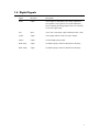
417# 'LJLWDO#6LJQDOV
Signal
Direction
Description
Ready
output
Active High, set immediately after analog outputs have
been updated. This signal will reset itself immediately
prior to updating the analog outputs if not reset externally
via the Ack\ signal input.
Ack\
input
Active low, resets Ready output, minimum width >10ms.
SysErr
output
Active High, indicates 2700 not ready to sample.
Filtrate
output
external sample pump control.
BLK. Pump
output
feed/diluent pump control for Black Probe Chemistry.
WHT. Pump
output
feed/diluent pump control for White Probe Chemistry.
3
51# ,QVWDOODWLRQ
514# 8QSDFNLQJ
Remove the parts from the internal shipping container. Be careful not to discard any parts or supplies.
Check off all items on the Packing List and inspect all assemblies and components for damage. In the
event of damaged or missing parts, contact YSI Technical Support or your Dealer Representative
immediately. Refer to APPENDIX B for phone, fax and address information.
515# ,QVWDOODWLRQ
The YSI 2730 Monitor and Control accessory requires a YSI 2700 SELECT biochemistry analyzer
installed with software version 2.41 or higher for purposes of compatibility. To install the accessory a
small flat-head screwdriver, a #2 Phillips screwdriver, needle-nose pliers and a 5/16″ or small adjustable
wrench are needed. The steps are as follows:
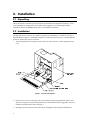
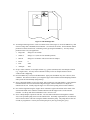
1.
Turn off instrument power using the switch on the rear of the 2700 case. Do not unplug the power
cord.
Figure 1 PC Board Installation
2.
Remove the two screws on the upper rear of the instrument to allow the hinged back panel to open.
Open the rear panel to expose the main printed circuit board and the smaller "piggyback" YSI 2710
turntable controller board as shown in Figure 1.
3.
Discharge any static electricity from your body by touching the YSI 2700 chassis momentarily.
4
4.
Remove the turntable controller board by disconnecting the two cables which plug into it. Disconnect
the cables at the controller board itself, then remove the two mounting screws that hold the board to
the standoffs (hold the standoffs with a wrench or pliers if necessary). Remove the board and place it
aside for a moment.
5.
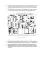
Refer to Figure 2 to help you find the location of the 28 pin EPROM IC U11. Note the orientation of
the IC, specifically the position of the "notch" at the bottom of the part near the battery holder.
J11
J9
Q1
1
D9
RN4
U18
C37
C38
1
U20
U21
R16
U23
C45
R18
C47
C44
C36
C46
R2
C51
C53
U22
U24
R23
C3
R19
D8 C35
R6
C33
C50
C31
D7
R3
1
C49
C48
C43
C2
U26
RN5
R17
U16
R7
R8
R4
D6
C30
R1
R24
R15
R14
D5
D1
D2
D3
D4
F1
RN6
RN3
U15
R29
C28
U14
R27
1
U4
U1
J12
R28
RN1
J8
R26
J10
1
R25
C1
C52
C54
C41
C32
C34
R35
F4
F2
C42
U7
C55
U6
C17
C20
U11
R64
U29
J4
R65
R66
R67
R68
C84
U12
C56
U25
F6
R80
R43
J16
R81
D10
D12
D11
C89
C71
U36
NORM
R52
R45
C90
C70
C57
C69
JB2
J15
D13
D14
C65
F7
D15
D16
R54
C85
R36
C91
C64
D30
R56
PROBE
POL.
BATT
+
A1
X2
D33
C24
JB1
R55
C75
C76
D29
U28
D28
C83
R63
LED
C74 JA1
C23
U31 C81
C80
U32
R77
R78
D32 C88 C82
R49
R50
D23
D21
D24
D27
D26
R75
R74
U27
R76
R62
VIN+
VINGND
VCC2
VEE2
GND
POLB
S1B
S1W
POLW
C15
D25
R72
C72
Q8
D19
U3
RN7
C73
Q7
C60002
060002
R79
C6
1
C68
D/N
P/N
R39
R38
R37
C14 C13
U13
R47
R48
D22
assy.
F5
1
1
U9
R44
C25
C22
J1
TC2 R73
FUSE F2
U5
EPROM
C9
C12
C10
C11
X1
RN2
C5
SW1
C26
R34
U10
Q4
C8
C40
R33
C39
R32
U19
R20
R31
R21
Q3
C19
R30
C29
C27
C16
R53
C7
Q6
U17
U2
J7
Q5
X3
F3
C4
D17
R57
D18
R58
C61
U30
D31
1
R59
D20
FIT RECHARGEABLE BATTERIES ONLY
+5
C66
C77
-7.5
C86
J14
BLACK R61
R60
1
R70
R71
C87
J13
C78
+12
GND
AVEE
GND
AVCC
R69
U35
C67
C79
C58
U34
U33
WHITE
C59
C62
TC3
C63
C60
Figure 2 Eprom Installation
6.
Discharge any static electricity again by touching the YSI 2700 chassis momentarily.
7.
Remove the IC U11 from its socket using a small flat-head screw-driver or pocket knife. Make sure to
place the screwdriver under the IC and not the socket before you start to pry it up. Avoid bending the
pins. Best results are obtained by alternately prying one end of the IC and then the other.
8.
Once the old EPROM has been removed, make sure that all the pins are straight on the new 2730
EPROM and install it in the U11 socket. Make sure that the orientation of the IC (the position of the
notch) agrees with that of the part that was just removed. Once all the pins are aligned, gently press it
into its socket.
5
9.
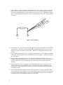
Refer to Figure 2 to help you find the location of the fuse F2. This 1 amp fuse must be removed and
replaced with the 2 amp fuse provided. Carefully remove the old 1 amp fuse by grasping the green
body with your hand and pulling on each end until it comes out of the socket. Install the new 2 amp
fuse by carefully pushing each end into the socket (a small amount at a time) with needle-nose pliers.
See Figure 3.
Figure 3 Fuse Installation
10. Next, discharge any static electricity again, then remove the new YSI 2730 printed circuit board from
its anti-static bag. Install the circuit board where the 2710 turntable board was, as shown in Figure 1,
using the two screws and washers removed earlier. Attach the two ribbon cables in their previous
positions.
11. Using a small adjustable wrench (5/16”, if available) loosen and remove the two locknuts securing the
pump mount side plate from the inside of the instrument as shown in figure 1. Remove the side plate.
Save the locknuts.
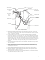
12. Install the Monitor Pump/Solenoid Valve Assembly from the inside by positioning the two studs
through the Pump/Valve Mounting Plate. Be certain that the solenoid valve is above the pump. Refer
to Figure 4. Reuse the two 5/16" locknuts that were removed above and secure the Pump/Valve
Assembly.
13. Plug the Pump Motor lead (six conductor) into the socket marked J4 on the 2730 PC board. (The
connector is keyed for proper installation.) Plug the Solenoid Valve lead (two conductor) into the
socket marked J3. Route the leads in such a way as to avoid any interference when the back plate is
rotated back into place.
14. Next swing open the front panel of the 2700 and remove the side access plate on the left side of the
2700 near the front of the instrument. This is the area through which the 2700 Sipper Tube will move
to reach the External Sample Chamber. Again use a small adjustable wrench (5/16”, if available) to
loosen and remove the two locknuts securing the side access plate.
6
Solenoid Valve
Pump/Valve
Mounting Plate
From Antiseptic
(inner)
From Sample
Source
(outer)
Chamber Outlet
External Sample
Chamber
Monitor Pump
To Waste
Chamber Inlet
Figure 4 Pump Installation
15. Slip the External Sample Chamber assembly over the sheet metal edge of the 2700. Use one of the
5/16" locknuts with the flat washer provided to loosely hold the bracket/chamber assembly in position
for now. See Figure 4 for orientation.
16. Connect the tubing as shown in Figure 4. The 2 inches of small tubing coming from the outside
position of the solenoid valve goes to the sample source. The 2 inches of small tubing from the inside
position of the solenoid valve goes to the antiseptic. Extend these with the silicone tubing provided to
a length that suits your setup. The 6 inches of small tubing coming out of the pump head slips over the
stainless steel chamber inlet. The 6 inches of large tubing coming from the pump slips over the barbed
chamber outlet. The remaining 3 foot length of large tubing goes to a suitable waste container (not
included).
17. Close the rear panel door and replace the two screws which hold it. Be careful not to snag any cables
when closing the door.
18. Install the supplied label on the back of the instrument to indicate that it is equipped with the 2730
hardware. This is intended to prevent others from using the instrument with the turntable (doing so
would damage the 2730 circuits).
19. Install the supplied tubing installation diagram on the side of the 2700 case as shown in Figure 5.
20. Repower the instrument. The printer should print a heading showing 2700 configuration (single or
dual channel) and the new software version (2.81).
21. Next align the Sipper Tube with respect to the 2700 Sample Chamber as you would do in 2700 Setup.
Very likely this has already been done on your unit.
7
Figure 5 Tube Routing Label
22. Activating monitoring software. Refer to Software Flow Chart (Figure 9). Press the MENU key, then
choose 2-Setup, then 3-RunMode, then 4-Monitor. Six selections are shown. Set the Monitor default
parameters to those shown below, confirming each by pressing the ENTER key. You may change
parameters later to fit your application.
•
Purge time
change 0 to 40 seconds.
•
Station #
change 1 to 5 (note #4 is for turntable position)
•
Interval
change 0 to 30 minutes. This is time between samples.
•
Precal
0
•
Flow
2000
•
Antiseptic
YES
23. Set up a waste container, a test sample solution (e.g., glucose standard), and a test antiseptic solution
(e.g., reagent water). You may want to add some food dye to the test sample solution to better
visualize what is happening.
24. Press the MENU key to return to the Main Menu. Again press the MENU key, then 1-Service, then
5-Monitor. This menu level allows you to align the Sipper Tube with the External Sampling Chamber
and to prime the External Pump (Purge Pump).
25. Select 3-External Chamber to move the Sipper Tube to Station #5 (external chamber). Now adjust the
Chamber Bracket forward or backward to align the Sipper, and the Thumb Screw to adjust the
chamber side to side. Visually align the Sipper over the conical opening to the External Chamber.
26. Now test the alignment using the "Sipper down" command. Tighten the locknut on the inside of the
2700 and the thumb screw under the Chamber Bracket while the Sipper Tube is in the External
Chamber. Use the up and down commands to retest. Press 0 to exit.
27. Select 1-Pump Sample to prime the inlet line. The test solution should move through the solenoid
valve to the peristaltic pump, then on to the chamber inlet. Eventually segmented flow (air and fluid)
will be observed in the waste line exiting the chamber toward the pump. The pump shuts off after 40
seconds, as programmed. You may shut off the pump at any time by pressing the [1] key.
8
28. Select 2-Pump Antiseptic to prime the antiseptic line. The test antiseptic solution should move
through the solenoid valve to the peristaltic pump, then on to the chamber inlet. Segmented flow (air
and fluid) will be observed in the waste line exiting the chamber toward the pump. The pump shuts
off after 35 seconds. You may shut off the pump at any time by exiting the Service menu.
29. The Monitor and Control Accessory is now installed. Now configure the 2700 SELECT measurement
and run mode parameters as required for your application. Refer to Section 2 Setup in your 2700
SELECT USER’S MANUAL.
Be sure to re-program all appropriate parameters before using
the 2700.
61# &RQILJXUDWLRQ
614# 0RQLWRU
All monitor parameters are configured through the 2700 software. See Section 5.2 SETUP to configure the
monitor parameters.
615# $QDORJ2&RQWURO
The factory default settings for the Analog Outputs are +5 VDC Full scale for both channels. The default
configuration for the polarity of the Black, White and Filtrate Pump Control Outputs is normal (not
inverted). See the following sections if you have special Analog/Control Output requirements.
3.2.1 Full Scale Voltage
The Digital-to-Analog Converters on the YSI 2730 circuit board may be individually configured to provide
either +5 volts or +10 volts full scale. The JP1 jumper positions 3 through 6 control this parameter.
Positions 3 and 4 affect the white channel output and positions 5 and 6 affect the black channel output.
Figure 6 identifies the parameter controlled at each jumper position.
JUMPER POSITION
1
2
3
4
5
6
JP1 SETTINGS
EFFECT
AUX 10 = RAW 17 VOLTS
AUX 10 = REG 13.0 VOLTS
WHT DAC FULL SCALE = +5V
WHT DAC FULL SCALE = +10V
BLK DAC FULL SCALE = +5V
BLK DAC FULL SCALE = +10V
Figure 6 JP1 Settings
WARNING: Only one jumper per output should be installed!
Installing two jumpers per channel could damage the circuit
components.
9
3.2.2 Full Scale Concentration
The voltage output of the analog interface is scaled relative to the calibration concentration. The user can
configure the analog output for each channel to represent 1, 2, 3, or 4 times the calibration concentration.
These outputs are not configured on the PCB. This configuration option is provided via software in the
setup menu. See Section 5.2.6 ANALOG/CONTROL to set this parameter.
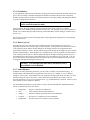
3.2.3 Discrete Output Polarity
Three of the discrete control outputs can be configured to obtain either normal or inverted output. These
three outputs are the Black channel pump control, the White channel pump control and the filtrate pump
control output. Switch SW1 on the 2730 PCB contains four dip switches. Switches 1 through 3 control the
outputs. Switch 4 is not used. Figure 7 depicts the relationship between the switch placement and the
polarity of each output.
SW1 Settings for Output Polarity
Output
Black
Filtrate
White
Not Used
Switch
1
2
3
4
Closed
Inverted
Inverted
Inverted
N/A
Open
Normal
Normal
Normal
N/A
Figure 7 Output Polarity
71# ,QWHUIDFLQJ
714# 6DPSOH#,QWHUIDFH
Several methods exist for obtaining the sample for analysis on the YSI 2700. For discrete sampling the
fixed stations (#2 and #3) may be adequate. In many process monitoring and/or control applications the
sample must be transported (pumped) to the analyzer. When configured appropriately the 2700 SELECT
automatically samples a bioreactor, process stream, or other suitable sample source. Since color, turbidity,
optical density and many other physical factors do not affect the YSI enzyme biosensor, filtration and/or
dilution may not be necessary and the 2700/2730 may draw the sample directly. If cell loss is a concern, or
if high cell density is expected, a filtration device (e.g., tangential flow filter) which separates broth and
cells may be installed between the sample source and the 2730 Monitor and Control accessory.
4.1.1 Filtrate Pump
The filtrate pump control output from the YSI 2730 is provided to control a user-supplied external pump
for pumping the sample from its point of origin to the 2700. The timing of this signal is the same as the
purge pump of the YSI 2730 accessory and is setup inside the "Monitor" part of the RunMode menu. This
option is normally not used since the 2730 monitor pump can transport most samples to the external
chamber. If an external filtrate pump is used, the flow rate must be maintained at or above 570µL/minute
in order to guarantee that the sipper does not aspirate air during the sampling process.
10
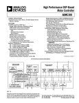
4.1.2 Examples
Monitor Only
Monitor with 2730 Control
Monitor with Computer Control
11
715# (OHFWULFDO#,QWHUIDFH
4.2.1 Analog Outputs
The YSI 2700 analyzer is capable of performing an analysis approximately every two minutes; it is
therefore incapable of producing a truly continuous signal which represents the instantaneous analyte
concentration. It is because of this "semi-continuous" nature of the instrument that the YSI 2730 interface
provides additional signals to aid in synchronizing the reading of the analog outputs. In addition to the two
analog outputs (one output per chemistry, black and white channels), two logical signals are provided.
These "handshake signals" are nominally +5 volts for a logic 1 and ground (0 volts) for a logic 0. The
"READY" signal is output from the YSI 2730 and is set to a logic 1 when the analog output signals have
been updated. This signal indicates to the host system that the analog voltages are "new" and that they
represent the most recent reading of the analyte concentrations. The host system (the external system to
which the YSI 2730 is connected) then can send a logic 0 to the "ACK" input of the YSI 2730. This
"ACK" (acknowledge) signal response from the host resets the READY line of the YSI 2730 to its low
state before the next sample is ready. Figure 8 shows the typical signal pattern that would occur during
two sample update cycles. The READY signal will reset itself immediately prior to updating the analog
outputs if not reset externally via the ACK\ signal input.
A n a lo g O u tp u t
R e a d y
A c k \
Figure 8 Handshake Signals
4.2.2 Pump Control Outputs
Three discrete outputs are provided on the YSI 2730 which are intended to control external pumps. The
means of control is on or off only, no intermediate states are supported. The three outputs are labeled
Black Channel Pump, White Channel Pump and Filtrate Pump. All of these outputs are electrically
identical and are designed as control signals only, i.e. they are incapable of driving any pumps directly.
These signals must be buffered externally in a manner appropriate to the nature of the pumps being used.
These output signals transition between +5 volts and 0 volts nominally. The logic of each, i.e. whether 5
volts turns on or off the external device, is determined by the position of switch SW1 on the 2730 PC board
(See Section 3.2.3). Assuming no inversion enabled by the user, the output turns on the pump with a +5
voltage output, exclusive of any logic inversion imposed by the user supplied buffering circuitry.
12
4.2.3 Auxiliary Connector / Signal List
On the back of the YSI 2700 instrument is the 15 pin "D" type connector labeled "AUXILIARY" where the
2730 signals emanate. The following table relates the signals with the connector pin positions and cable
wire colors.
2730 Signal
Ground
Ground
Ground
Ground
Ground
+5 Volts
White Pump Control
SysErr
White Analog Output
Black Analog Output
Black Pump Control
Filtrate Pump Control
Power Out
Ack\
Ready
Chassis Ground
AUXILIARY pin#
1
2
3
4
5
6
7
8
9
10
11
12
13
14
15
None
Wire color
Black/White
Orange/Black
Blue/Black
Red/White
Black
White
Green/White
Blue/White
Green/Black
Green
Red/Black
Red
Blue
White/Black
Orange
Shield
81# %DVLF#2SHUDWLRQ
IMPORTANT: The following instructions were written assuming a familiarity with the YSI 2700 SELECT
Biochemistry Analyzer. If you ordered the 2700 and 2730 together and are setting up for the first time,
you should refer to the 2700 SELECT USER’S MANUAL for instructions. Once you have successfully
set up and operated the 2700 in the discrete sampling mode, you may proceed with the 2730 Monitor and
Control Accessory installation and setup.
If you are familiar with YSI 2700 SELECT operation, you may proceed with the setup and operation
instructions that follow.
13
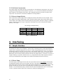
814# 6RIWZDUH
Features specific to the YSI 2730 have been added to the Setup and Service sections of the 2700 menu
structure. Figure 9 shows the new structure with the 2730 features in bold lettering. The following section
briefly describes the 2730 menu options.
Figure 9 Software Flow Chart
14
815# 6HWXS
5.2.1 Monitor
As described in Section 2, Installation, there are six menu selections under Monitor Setup that you must
consider. Briefly, they are:
External Pump Purge Time........Time in seconds required to deliver fresh sample from your source to the
External Sampling Chamber
Station # .....................................Station number where the Sipper Tube will go for a monitor sample,
usually station #5 the external sampling chamber
Interval.......................................Time in minutes between monitor samples
PreCal ........................................Time in minutes before the monitor sample when an autocalibration will
be initiated
Flow ...........................................The flow rate of the monitor pump in uL/min
Antiseptic...................................Antiseptic cycle on or off
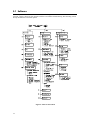
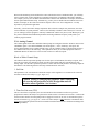
Flow Rate -vs- Purge Time
The flow rate and purge time settings must be such that a sufficient volume of sample is pumped during
each cycle to completely purge the external chamber and system tubing. This is especially important when
an antiseptic is used since the antiseptic may damage the enzyme membrane if aspirated by the sipper
needle. Figure 10 shows the flow rates and minimum time needed to purge the tubing lines from the
solenoid valve to the external sample chamber. These values are based upon a 6-fold volume turnover.
Additional time may be necessary to purge the line from the sample source to the solenoid valve.
Flow Rate
uL/min
100
200
300
400
500
600
700
800
900
1000
1100
1200
1300
Purge Time
Seconds
900
450
300
225
180
150
129
113
101
90
82
75
69
Flow Rate
uL/min
1400
1500
1600
1700
1800
1900
2000
2100
2200
2300
2400
2500
Purge Time
Seconds
65
60
57
53
50
48
45
43
41
39
38
36
Figure 10 Minimum Purge Time
5.2.2 Antiseptic
The antiseptic solution may be defined by the user. Typical solutions might include 1% sodium hydroxide
or 0.25% hypochlorite in reagent water.
15
5.2.3 Sterilization
If your application requires aseptic monitoring, all tubing and connectors should be sterilized (autoclaved)
prior to use. The tubing, connectors and pump head should be assembled, the open ends of the tubing
should be clamped off (two clamps are provided) and the entire assembly (tubing with pump head) should
be sterilized along with the bioreactor.
If the tubing is connected to the bioreactor after sterilization, a
sterile connection must be made.
After sterilization the pump should be remounted onto the 2700. Refer to Section 8.1, Tubing
Replacement, before installing the tubing in the solenoid valve. The antiseptic cycle must be enabled (see
Section 5.2.1) and the antiseptic solution must be primed immediately after the tubing is reconnected (see
Section 5.3.1).
The 2730 may be used for process monitoring and/or control applications without the use of an antiseptic.
Refer to Section 5.2.1.
5.2.4 Make-Up Cycle
The make-up cycle occurs after the 2730 has pumped sample from the sample source for the user
programmed amount of time and the sipper is ready to aspirate. At this point, the solenoid valve switches
to the antiseptic position and the monitor pump flow rate changes from the user programmed rate to
approximately 580µL per minute. This prevents the sipper from drawing all the sample out of the external
chamber and aspirating air. If the antiseptic cycle is disabled by the user, the solenoid valve still switches
to the antiseptic position and air or fluid is pumped through the antiseptic line during the make-up cycle.
The antiseptic line must be kept free from obstructions even if the antiseptic cycle is not used. A dry 0.2
micron filter may be inserted upstream from the solenoid valve to prevent contamination in the air from
entering the antiseptic line during the make-up cycle.
Warning: The antiseptic line must not be blocked off even if
the antiseptic cycle is disabled.
5.2.5 Autocalibration
In addition to setting monitoring parameters, you may want to consider your calibration strategy. In
default settings, autocalibrations are programmed to occur after every 5 samples or every 15 minutes,
whichever occurs sooner. Autocalibrations are also initiated if the temperature drifts more than 1°C in the
chamber housing the enzyme electrodes, or if the calibration current shifts by more than 2% from a
previous calibration, or if one of several sample errors (e.g., unstable baseline) is detected. However, all of
these parameters can be changed or disabled.
The Autocalibration Parameters are listed below. Refer to the YSI 2700 SELECT USER’S MANUAL,
Section 5, Menu Selections for more detail.
16
•
Temperature........Degrees C drift between calibrations
•
Time....................Time in minutes between autocalibrations
•
Sample ................Number of samples performed between autocalibrations
•
Cal Shift..............Precision as % compared to previous calibration
•
Sample Error.......On/Off to detect errors related to system problems
When in the monitoring mode and when the 2700 is stabilized in terms of calibration drift, you will likely
want to change some of these parameters to minimize interference of calibration with monitor sampling.
For example, you may elect to disable autocalibrations related to time and number of samples, then use the
PreCal option under Monitor Setup. Alternatively, you may elect to disable time and calibrate after some
number of samples, or after some fixed time has elapsed. There is no "best configuration". It really
depends on your particular application.
Generally, you will not want to change temperature drift, cal shift or sample error parameters, since these
can be indicators of system problems. However, the flexibility to disable is there and may be exercised. If
you are writing a software program to remotely command the 2700/2730 system (via the RS232 port), you
may want to disable all autocalibration parameters and bring calibration frequency totally under your
software program control.
5.2.6 Analog /Control
The control signals for the white and black channel pumps are configured from the "SETUP" menu via the
"RunMode" option. Once in the RunMode, sub menu option 5, " Aux" (Auxiliary), will expose two
choices, Black channel setup or White channel setup. The two channel setups are identical but specific to
the channel involved (see the following). These parameters allow you to control pumps that will feed
additional nutrients or diluent to a reactor in order to achieve a desired set point.
Black or White Channel Setup
The channel control setup menus prompt users for four pieces of information, the analyte set point, TimePer-Unit error (TPU), the method of control (error direction) and the full scale concentration of each
analog output. The first three parameters pertain to control while the forth pertains to the analog output for
that channel. The following describes the setup considerations for each item.
1. Set Point
This parameter is the concentration at which the analyte will be regulated. It is assumed to be entered in
the units ascribed to the analyte (e.g. g/L, mg/L, etc.).
Caution: Setting or changing this parameter while controlling
will reset the integral portion of the PID algorithm and will
therefore affect regulation. See Section 6.
2. Time-Per-Unit error (TPU)
This is a factor that is computed by the user and entered into the instrument to allow it to perform
proportional control of the analyte in a quasi-static volume such as a fermentor or bioreactor. It reflects the
amount of time that the correction pump must be engaged to correct for an error in concentration equal to
the unit of measure (e.g. g/L, mg/L, etc.). In the case where analyte is added when the concentration falls
below the set point the optimal feed stock concentration and the TPU factor are calculated according to the
following formulae;
17
To calculate the minimum feed stock concentration use the following formula:
Cnc = (SI * Mrc * Vol) / (.8 * SI)
Dlv
Where:
SI = 2700 Sampling Interval in minutes.
Mrc = Maximum rate of change of the analyte concentration in the analyte’s
unit of measure per minute per liter of volume (e.g. g/min/L).
Vol (Average controlled volume of reactor in Liters) = (largest volume + smallest volume)
2
Dlv = feed pump rate of delivery in liters/min.
NOTE: Cnc = correction feed stock concentration in the analyte’s unit of measure.
To calculate TPU use the following formula:
TPU = (1 / Cpdlv) * Vol
Where:
Cpdlv = Correction pump delivery rate in the analyte’s unit of measure per second
(e.g. mg/second, g/second, etc).
Vol (Average controlled volume of reactor in Liters) = (largest volume + smallest volume)
2
NOTE: Time-Per-Unit error in seconds per unit of measure liter (e.g. 50 seconds/gram
liter).
Example:
You are trying to regulate a 5.0 Liter bioreactor at 1.00 g/L glucose concentration. The actual volume of
broth in the reactor is maintained at 3.5 Liters. You know from previous fermentations of that the
maximum consumption rate of glucose is approximately 28.5 g/L/hr. The feed pump delivery rate is 0.1
L/min. The 2700 sampling interval is 5 minutes.
The lowest acceptable concentration of glucose feedstock (Cnc) is calculated as follows:
Sampling Interval = SI = 5 minutes
Maximum rate of change = Mrc = 28.5 g/L/hr = 0.475 g/L/min.
Reaction Volume = Vol = 3.5 Liters
Feed pump delivery rate = Dlv = 0.1 L/min.
Minimum Glucose feedstock concentration = (Cnc)
Cnc = (SI * Mrc * Vol) / (.8 * SI)
Dlv
Cnc = (5 * 0.475 * 3.5) / (0.8 * 5)
0.1
Cnc = 8.3125 / 4.0 = 20.78 g/L glucose
0.1
18
The Time-Per-Unit error (TPU) for this setup is calculated as follows:
Pump rate (in seconds) = (0.1 L/min.) / (60 sec/min.) = 0.00166 L/sec.
Feed Delivery Rate = Cpdlv = 20.78 g/L * 0.00166 L/sec = 0.035 g/sec.
TPU = (1 / Cpdlv) * Vol
TPU = (1 / 0.035) * 3.5
TPU = 101
The TPU parameter has another important function in the 2730 software. PID regulation is enabled
whenever this parameter is not zero (See Section 6). No pump control output will occur if this
parameter is set to zero.
3. Error Direction
This parameter is set to either "under" or "over". Selecting "under" means that the user wishes to regulate
to the set point in an environment where the analyte is being consumed and as such tends to fall under the
set point. In this circumstance the control algorithm will attempt to regulate by making additions of
correction feed stock (which contains the analyte) to the controlled volume. Selecting the "over" error
direction assumes that the correction applied by the controller will have the effect of diluting or removing
analyte to perform regulation.
Example: In the case of a fermentation where glucose is the controlled analyte the user should select the
under error direction since the organisms in the fermentation will consume glucose, thereby forcing the
controller to add glucose via feed stock additions.
4. Analog Output
The voltage output of the analog interface is scaled relative to the calibration concentration. The user can
configure the analog output for each channel to represent 1, 2, 3, or 4 times the calibration concentration.
The output for each chemistry will track sample concentration as long as any chemistry other than "None"
has been selected from the measurement parameters menu. A channel that has been configured as "None"
will remain at 0 volts at the analog output. The analog outputs will change with the sample result for each
channel, black or white, regardless from which station the sample was obtained.
A discrete sample performed at a sample station different than
the monitor station will not affect the analog output.
19
816# 6HUYLFH
5.3.1 Monitor
From the Service Menu option 5, "Monitor", if selected will present three options; 1-Pump Sample,
2-Pump Antiseptic and 3-External Chamber.
Pump Sample
Selecting this option allows the user to prime the sample line.
Pump Antiseptic
This option is used to prime the antiseptic solution.
External Chamber
This option is used to align the external chamber with the sipper needle. When this option is selected, the
sipper will swing out of the 2700 and stop above the external sample chamber. Option 2-Down will allow
the sipper needle to be lowered to test external chamber alignment.
5.3.2 Analog /Control
From the Service Menu option 6. "Analog I/O" if selected will present two options; 1-Analog outputs and
2-Discrete I/O.
Analog Outputs
Selecting this option will allow the user to drive both DAC outputs to full scale (+5 or +10 volts) or to zero
volts with a key press.
Discrete I/O
This option allows the user to toggle the state of each logic output between 0 and +5 volts.
91# 3,'#&RQWURO
The control algorithm incorporated into the 2730 software is a variant of the Proportional-IntegralDerivative (PID) algorithm used in many process controllers today. Because of the many factors which
can affect control it is difficult, if not impossible, to accommodate all circumstances in a single form of the
PID control algorithm. The 2730 control algorithm is no exception. Certain assumptions apply to the
application of this control scheme of which the user should be aware. Deviations from these assumed
conditions will result in degraded regulation.
6.1.1 Assumptions
1.
Regulation is begun (enabled) when the analyte concentration is within ±10% of the set point.
2.
The sampling interval is regular. That is, the period between samples (corrections) is constant.
Random calibration timing will degrade regulation performance if it affects sample timing.
3.
Higher rates-of-change of the analyte are coupled with shorter sampling intervals to the maximum
extent possible.
4.
Maximum control pump on-time is kept less than the sampling interval.
A discrete sample performed at a sample station different than
the monitor station will not initiate regulation or affect analog
output.
20
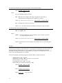
:1# 3ULQWHG#6HWXS#,QIRUPDWLRQ
The following is an example of the Printed Setup Information. See APPENDIX C in the 2700 SELECT
USER’S MANUAL for details on how to get a printout of your setup. The bold type highlights the
Monitor and Analog/Control sections. In the Monitor Section the 2700 is set up to monitor from station #5
(the external chamber) every 3 minutes. The purge time for the pump is 40 seconds, the flow rate is 2000
uL/Minute and no calibration is performed before (precal) the sample. In the Analog/Control Section the
full scale analog voltage of the black and white channels is reached when the sample concentration
measured is 1 times the calibrator value (2.50 g/L in this case). The TPU (Time-Per-Unit-Error) for the
black pump control is 10 seconds per unit of measure (per g/L in this case). The white TPU is 0 (disabled).
The black control set point is 1.00 g/L and the white control set point is 0.
INSTRUMENT SETUP
------------------------------Sample Size
25 uL
SamStation #: 2
CalMethod: One station
BLACK PROBE
Chemistry :
Dextrose
Unit:
g/L
Calibrator:
2.50
Endpoint:
30 Sec
CalStation#: 1
WHITE PROBE
Chemistry : Dextrose
Unit:
g/L
Calibrator:
2.50
Endpoint:
30 Sec
CalStation:
1
AUTOCAL
SampleError: ON
Temperature:
1°C
Time:
15 Min
Sample :
5 Sam
Cal Shift :
2%
RUN MODE
Replicates :
OFF
Sample ID :
OFF
Sip Height : Medium
Autostandby: 2 Hr
MONITOR
MonStation#: 5
SamInterval: 3 Min
Precal :
0 Min
Purge time :
40 Sec
Flow Rate :
2000 uL/Min
Antiseptic :
ON
ANALOG/CONTROL
Black FS
: 1 X CAL
TPU
: 10 Sec
Set
: 1.00
White FS
: 1 X CAL
TPU
: 0 Sec
Set
:0
RS-232
Baud rate
: 9600
Data
: Seven bit
Stop
: One bit
Parity
: Even
Handshake
: RTS/CTS
XON char
: 17
XOFF char
: 19
Mode : Non-multidrop
Address: 38
GENERAL
Radix mark
: "."
Level sensor: OFF
Cal Report
: Brief
SampleReport : Brief
DateFormat
: MM/DD/YY
Software revision: 2.83
YSI 2700D
Wed 08/09/98 11:54:26
---------------------------------
21
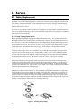
;1# 6HUYLFH
;14# 7XELQJ#5HSODFHPHQW
Replacement of pump tubings, sample and waste line tubings and solenoid valve tubings is applicationdependent. The recommended replacement is 350 hours for the silicone waste tubing and 6 months for all
other tubings, including the PharMed pump tubing, solenoid valve tubing, antiseptic tubing and sample
source tubing. The 2731 Preventive Maintenance Kit provides a complete set of tubings for the YSI 2730
Monitor and Control Accessory.
If you elect to clean tubings, solutions such as 70% isopropanol, 0.5% hypochlorite, and mild detergents in
water are acceptable cleaning agents. Be certain you flush well with water before putting the 2730 Monitor
and Control system back into use.
8.1.1 Pump Tubing Replacement
Before changing pump tubing, first study the tubing connections carefully. The peristaltic pump body is
dual channel and the roller assembly rotates counterclockwise. The inlets for both sample and waste lines
are on the top as you face the mounted pump body. The sample lines and sample pump tubings are nearer
the 2700 SELECT case wall. The waste line is closest to you. The pump waste tubing contains a retainer
(plastic washer) on the inlet (top) side of the pump. The sample pump tubing contains a retainer (plastic
washer) and a plastic tab attached on the inlet (top) side. Refer to Figure 3 for diagrammatic details.
To change pump tubings, remove the two thumb screws securing the pump assembly to the pump motor
sideplate. Next, lower the pump body to a working surface, remove the two O-rings holding the pump
together and separate the two halves of the pump body. Then remove the roller assembly, noting the slot in
one end of the center shaft of the assembly. This slot must engage with the pump motor shaft protruding
through the 2700 SELECT case wall. Be certain to orient the "slot end" correctly on reassembly.
Remove the old tubing, removing tubing retainers as required. The 2731 Preventive Maintenance Kit
contains new retainers and fittings. Clean the inside of the pump housings as needed. A small amount of
lubricant helps to control noise ("squeaks") when the pump rollers are turning. Appropriate lubricant is
provided in the maintenance kit. Using a tissue or swab, lightly coat the inside of the pump body chambers
and rollers with lubricant before installing tubing.
Install the new tubing as shown in Figure 11, Installing Pump Tubing. When installing new pump tubing,
first thread the waste line tubing through one chamber of the pump body. Install the roller assembly (slot
in center shaft oriented up) into the pump body chamber. It will help to twist the roller assembly as you
install it to more easily capture the tubing in between the rollers and chamber wall. Once in place, install
the retainer and adjust the lengths of tubing on each side, locating the retainer on the inlet side of the pump
chamber. You should have about 6 inches (15 cm) on the inlet side.
Figure 11 Installing Pump Tubing
22
Next install a retainer washer on the sample line and insert the tubing through the outer pump chamber
such that the plastic retainer tab and washer will be located on the top when mounted.
Reassemble the 2 pump housings insuring they mate flush. Rotate the halves so that the mounting holes
are aligned. Secure the two pump housings together with the O-rings.
Finally, resecure the pump body assembly to the 2700 sideplate using the two thumb screws.
Reconnect the tubing as shown in Figure 3. Repower the instrument, if necessary. Enter Service mode and
check pump function for proper flow direction. Also listen for any unusual sounds that suggest strain on
the pump motor. This may indicate binding or twisting of the newly installed tubings.
8.1.2 Solenoid Valve Tubing Replacement
Before changing solenoid valve tubing first study the tubing placement carefully. The sample flows
through the outer slot of the solenoid valve and the antiseptic flows through the inner slot (closest to the
instrument case). The sample and antiseptic lines are connected together with a Y-shaped fitting on the
outlet side of the solenoid valve.
To change solenoid valve tubing, grasp the tubing at each end close to the valve and pull it up out of the
slot. Next, disconnect each tubing from the Y-shaped fitting and the inline couplings.
To install the solenoid valve tubing, refer to Figure 4 and the instructions below.
NOTE: The following procedure should be followed when
installing the solenoid tubing to ensure correct valve operation
and prevent premature tubing failure.
1.
From the 2700 main menu press [MENU], 3-DIAGNOSTIC, 2-PUMP then 4-EXTERNAL PUMP.
This will energize the solenoid and engage the pump.
2.
Install the Sample Tubing in the outer solenoid valve slot. Make sure that the tubing lies completely at
the bottom of the slot. Do not stretch the tubing.
3.
Press 4-EXTERNAL PUMP to stop the pump and de-energize the solenoid.
4.
Install the Anti-septic Tubing in the inner solenoid valve slot. Make sure that the tubing lies
completely at the bottom of the slot. Do not stretch the tubing.
NOTE: If the tubing is stretched, the walls may become too thin for the valve to operate properly.
;15# ([WHUQDO#&KDPEHU
There are two approaches to cleaning the external sample chamber.
•
You may use the monitor pump to draw cleaning solution through the system. Reagents such as 70%
isopropanol, 0.5% hypochlorite, and a detergent in warm water are all acceptable cleaning agents. To
clean the "cone" near the tip of the chamber, use a swab or direct a stream of cleaning agent at the area
while the pump is running. Remember, waste must be actively removed from the chamber. Gravity
alone will not insure draining of the chamber.
•
Alternatively, you may disassemble the chamber and clean parts individually. Refer to Figure 15 for
an exploded view of the chamber assembly. There are relatively few parts and no tools are needed.
23
Note: Do not attempt to remove the stainless steel inlet tube. Remember to realign the chamber
(described in Section 2, Installation) before initiating another monitor run.
The chamber body is machined from acetyl copolymer (tradename, Celcon). The outlet fitting is
polypropylene. The hardware parts are all stainless steel. Cleaning the chamber with boiling water and/or
steam sterilization will not harm the chamber parts.
;16# 7URXEOHVKRRWLQJ
This section provides a simple, but systematic, approach to establishing the cause of the most common
monitor station malfunctions. Symptoms related to 2730 Monitor and Control Accessory are somewhat
limited. Most problems will be related to monitor pump function and/or tubing obstructions.
Refer to Section 8 (Troubleshooting) in the 2700 SELECT USER’S MANUAL as an extension of this
troubleshooting section.
Before taking corrective action related to any problem, be certain to collect as much pertinent data as
possible. Try to make use of the 2730 service and diagnostic routines to test potential problem areas.
If you cannot resolve a problem, contact YSI Technical Support for help (See APPENDIX B). When you
communicate with service personnel, please indicate the serial number of the 2700 SELECT and the serial
number of the 2730 Monitor and Control Accessory. Also indicate software revision number, if known. If
you are writing or transmitting a FAX, include a thorough description of the problem. Include printouts in
the "detail" report format, if possible.
24
SYMPTOM
________________________________________________________________
The 2700 SELECT Sipper Tube misses the External Chamber.
POSSIBLE CAUSES: (1) The 2700 SELECT Sipper Tube has become misaligned, possibly through a
physical disturbance or (2) the Station # is assigned to some number other than "5".
CORRECTIVE ACTIONS: (1) Realign the Sipper Tube. Refer to the 2700 SELECT USER’S MANUAL
for instructions. (2) Recheck for the appropriate assignment of the Monitor Station (Section 5.2.1).
SYMPTOM
________________________________________________________________
The 2700 SELECT does not appear to recognize the Monitor Station.
POSSIBLE CAUSE: The 2730 Monitor Pump has not been assigned a purge time.
CORRECTIVE ACTION: Access the 2700 SELECT setup menu and assign a nonzero value to External
Pump Purge Time (Section 5.2.1).
SYMPTOM
________________________________________________________________
The 2730 Monitor (Purge) Pump is running, but no sample flowing.
POSSIBLE CAUSE: There is an obstruction in the sample tubing or external chamber.
CORRECTIVE ACTION: Remove the sample tube connected to the chamber inlet port while the pump is
running. If fluid flows, the obstruction is in the chamber or the waste line. If fluid does not flow, try
"massaging" the tubing to try relieving the blockage. If unsuccessful, begin disconnecting tubing and
forcing air or fluid through with a syringe until you locate the blockage.
SYMPTOM
________________________________________________________________
Bubbles appear at the top of the 2730 External Chamber when the Monitor Pump runs.
POSSIBLE CAUSE: The 2730 Monitor Pump tubing is not configured properly and fluid in the waste line
is trying to flow backwards.
CORRECTIVE ACTION: Check Section 8.1 and correct tubing configuration.
SYMPTOM
________________________________________________________________
Monitor Station results appear to be lower than expected and excess air is observed in the 2700 SELECT
sample chamber.
POSSIBLE CAUSE: The 2700 Sipper Tube is not properly aligned in the vertical plane, i.e., not moving
down far enough into external chamber. Some sample, then air is being aspirated.
CORRECTIVE ACTION: Realign the 2700 Sipper Tube so that the end of the tube appears to extend past
the temperature probe, as viewed through the front of the clear 2700 Sample Chamber. Refer to the 2700
SELECT USER’S MANUAL for Sipper Tube Alignment.
25
SYMPTOM
________________________________________________________________
Fluid leaking; appears to be coming from the Monitor Pump.
POSSIBLE CAUSE: Either the coupling between the sample line and sample pump tubing is leaking or a
pump tubing has failed.
CORRECTIVE ACTION: Locate the leak. If inside the pump, refer to Section 8.1 to replace pump
tubing.
SYMPTOM
________________________________________________________________
Sipper aspirates antiseptic instead of sample (sample results read approximately zero).
POSSIBLE CAUSE: Tubing routed incorrectly in solenoid valve.
CORRECTIVE ACTION: Check tubing routing per Section 8.1.2.
NOTE: Replace membrane if damaged by antiseptic.
FOR PROBLEMS NOT IDENTIFIED IN THE ABOVE CHART CONTACT YSI TECHNICAL
SUPPORT FOR ASSISTANCE. REFER TO APPENDIX B FOR PHONE, FAX AND ADDRESS
INFORMATION.
26
AD1
AD2
AD3
4
6
11
13
15
17
J1
J1
J1
J1
J1
J1
AD6
AD7
RD
21
23
25
1
5
J1
J1
J1
J1
J1
J1
IO/M
9
8
20
18
16
14
12
22
26
24
J1
J1
J1
J1
J1
J1
J1
J1
J1
J1
+
1
+5
DGND
+5
C7
100uF
3
2
5
VOUT
+VIN
8
U1
+5
OSC
2
2
PC5
PC4
PC3
PC2
PC1
PC0
PB7
PB6
PB5
PB4
PB3
PB2
PB1
PB0
PA7
PA6
PA5
PA4
PA3
PA2
PA1
PA0
9
1
NSC810
(20=DGND,40=+5)
T0IN
T0OUT
CE
RD
WR
ALE
IO/M
RESET
AD0
AD1
AD2
AD3
AD4
AD5
AD6
AD7
FB
7
6
1
LP2951
5
2
1
39
38
37
36
35
34
33
32
31
30
29
28
27
26
25
24
23
22
21
8
+5
R
R
1
1
.1uF
C2
W_PUMP
.1uF
C3
C4
17
16
7
8
9
10
11
13
14
15
20
18
19
.1uF
MKUP_CYCLE
ANTI_CYCLE
B_PUMP
1
.1uF
10K
6
RN1
10K
R
R
RN1
1
3.3uF
C5
ANTI_STEP
C1
7
10K
1
10K
R
0.01uF
C6
RN1
R
1
2
RN1
R
5.23K
R2
49.9K
R
1
1
R1
2
SAM_STEP
3
6
8
9
10
11
7
4
12
13
14
15
16
17
18
19
4
GND
SENSE
ERR\ 5VTAP
SD
U4
+ 1
2
2
RESET
WR
ALE
7
10
J1
CE
AD5
19
J1
AD4
AD0
2
AD1
AD0
DB7
DB6
DB5
DB4
DB3
DB2
DB1
DB0
LD\
CS\
WR\
2
DAC B
AD7237
DAC A
AGND
VREF
VOUTB
OFSTB
VOUTA
OFSTA
VDD
4
5
22
24
U2
+17 Volts
SAM_CYCLE
12
DGND
1
3
21
REFINA
REFINB
VDD
VSS
1
6
1
23
J1
6
U3
74HC04
5
6
5
4
3
2
1
JP1
7
8
9
10
11
12
R
R
F_OUT
B_OUT
W_OUT
5
1
10K
RN1
+5
HEADER
6
5
4
3
2
1
VRAW
9
3
1
13
11
U3
74HC04
U3
74HC04
U3
74HC04
U3
74HC04
U3
74HC04
8
4
2
12
10
White DAC output 0 to +5 volts.
White DAC output 0 to +10 volts.
Black DAC output 0 to +5 volts.
Black DAC ouput 0 to +10 volts.
4.
5.
6.
Filtrate Pump
Black Pump
White Pump
SysErr
Ready
Ack \
Black Vout
White Vout
8
6
J2
J2
13 J2
15 J2
14 J2
12 J2
1N914
1N914
VDD
10 J2
Power out = Reg. +12 Volts @ 50 ma.
3.
Power Out
Power out = raw +17 Volts DC.
2.
Effect
1.
Header
1
2
1
2
D3
D1
1
2
1
2
1N914
D4
1N914
D2
4 J2
2 J2
+5
1 J2
3 J2
5 J2
7 J2
9 J2
16 J2
11 J2
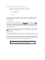
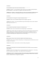
;17# 6FKHPDWLF#'LDJUDP
2
2
2
Figure 12 Schematic 1
27
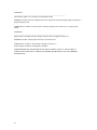
Figure 13 Schematic 2
W_PUMP
B_PUMP
ANTI_STEP
SAM_CYCLE
MKUP_CYCLE
ANTI_CYCLE
SAM_STEP
2
1
2
1
1
2
13
11
9
2
10
SPARE
8
SPARE
12
HC04 SPARE
U7
HC04 SPARE
U7
HC04
U7
HC04
NC
NC
NC
NC
C9
2
1
10K
RN1
15pf
U7
2
3.68MHz
2
10K
RN2
C8
1
10M
R8
3
X1
4
1
25pf
1
1
10K
10K
3
RN2
1
RN2
3
1
5
1
2
3
4
5
6
7
8
9
10
11
12
HC04
U7
4
3
2
1
CLK1
I1
I2
I3
I4
I5
I6
I7
I8
I9
I10
GND
10K
RN1
6
4
3
2
1
2
10
1
5
6
7
8
VCC
IO9
IO8
IO7
IO6
IO5
IO4
IO3
IO2
IO1
IO0
I11
1
+5
SW1
22V10
U6
HC04
U7
SPARE
10K
RN1
.1UF
10K
RN1
2
1
4
C12
.1UF
+5
OSC
BLK INVERT
FIL INVERT
WHT INVERT
+5
DGND
C11
3
24
23
22
21
20
19
18
17
16
15
14
13
4
1
F_OUT
W_OUT
B_OUT
2
PH0
PH1
PH2
PH3
R5
1K
1
9
1
2
3
4
5
6
7
8
U5
VRAW
2
1
ULN2803
I1
I2
I3
I4
I5
I6
I7
I8
GND
O1
O2
O3
O4
O5
O6
O7
O8
VM
.1UF
2
1
R3
10K
R4
3
MJE803
15.0_1W_5%
1
C13
18
17
16
15
14
13
12
11
10
VRAW
2
1
Q1
2
2
1
R6
6.0_5W
6.0_5W
.1uf
C10
1
R7
PH0_OUT
PH1_OUT
PH2_OUT
PH3_OUT
1
2
2
1n4001
D5
+5
1
2
28
NC
SOL_DRV-
SOL_DRV+
J4
J3
J3
J3
SPARE
3
2
1
6 J4
5
J4
J4
4
J4
3
J4
2
1
;18# 3DUWV#/LVW
REF #
PART NO.
DESCRIPTION
N/A
2731
Preventive Maintenance Kit
N/A
110430
PC board assembly
N/A
062428
Fuse, PCB, 2 Amp, 125V, fast act.
N/A
027709
Cable, interface
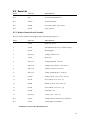
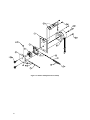
8.5.1 Monitor Pump/Solenoid Assembly
Refer to reference numbers in the diagram on the following page (Figure 14).
REF #
PART NO.
DESCRIPTION
1
110432
Pump assy, Ultem
2
110434
Solenoid/Pinch valve assy. w/bracket, tubing
3
027414
Mounting plate
4
USE 2731
*
5
110433
Motor assy.
6
USE 2731
*
7
USE 2731
*
8
USE 2731
*
9
USE 2731
*
10
002550
*
11
001710
Screw, Mach., 6-32 x .375″ (2)
12
002680
Washer, lock, #8, .328 x .020″ (4)
13
001740
Screw, Mach., 6-32 x .375″ (4)
14
027420
Thumbscrew (2)
15
USE 2731
*
N/A
110439
*
N/A
027423
Clamp, tubing (2) not shown
*
Tubing, solenoid, 1/32″
Tubing, PharMed, .035″ ID
Tubing, waste, silicone, .156″ OD (4’)
Fitting, Y, Kynar, 1/16″ ID (1)
Fitting, straight, Kynar, 1/16″ ID (3)
Washer, Nylon, .141″x .312″x .031″ (2)
O-ring, .301″ x .070″ (2)
Tubing, silicone (.020″ ID x 25′) not shown
Included in 2731 Preventive Maintenance Kit.
29
Figure 14 Monitor Pump/Solenoid Assembly
30
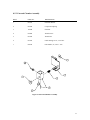
8.5.2 External Chamber Assembly
REF #
PART NO.
DESCRIPTION
1
023013
Chamber Bracket
2
023024
Compression Spring
3
110440
Chamber
4
001008
Thumb Screw
5
061994
Thumb Nut
6
061700
Outlet Fitting, 10-32, 3/32″ hose
7
069818
Flat Washer, #6, .550″ x .031″
Figure 15 External Chamber Assembly
31
<1# $SSHQGL[#$#0#5HTXLUHG#1RWLFH
The Federal Communications Commission defines this product
as a computing device and requires the following notice.
This equipment generates and uses radio frequency energy and if not installed and used properly, may
cause interference to radio and television reception. It has been type tested and found to comply with the
limits for a Class A or Class B computing device in accordance with the specification in Subpart J of Part
15 of FCC Rules, which are designed to provide reasonable protection against such interference in a
residential installation. However, there is no guarantee that interference will not occur in a particular
installation. If this equipment does cause interference to radio or television reception, which can be
determined by turning the equipment off and on, the user is encouraged to try to correct the interference by
one or more of the following measures:
•
Reorient the receiving antenna
•
Relocate the computer with respect to the receiver
•
Move the computer away from the receiver
•
Plug the computer into a different outlet so that the computer and receiver are on different branch
circuits.
If necessary, the user should consult the dealer or an
experienced radio/television technician for additional suggestions.
The user may find the following booklet, prepared by the Federal Communications
Commission, helpful: How to Identify and Resolve Radio-TV Interference
Problems. This booklet is available from the U.S. Government
Printing Office, Washington, D.C. 20402, Stock No.0004-000-00345-4.
32
431# $SSHQGL[#%#0#:DUUDQW\#DQG#6KLSSLQJ
,QIRUPDWLRQ
The YSI Model 2700 Analyzer is warranted for one year from date of purchase by the end user against
defects in materials and workmanship, exclusive of batteries. Within the warranty period, YSI will repair or
replace, at its sole discretion, free of charge, any product that YSI determines to be covered by this
warranty.
To exercise this warranty, write or call your local YSI representative, or contact YSI Customer Service in
Yellow Springs, Ohio. Send the product and proof of purchase, transportation prepaid, to the Authorized
Service Center selected by YSI. Repair or replacement will be made and the product returned, transportation
prepaid. Repaired or replaced products are warranted for the balance of the original warranty period, or at least
90 days from date of repair or replacement.
Limitation of Warranty
This Warranty does not apply to any YSI product damage or failure caused by (i) failure to install, operate
or use the product in accordance with YSI’s written instructions, (ii) abuse or misuse of the product, (iii)
failure to maintain the product in accordance with YSI’s written instructions or standard industry
procedure, (iv) any improper repairs to the product, (v) use by you of defective or improper components or
parts in servicing or repairing the product, or (vi) modification of the product in any way not expressly
authorized by YSI.
THIS WARRANTY IS IN LIEU OF ALL OTHER WARRANTIES, EXPRESSED OR IMPLIED,
INCLUDING ANY WARRANTY OF MERCHANTABILITY OR FITNESS FOR A PARTICULAR
PURPOSE. YSI’s LIABILITY UNDER THIS WARRANTY IS LIMITED TO REPAIR OR
REPLACEMENT OF THE PRODUCT, AND THIS SHALL BE YOUR SOLE AND EXCLUSIVE
REMEDY FOR ANY DEFECTIVE PRODUCT COVERED BY THIS WARRANTY. IN NO EVENT
SHALL YSI BE LIABLE FOR ANY SPECIAL, INDIRECT, INCIDENTAL OR CONSEQUENTIAL
DAMAGES RESULTING FROM ANY DEFECTIVE PRODUCT COVERED BY THIS WARRANTY.
YSI Factory Service Centers
United States
YSI Incorporated • Repair Center • 1725 Brannum Lane • Yellow Springs, OH • 45387 • USA
Phone: 937 767-7241 • Fax: 937 767-9353
Europe
YSI LTD • Lynchford House • Lynchford Lane • Farnborough, Hampshire • GU14 GLT • England
Phone: 441 252 514711 • Fax: 441 252 511855
YSI Authorized Service Centers
California
Fisher Scientific ISD • 2822 Walnut Avenue, Suite E • Tustin, CA • 92681 • Phone: 800 395-5442
Georgia
Fisher Scientific ISD • 2775 Horizon Ridge Court • Suwanee, GA • 30174 • Phone: 800 395-5442
Illinois
Fisher • 1600 West Gleenlake Avenue • Itasca, Ill • 60143 • Phone: 800 395-5442
New Jersey
Fisher Scientific ISD • 52 Fadem Road • Springfield, NJ • 07081 • Phone: 800 395-5442
Pennsylvania
Fisher Scientific ISD • 585 Alpa Drive • Pittsburgh, PA • 15238 • Phone: 800 395-5442
33
4314# &OHDQLQJ#,QVWUXFWLRQV
NOTE: Before they can be serviced, equipment exposed to biological, radioactive, or toxic materials must
be cleaned and disinfected. Biological contamination is presumed for any instrument, probe, or other
device that has been used with body fluids or tissues, or with waste water. Radioactive contamination is
presumed for any instrument, probe or other device that has been used near any radioactive source.
If an instrument, probe, or other part is returned or presented for service without a Cleaning Certificate,
and if in our opinion it represents a potential biological or radioactive hazard, our service personnel reserve
the right to withhold service until appropriate cleaning, decontamination, and certification has been
completed. We will contact the sender for instructions as to the disposition of the equipment. Disposition
costs will be the responsibility of the sender.
When service is required, either at the user's facility or at YSI, the following steps must be taken to insure
the safety of our service personnel.
34
1.
In a manner appropriate to each device, decontaminate all exposed surfaces, including any
containers. 70% isopropyl alcohol or a solution of 1/4 cup bleach to 1 gallon tap water are
suitable for most disinfecting. Instruments used with waste water may be disinfected with .5%
Lysol if this is more convenient to the user.
2.
The user shall take normal precautions to prevent radioactive contamination and must use
appropriate decontamination procedures should exposure occur.
3.
If exposure has occurred, the customer must certify that decontamination has been
accomplished and that no radioactivity is detectable by survey equipment.
4.
Any product being returned to the YSI Repair Center, should be packed securely to prevent
damage.
5.
Cleaning must be completed and certified on any product before returning it to YSI.
4315# 3DFNLQJ#,QVWUXFWLRQV
1.
Clean and decontaminate items to insure the safety of the handler.
2.
Complete and include the Cleaning Certificate.
3.
Place the product in a plastic bag to keep out dirt and packing material.
4.
Use a large carton, preferably the original, and surround the product completely with packing
material.
5.
Insure for the replacement value of the product.
Cleaning Certificate
Organization
Department
Address
City
State
Country
Phone
Model No. of Device
Lot Number
Zip
Contaminant (if known)
Cleaning Agent(s) used
Radioactive Decontamination Certified?
(Answer only if there has been radioactive exposure)
Yes
No
Cleaning Certified By
Name
Date
35
1725 Brannum Lane
Yellow Springs, Ohio 45387 USA
937 767-7241 • 800 765-4974 • Fax 937 767-9353
[email protected] • www.YSI.com
1998 YSI Incorporated
027424
A27424C
May 00