1
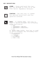
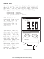
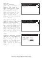
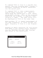
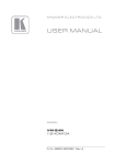
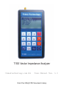
T100 Vector Impedance Analyzer
timestechnology.com.hk
User Manual Ver. 1.1
From The N3UJJ.COM Document Library
T100 is a state of the art portable Vector
Impedance Analyzer. This powerful yet handy
instrument is specifically designed for the
advanced amateur radio experimenters working
at the VHF/UHF band.
TABLE OF CONTENTS
General Description
T100 Menu Structure
Key Definitions
Single Frequency
Sweep Frequency Plot
Calibration
Settings
PC Mode
Firmware Update
Specifications
Accessories
GENERAL DESCRIPTION
The T100 Vector Impedance Analyzer is
essentially a device to inject an RF signal
into whatever is connected to its test port,
and measures the amplitude and phase of the
reflected RF signal.
The reflected amplitude and phase are
calibrated with industrial standard 3-term
Open/Short/Load (OSL) calibration method.
T100 Vector Impedance Analyzer can operate
from 100MHz to 170MHz (VHF), and from 400MHz
to 470MHz (UHF), with a 25KHz minimum step
size.
From The N3UJJ.COM Document Library
T100 MENU STRUCTURE
MAIN MENU
SINGLE FREQ
•SWR
•IMPEDANCE (SERIAL)
•IMPEDANCE (PARALLEL)
•S11 (RECTANGULAR & POLAR)
SWEEP FREQ PLOT
SWR
IMPEDANCE
(Z)
RESISTANCE (R)
REACTANCE
(X)
RETURN LOSS (S11)
PHASE ANGLE
CALIBRATE
CONNECT OPEN
CONNECT SHORT
CONNECT LOAD
SETTINGS
BACKLIGHT
AUTO
ON
OFF
AUTO POWER OFF
ENABLE
DISABLE
BATTERY
ALKALINE
NIMH
CAL DATA PROTECT
LOCK CAL DATA
UNLOCK CAL DATA
INFO
PC MODE
From The N3UJJ.COM Document Library
KEY DEFINITIONS
POWER : Press and hold this key
for two seconds to turn on or off
T100 Vector Impedance Analyzer.
CONFIRM : Use this key to confirm
the desired selections and frequencies entered.
MODE : In SINGLE FREQ, this key is
used to switch between the following
modes cyclically:
• SWR
• IMPEDANCE (SERIAL)
• IMPEDANCE (PARALLEL)
• S11
In SWEEP FREQ PLOTS, this key is used
to switch between the following functions cyclically:
• FREQUENCY
• Y SCALE
• ALIGNMENT
• STEP SIZE
From The N3UJJ.COM Document Library
ARROWS : These keys are used to select the desired menu items or options. They are also used to increase/decrease the frequency. Hold
to increase/decrease frequency automatically. In SINGLE FREQ, the step
size is fixed at 25KHz. In SWEEP
FREQ PLOT, the current step size can
be selected with the MODE key.
0~9
NUMERIC : Use these keys to enter
the desired frequency directly.
Frequencies within the valid operating range will automatically be
aligned to the 25KHz steps. Frequencies outside the valid operating range will be ignored.
BACK : Cancel the current operation and/or go back to the previous menu.
From The N3UJJ.COM Document Library
SINGLE FREQ
In this mode, T100 can display the measured
data in any of the following four representations. You may switch cyclically through
these representations with the MODE key.
•SWR
•IMPEDANCE (SERIAL)
•IMPEDANCE (PARALLEL)
•S11 (RECTANGULAR & POLAR)
SWR displays the
Standing Wave Ratio
in large font for
easy reading. It
also displays the
impedance (Z) for
reference.
IMPEDANCE (SERIAL)
displays the impedance seen from the
test port. The impedance is resolved
into the real (resistive) part and
imaginary (reactive)
part connected in
series. The corresponding inductance
or capacitance is
also displayed according to the sign
of the reactance.
SWR
FREQ:435025
Z=138.08
IMPEDANCE
FREQ:435025
101.80 - j112.58
3.25pF
SERIAL
From The N3UJJ.COM Document Library
IMPEDANCE (PARALLEL)
displays the impedance
seen from the test
port. The impedance
is resolved into the
real (resistive) part
and imaginary (reactive) part connected
in parallel. The corresponding inductance
or capacitance is also
displayed according to
the sign of the reactance.
S11 displays the
rectangular and
polar representations of the S11
measured.
IMPEDANCE
FREQ:435025
240.10 - j194.53
1.88pF
PARALLEL
S11
FREQ:435025
RECTANGULAR:
0.58 + j0.34
POLAR:
|0.67| <-30.10
From The N3UJJ.COM Document Library
SWEEP FREQ PLOT
Under this menu, T100 can plot any of the following measured data over the desired frequency range:
•SWR
•IMPEDANCE
•RESISTANCE
•REACTANCE
•RETURN LOSS
•PHASE ANGLE
(Z)
(R)
(X)
(S11)
Use the MODE key to switch cyclically between
any of the following parameters to change
their value.
•FREQUENCY - use the ARROW keys to increment
or decrement the frequency by the value of
STEP SIZE. The cursor on the plot will move
accordingly. The frequency can also be entered directly using the numeric keys.
•Y SCALE - use the ARROW keys to select the
maximum value on the Y axis. Possible values
are 3, 10, 30, 100, 300, and 1000.
•ALIGNMENT - use the ARROW keys to select
if the directly entered frequency should be
aligned to the CURRENT position of the cursor,
BEGIN (leftmost on the plot), CENTER (of the
plot), or END (rightmost of the plot). Ranges
outside the valid frequencies will be shaded.
•STEP SIZE - use the ARROW keys to select
the desired frequency step size. Possible
values are 25KHz, 100KHz, 500KHz,and 1MHz.
From The N3UJJ.COM Document Library
CALIBRATION
T100 Vector Impedance Analyzer employs industrial standard Open/Short/Load (OSL) calibration method to eliminate various system
errors. To perform accurate measurements,
T100 needs to be calibrated against the OPEN,
SHORT, and LOAD standards. Three high quality OPEN, SHORT, and LOAD SMA terminators are
included for this purpose. Resulting calibration data to be used in computations will be
stored in non-volatile memory in T100.
Calibration data is
CALIBRATE
locked upon power up
of T100 to avoid acDATA LOCKED
cidental erasure. It
GOTO SETTINGS MENU
has to be unlocked in
TO UNLOCK DATA FIRST
the SETTINGS menu,
before CALIBRATION can
be performed.
Connect securely the
OPEN standard, and
then press the OK key
to start calibration.
Likewise for the SHORT
and LOAD standards in
sequence to complete
the calibration.
Calibration data will
be locked again automatically after calibration. The instrument is now ready to
use. If desired, T100
can be re-calibrated
at any time.
CALIBRATE
CONNECT OPEN
CALIBRATE
CALIBRATION DONE
From The N3UJJ.COM Document Library
SETTINGS
A number of general
options and information are available in
this menu.
BACKLIGHT
AUTO - Turn off
backlight automatically if no key
is pressed for 30
seconds.
ON - Leave backlight
always on
OFF - Leave backlight always off
AUTO POWER OFF
ENABLE - Automatic
power off if no
key is pressed for
5 minutes.
DISABLE - No automatic power off.
SETTING MENU
BACKLIGHT
AUTO POWER OFF
BATTERY
CAL DATA PROTECT
INFO
BACKLIGHT MENU
AUTO
ON
OFF
AUTO POWER OFF MENU
ENABLE
DISABLE
From The N3UJJ.COM Document Library
BATTERY
Choose between
ALKALINE and NIMH to
reflect the type of
batteries being used.
It only affects the
threshold voltage
dictating when a low
battery sign on the
upper right hand
corner of the display
will appear.
CAL DATA PROTECT
Select UNLOCK CAL DATA
before calibration.
Calibration data will
be locked automatically after calibration.
Alternatively, choose
LOCK CAL DATA to lock
calibration data manually if necessary.
INFO
Display general information of the device,
as well as the battery voltage. ( 5
blocks on the battery
bar as battery full
and 1 block as battery
empty.)
BATTERY MENU
ALKALINE
DISABLE
PROTECT MENU
LOCK CAL DATA
UNLOCK CAL DATA
SYSTEM INFORMATION
MODEL : T100
H/W VER: 1.00
F/W/VER: 1.00
BATTERY:
From The N3UJJ.COM Document Library
PC MODE
T100 is capable of communicating with a
PC via an emulated serial link over the
USB connection. Virtual serial port
driver for Windows XP is included in the
T100 CD-ROM and should be installed before connecting your T100 to a PC. A
sample host program for Windows XP is
also included to demonstrate controlling
T100 from a PC, and displaying T100 measured data.
The (virtual) serial communication between T100 and the PC should be configured
as follows:
Baud Rate = 38400 baud
Parity Bit = None
Data Bits = 8
Stop Bit = 1
On entering the PC MODE, T100 will display the “WAITING FOR HOST CMD” message
and listen to the serial port.
PC MODE
WAITING FOR HOST CMD
From The N3UJJ.COM Document Library
To command T100 to tune to a specific frequency, the host program shall transmit a
six-digit frequency in ASCII characters
via the serial port.
To command T100 to take a measurement,
send an ASCII character ‘S’. Then receive from the serial port a null terminated ASCII string. This is the measured
magnitude and argument in degrees, separated by a comma.
The same result will
be displayed on T100 at the same time.
Send another ‘S’ to repeat measurement at
the same frequency, or issue another six
digit frequency to tune to a new frequency.
Sending an ASCII character ‘D’ will bring
T100 back to the initial state, displaying the “WAITING FOR HOST CMD” message
and listen to the serial port.
PC MODE
FREQ : 144000
|S11|
0.9577
<S11
-14.72
From The N3UJJ.COM Document Library
FIRMWARE UPDATE
T100 firmware can be updated as new releases
are available. Updated firmware file can be
downloaded from the Internet to a PC and
programmed to the T100 via the USB interface.
Caution
1. Please use fresh batteries
when updating firmware.
2. Do not turn power off or remove batteries during firmware
updating.
Firmware Update
Hold down the “Mode”
key while switching
on T100 to enter the
“Firmware Update”
Mode. T100 will show
the screen on the
left.
On a PC running Windows XP operating system,
open a DOS console in a directory with the two
files update.exe and firmware.ENC.
Plug in the USB cable to connect the PC and
T100. Find out which USB emulated COM port
T100 is connected to from the Control Panel/
System/Hardware/Device Manager on the PC.
With T100 at “Firmware Update” mode, issue the
following command in the DOS console to update
the firmware with the file firmware.ENC :
update firmware.ENC -COMx -38400
From The N3UJJ.COM Document Library
T100 SPECIFICATIONS
Frequency Range: 100MHz ~ 170MHz (VHF)
400MHz ~ 470MHz (UHF)
PLL Synthesized
Frequency Resolution : 25KHz
Test Port Connector : SMA
Output Power : > 0dBm (typical)
Harmonics : < -30dB (minimum)
Display :
128 x 64 dots graphical LCD with backlight
Physical Dimensions :
140mm(length) x 68mm(width) x 25mm(thick)
Net Weight : 130 gram (without batteries)
Power : AA Size Battery x 2
ACCESSORIES
SMA connector for OPEN Calibration: P/N 202112
SMA connector for SHORT Calibration:P/N 132331
SMA connector for LOAD Calibration: P/N 132360
SMA male to BNC female adaptor
SMA male to SO-239 adaptor
USB A to mini-B cable
CD-ROM
From The N3UJJ.COM Document Library