1
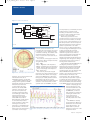
12_13_14_radcom_jul07
13/6/07
14:56
Page 12
PRODUCT REVIEW
CHRIS LOREK
PO BOX 400, EASTLEIGH,
HAMPSHIRE SO53 4ZF
G4HCL
EMAIL [email protected]
AIM4170
Antenna Analyser
Chris Lorek falls in love with this versatile PC-based instrument
12
Photo 1:The AIM4120 is a compact size
Photo 2: Rear panel connections for DC power and
RS-232
BACKGROUND. When I first started the
hobby many years ago, I realised that an
essential accessory to my shack was most
certainly an SWR meter. This allowed me
to keep an eye open for antenna problems
as well as making sure my transmitter was
given a good match to my antenna system.
I still have that same meter now, tens of
years later, and I still wouldn’t be without
one. When I started a new job around 18
years ago I was introduced to using a
Hewlett Packard RF Network Analyser,
costing over £30,000, to perform antenna
systems tests with. How I wish I’d have
been able to use one earlier, especially
during the time I worked hard to invent an
electronic automatic antenna tuning unit.
What had taken me a significant time for a
simple impedance measurement would
have taken less than a minute, so that I
could really see what my antenna system
was doing. But haven’t times moved on
since then! As soon as I saw the AIM4120,
I was immediately interested and I was
pleased to be able to test one.
kHz and 170 MHz. The accompanying PC
control program calculates the actual
displayed parameters such as an SWR
graph, Smith Chart etc, and plots the
results onto screen in ‘real time’ either as a
single sweep or as a continuous
measurement. Results of each sweep can
of course be saved for subsequent analysis
and to compare results. Although most
amateurs will use a nominal 50 ohms
antenna and coax impedance, the analyser
can make measurements up to 10 kilohms
with ‘true’ measurements of inductive and
capacitive reactance. You could thus use it
to measure the resistance and reactance of
discrete components such as capacitors
and coils for homebrew projects.
As well as measuring these parameters
at the physical point of the coax connector
on the unit, a quick ‘calibration’ procedure
can be performed with an open, short, and
known resistive load, each at the end of
any length of coax cable you’re using; these
terminations are usefully provided with the
analyser. With this, the coax is ‘normalised’
out and your measurements are that of the
actual antenna system itself which is
connected to the end of your coax. It can
also detect whether you have a cable fault,
such as an open or short some way along
the length, as well as the actual cable loss
etc. If you can’t get to the end of your coax
easily, for example if it’s up a fixed mast or
FEATURES. The AIM4170 antenna
analyzer uses a small box containing the
actual hardware, together with your shack
or laptop PC for the ‘user interface’. The
system is designed to measure complex
impedance (ie both magnitude and phase)
across any selected range between 100
tower, you can use the analyser to detect
the electrical length of the coax from a
phase measurement and use this instead,
or indeed you can enter the coax length
plus the velocity factor from
manufacturer’s figures.
In a nutshell, the analyser can measure
and display in a linear/log graph or Smith
Chart format:
•SWR referenced to any impedance
•Resistance and reactance at the cable
input
•Resistance and reactance at the antenna
terminals
•Resistance and reactance of discrete
components
•Return loss
•Reflection coefficient
•Cable length
•Cable impedance
•Cable loss
•Distance to coax fault (open or short)
•Component and quartz crystal
parameters
CIRCUITRY. Inside the unit, two digital
synthesisers are used to generate the
required test frequencies, along with
bandpass filters to reduce the effects of
external signals such as strong local RF
signals from other transmitters which could
corrupt your readings. A 12 bit analogue to
digital converter is used rather than a
simple diode detector, which gives far
better linearity for more accurate
measurements. Most SWR meters just use
diodes. The internal RF generator can also
be used as a local signal source, for
example to check your receiver.
SIZE. The unit itself is compact, measuring
127 W x 40 H x 108mm D. A handy ‘quick
start’ guide is provided along with a CD
containing the complete user manual in pdf
format, the operating program, and other
files such as configuration data and a help
file, Also supplied is a ready-made RS-232
lead and a set of small calibration loads
terminated in suitable BNC connectors. A
BNC to SO-239 coax adapter is also
provided so that you can connect a coax
terminated in a PL-259 plug to the unit.
POWER. The AIM4170 is powered from a
6-15V DC supply. A rear panel socket is
provided for an external supply. There’s
RadCom ♦ July 2007
12_13_14_radcom_jul07
13/6/07
14:56
also enough room inside the unit if you
want to fit a 9V PP3 sized battery. A diode
circuit is fitted within the circuitry so that
an external supply and any internal battery
won’t interfere with each other. The unit
consumes around 50mA when switched
on and around 250mA when a
measurement is in progress. With the unit
switched off, the current drawn is less than
a microamp, and an ‘auto power off’ mode
is available which can switch the unit off
after 10 minutes of no commands being
received from a PC.
IN USE. Units sold in the US come with a
plug-in 110V AC to 12V DC wall supply,
but many amateurs will already have a
suitable 12V DC source in their shack.
Having plugged in a suitable lead and
connected up, I then just copied the files
from the CD onto a sub-directory on my PC
and clicked on the AIM_562.exe program,
Page 13
which set the system running. Then,
with the RS-232 lead connected
between the analyser and my PC, I just
selected the correct comm port for my
PC and I was in business. What could
be simpler? If your PC doesn’t have any
RS-232 ports then you’ll need to use
an in-line RS-232 to USB adapter. I’m
told that current releases of the
program, version 564 onwards, have a
“Find comm port” function to
automatically scan for the correct port
which makes things even easier. The
system can itself be run from just the
CD if you wish, eg for use round at a
friend’s shack. It’s only when in
‘calibrate’ mode that files need to be
written to the program directory (or
even just a floppy disk if your PC
accepts one). The latest software
version (including user manual), which can
be used in demo mode without the
Photo 3: Inside the unit, a well-built layout with room
for an internal battery
7
0
0
2
C
F
H
RS
GB
!
t
n
ve 2007
E
er
b
A
o
IOT th Oct
14
&
h
F 2t
r Hshire
e
i
em rd
r
dfo
P
e
B
ds re,
rl s Cent
o
W
ke
a
e
L
h
T
ton
s
o
b
Wy
E
U
N
E
V
NEW
&
ME RS
O
C
E
L
WE DINN5.00
2
X
D
M£
FRO
OK
BONLINE
O DAY
TO
1
res
ectu ures
L
n
ct tures
io
l Le
edit
c
z
DXp nationa ical Le 50MH
r
n
e
h
t
z
c
H
In
e
36k
or T
CH.
Maj ands 1
U
M
B
E ..
H,
All
M
C
LOW
MUTO CO
CES
I
D
R
P R NGS
AN RE
9
737
MO
FO OKI RE
04
9
70
BOEFO UG
. 08
L
E
T
B th A
ION
fc
h
MAT
/
14
R
O
g
E
r
NF
IN
o
b.
g
s
.r
ww :
L
EI
OR OK ON
M
R
O
B
O
F TO
OR
w
sors
pon
or S
Maj
12_13_14_radcom_jul07
13/6/07
14:56
Page 14
PRODUCT REVIEW
Figure 1: 2m antenna array VSWR plot
FIGURE 1
Fout
DDS
AD9859
0.1–170MHz
Low Pass
Filter
ANT
Mixer
NE612
XTAL OSC
20MHz
AMP
and stop frequency, or individual pre-stored
amateur bands, to measure across.
1KHz
Following a measurement I could store
Low Pass
DDS
Filter
AD9859
scan files as well as simply print out the
AMP
ANALOG
Mixer
scan onto a connected printer.
NE612
CPU
MSP430
Beside using my mouse to select
DIGITAL
operational modes, several one-touch ‘hot
key’ functions were available, for example
to scan, rescan, enter new limits and so on.
RS232
PC
One handy function I used the analyser for
during the review period was to make up a
© RADCOM
number of quarter-wave coax ‘stubs’.
These I’d use in line with my VHF system
term use, I stored the antenna coax
to notch out pager breakthrough on receive
parameters for each system to disc so that
as well as reducing the level of 6m
I could ‘keep an eye’ on what the ravages
transmitter 2nd harmonics. Living in a
of weather could bring; the software could
rather RF congested area as well as a
usefully superimpose either repeated
planned ‘housing estate’ village with over
scans, or a scan and a stored scan file, for
100 amateurs within a mile radius, I
me to compare.
quickly found myself popular with several
For each scan, various graph colours are
neighbouring radio colleagues in offering a
used for traces, which correspond to those
measurement service for their needs as
along the vertical axis:
well as general measurements!
I was impressed with the AIM4170, and
•Red – SWR
checking the performance against a
•Green – Magnitude of the Impedance
•Orange – Resistive Part of the Impedance hardware-based laboratory calibrated RF
network analyser showed no discernible
•Yellow – Reactive Part of the Impedance
difference in measurements across the
•Violet – Phase Angle of the Impedance
operational range. The only difference was
•Blue – Return Loss
that the AIM4170 was rather more
As I moved my PC mouse along the
Figure 2: 80m / 40m trapped dipole Smith Chart Plot
graph scale, the actual parameter values of portable, especially when operated from an
internal battery and linked to a selfeach of these were shown on the display,
powered laptop. Also, the other (rather
eg the exact SWR figure etc, rather than
hardware, can be downloaded from the
more expensive) analyser when coupled to
having to try to visually read this from the
manufacturer’s web site at
an external HF antenna system showed
graph display. The data can even be
www.w5big.com/prog_update.htm.
plenty of ‘blips’ from off-air signals, usually
sounded out in Morse for visually-impaired
I started with a simple check of my
above around 6MHz, whereas the filtering
amateurs. I could select either an entire
existing antenna systems for VSWR,
in the AIM4170 in the same measurement
spectrum such as 1.8-30MHz, any start
although the analyser also showed me
situation completely got rid of
where the actual resonance
these and thus gave a more
occurred, which was often
accurate measurement. I was
different to the lowest SWR!
very happy indeed in using
Using this, I managed to ‘fine
the AIM4170, so much so
tune’ some of my antennas,
that I purchased it at full price
including my multi-band three
following the review for the
element HF yagi of which I had
use of myself and my
originally tuned the traps,
colleagues at my place of
several years ago, simply for
work for portable and off-site
lowest SWR on each band.
use.
Resonating this correctly should
The AIM427 is currently
of course have improved the
priced at £279 inc VAT and is
front to back ratio as well as the
distributed in the UK and Eire
forward gain and side lobe
by Vine Antennas Ltd., Tel
performance, a worthwhile time
01691 831111, who our
spent! Likewise on 2m and 6m,
where I found my antennas were Figure 3: 80m / 40m trapped dipole VSWR plot, the coax length effects can easily be thanks go to for the loan of the
analyzer for review.
each a little ‘out’. For longer
seen
Fout + 1KHz
14
RadCom ♦ July 2007