1
Motion Control System
and
Operator Interface* (VC1)
User Manual
Revision 1.9
January 2006
PAN CONTROLS LIMITED
( * ) Optional keypad and display
Revision 1.9
VC1 Controller User Manual
Table of Contents
1
DOCUMENT MANAGEMENT . . . . . . . . . . . . . . . .
1.1 Release . . . . . . . . . . . . . . . . . . . . . . . . . . . . .
1.2 Critical changes to software . . . . . . . . . . . . . .
1.2.1
Version 107.6 (October 1999) .
1.2.2
Version 107.8 (February 2000)
1.2.3
Version 108.0 (March 2000) . . .
1.2.4
Version 109.7 (August 2003) . .
1.3 Key additions to software . . . . . . . . . . . . . . . .
1.3.1
Version 106.6 . . . . . . . . . . . . . .
1.3.2
Version 106.7 . . . . . . . . . . . . . .
1.3.3
Version 106.8 . . . . . . . . . . . . . .
1.3.4
Version 106.9 . . . . . . . . . . . . . .
1.3.5
Version 107.0 . . . . . . . . . . . . . .
1.3.6
Version 107.1 . . . . . . . . . . . . . .
1.3.7
Version 107.2 . . . . . . . . . . . . . .
1.3.8
Version 107.3 . . . . . . . . . . . . . .
1.3.9
Version 107.4 . . . . . . . . . . . . . .
1.3.10
Version 107.5 . . . . . . . . . . . . . .
1.3.11
Version 107.6 . . . . . . . . . . . . . .
1.3.12
Version 107.7 . . . . . . . . . . . . . .
1.3.13
Version 107.8 . . . . . . . . . . . . . .
1.3.14
Version 107.9 . . . . . . . . . . . . . .
1.3.15
Version 108.0 . . . . . . . . . . . . . .
1.3.16
Version 108.1 . . . . . . . . . . . . . .
1.3.17
Version 109.0 . . . . . . . . . . . . . .
1.3.18
Version 109.1 . . . . . . . . . . . . . .
1.3.19
Version 109.2 . . . . . . . . . . . . . .
1.3.20
Version 109.3 . . . . . . . . . . . . . .
1.3.21
Version 109.4 . . . . . . . . . . . . . .
1.3.22
Version 109.5 . . . . . . . . . . . . . .
1.3.23
Version 109.6 . . . . . . . . . . . . . .
1.3.24
Version 109.7 . . . . . . . . . . . . . .
2
INTRODUCTION . . . . . . . . . . . . . . . . . . . . . . . . . . . . . . . . . . . . . . . . . . . . . . . . . . . . . . . . . . . . . Page 4
3
SYSTEM OVERVIEW . . . . . . . . . . . . . . . . . . . . . . . .
3.1 Circuit boards . . . . . . . . . . . . . . . . . . . . . . . . . . .
3.1.1
Control board (PC3/120) . . . . . . .
3.1.2
Control daughter board (PC3/121)
4
GENERAL DESCRIPTION - CONTROLLER . . . . . . . . . . . . . . . . . . . . . . . . . . . . . . . . . . . . . . . . Page 6
5
GENERAL DESCRIPTION - SOFTW ARE FUNCTIONALITY . . . . . . . . . . . . . . . . . . . . . . . . . . . Page 8
6
MODIFICATIONS TO THE USER PROGRAMME . . . . . . . . . . . . . . . . . . . . . . . . . . . . . . . . . . . . Page 9
7
COMMAND DESCRIPTION . . . . . . . . . . . . . .
7.1 General . . . . . . . . . . . . . . . . . . . . . . . . . .
7.2 Command Reference . . . . . . . . . . . . . . .
7.2.1
Miscellaneous commands
7.2.2
Mode commands . . . . . . .
7.2.3
Move commands . . . . . . .
Copyright © 2006 Pan Controls Limited
.
.
.
.
.
.
.
.
.
.
.
.
.
.
.
.
.
.
.
.
.
.
.
.
.
.
.
.
.
.
.
.
.
.
.
.
.
.
.
.
.
.
.
.
.
.
.
.
.
.
.
.
.
.
.
.
.
.
.
.
.
.
.
.
.
.
.
.
.
.
.
.
.
.
.
.
.
.
.
.
.
.
.
.
.
.
.
.
.
.
.
.
.
.
.
.
.
.
.
.
.
.
.
.
.
.
.
.
.
.
.
.
.
.
.
.
.
.
.
.
.
.
.
.
.
.
.
.
.
.
.
.
.
.
.
.
.
.
.
.
.
.
.
.
.
.
.
.
.
.
.
.
.
.
.
.
.
.
.
.
.
.
.
.
.
.
.
.
.
.
.
.
.
.
.
.
.
.
.
.
.
.
.
.
.
.
.
.
.
.
.
.
.
.
.
.
.
.
.
.
.
.
.
.
.
.
.
.
.
.
.
.
.
.
.
.
.
.
.
.
.
.
.
.
.
.
.
.
.
.
.
.
.
.
.
.
.
.
.
.
.
.
.
.
.
.
.
.
.
.
.
.
.
.
.
.
.
.
.
.
.
.
.
.
.
.
.
.
.
.
.
.
.
.
.
.
.
.
.
.
.
.
.
.
.
.
.
.
.
.
.
.
.
.
.
.
.
.
.
.
.
.
.
.
.
.
.
.
.
.
.
.
.
.
.
.
.
.
.
.
.
.
.
.
.
.
.
.
.
.
.
.
.
.
.
.
.
.
.
.
.
.
.
.
.
.
.
.
.
.
.
.
.
.
.
.
.
.
.
.
.
.
.
.
.
.
.
.
.
.
.
.
.
.
.
.
.
.
.
.
.
.
.
.
.
.
.
.
.
.
.
.
.
.
.
.
.
.
.
.
.
.
.
.
.
.
.
.
.
.
.
.
.
.
.
.
.
.
.
.
.
.
.
.
.
.
.
.
.
.
.
.
.
.
.
.
.
.
.
.
.
.
.
.
.
.
.
.
.
.
.
.
.
.
.
.
.
.
.
.
.
.
.
.
.
.
.
.
.
.
.
.
.
.
.
.
.
.
.
.
.
.
.
.
.
.
.
.
.
.
.
.
.
.
.
.
.
.
.
.
.
.
.
.
.
.
.
.
.
.
.
.
.
.
.
.
.
.
.
.
.
.
.
.
.
.
.
.
.
.
.
.
.
.
.
.
.
.
.
.
.
.
.
.
.
.
.
.
.
.
.
.
.
.
.
.
.
.
.
.
.
.
.
.
.
.
.
.
.
.
.
.
.
.
.
.
.
.
.
.
.
.
.
.
.
.
.
.
.
.
.
.
.
.
.
.
.
.
.
.
.
.
.
.
.
.
.
.
.
.
.
.
.
.
.
.
.
.
.
.
.
.
.
.
.
.
.
.
.
.
.
.
.
.
.
.
.
.
.
.
.
.
.
.
.
.
.
.
.
.
.
.
.
.
.
.
.
.
.
.
.
.
.
.
.
.
.
.
.
.
.
.
.
.
.
.
.
.
.
.
.
.
.
.
.
.
.
.
.
.
.
.
.
.
.
.
.
.
.
.
.
.
.
.
.
.
.
.
.
.
.
.
.
.
.
.
.
.
.
.
.
.
.
.
.
.
.
.
.
.
.
.
.
.
.
.
.
.
.
.
.
.
.
.
.
.
.
.
.
.
.
.
.
.
.
.
.
.
.
.
.
.
.
.
.
.
.
.
.
.
.
.
.
.
.
.
.
.
.
.
.
.
.
.
.
.
.
.
.
.
.
.
.
.
.
.
.
.
.
.
.
.
.
.
.
.
.
.
.
.
.
.
.
.
.
.
.
.
.
.
.
.
.
.
.
.
.
.
.
.
.
.
.
.
.
.
.
.
.
.
.
.
.
.
.
.
.
.
.
.
.
.
.
.
.
.
.
.
.
.
.
.
.
.
.
.
.
.
.
.
.
.
.
.
.
.
.
.
.
.
.
.
.
.
.
.
.
.
.
.
.
.
.
.
.
.
.
.
.
.
.
.
.
.
.
.
.
.
.
.
.
.
.
.
.
.
.
.
.
.
.
.
.
.
.
.
.
.
.
.
.
.
.
.
.
.
.
.
.
.
.
.
.
.
.
.
.
.
.
.
.
.
.
.
.
.
.
.
.
.
.
.
.
.
.
.
.
.
.
.
.
.
.
.
.
.
.
.
.
.
.
.
.
.
.
.
.
.
.
.
.
.
.
.
.
.
.
.
.
.
.
.
.
.
.
.
.
.
.
.
.
.
.
.
.
.
.
.
.
.
.
.
.
.
.
.
.
.
.
.
.
.
.
.
.
.
.
.
.
.
.
.
.
.
.
.
.
.
.
.
.
.
.
.
.
.
.
.
.
.
.
.
.
.
.
.
.
.
.
.
.
.
.
.
.
.
.
.
.
.
.
.
.
.
.
.
.
.
.
.
.
.
.
.
.
.
.
.
.
.
.
.
.
.
.
.
.
.
.
.
.
.
.
.
.
.
.
.
.
.
.
.
.
.
.
.
.
.
.
.
.
.
.
.
.
.
.
.
.
.
.
.
.
.
.
.
.
.
.
.
.
.
.
.
.
.
.
.
.
.
.
.
.
.
.
.
.
.
.
.
.
.
.
.
.
.
.
.
.
.
.
.
.
.
.
.
.
.
.
.
.
.
.
.
.
.
.
.
.
.
.
.
.
.
.
.
.
.
.
.
.
.
.
.
.
.
.
.
.
.
.
.
.
.
.
.
.
.
.
.
.
.
.
.
.
.
.
.
.
.
.
.
.
.
.
.
.
.
.
.
.
.
.
.
.
.
.
.
.
.
.
.
.
.
.
.
.
.
.
.
.
.
.
.
.
.
.
.
.
.
.
.
.
.
.
.
.
.
.
.
.
.
.
.
.
.
.
.
.
.
.
.
.
.
.
.
.
.
.
.
.
.
.
.
.
.
.
.
.
.
.
.
.
.
.
.
.
.
.
.
.
.
.
.
.
.
.
.
.
.
.
.
.
.
.
.
.
.
.
.
.
.
.
.
.
.
.
.
.
.
.
.
.
.
.
.
.
.
.
.
.
.
.
.
.
.
.
.
.
.
.
.
.
.
.
.
.
.
.
.
.
.
.
.
.
.
.
.
.
.
.
.
.
.
.
.
.
.
.
.
.
.
.
.
.
.
.
.
.
.
.
.
.
.
.
.
.
.
.
.
.
.
.
.
.
.
.
.
.
.
.
.
.
.
.
.
.
.
.
.
.
.
.
.
.
.
.
.
.
.
.
.
.
.
.
.
.
.
.
.
.
.
.
.
.
.
.
.
.
.
Page
Page
Page
Page
Page
Page
Page
Page
Page
Page
Page
Page
Page
Page
Page
Page
Page
Page
Page
Page
Page
Page
Page
Page
Page
Page
Page
Page
Page
Page
Page
Page
Page
Page
Page
Page
Page
Page
Page
Page
Page
Page
1
1
1
1
1
1
1
2
2
2
2
2
2
2
2
2
2
2
2
2
2
2
3
3
3
3
3
3
3
3
3
3
5
5
5
5
11
11
14
14
17
20
Page i
VC1 Controller User Manual
Revision 1.9
7.2.4
Set parameter commands
7.2.5
Sequence commands . . . .
7.2.6
W ait commands . . . . . . . .
7.2.7
Error trapping . . . . . . . . . .
7.2.8
Gain commands . . . . . . . .
7.2.9
Digital inputs and outputs .
7.2.10
Reference commands . . .
7.2.11
Configuration commands .
7.2.12
Loop commands . . . . . . . .
7.2.13
Conditional commands . . .
7.2.14
Display commands . . . . . .
7.2.15
Variable commands . . . . .
7.3 Status and Error Messages . . . . . . . . . .
7.3.1
Status messages . . . . . . .
7.3.2
Error messages . . . . . . . .
.
.
.
.
.
.
.
.
.
.
.
.
.
.
.
.
.
.
.
.
.
.
.
.
.
.
.
.
.
.
.
.
.
.
.
.
.
.
.
.
.
.
.
.
.
.
.
.
.
.
.
.
.
.
.
.
.
.
.
.
.
.
.
.
.
.
.
.
.
.
.
.
.
.
.
.
.
.
.
.
.
.
.
.
.
.
.
.
.
.
.
.
.
.
.
.
.
.
.
.
.
.
.
.
.
.
.
.
.
.
.
.
.
.
.
.
.
.
.
.
.
.
.
.
.
.
.
.
.
.
.
.
.
.
.
.
.
.
.
.
.
.
.
.
.
.
.
.
.
.
.
.
.
.
.
.
.
.
.
.
.
.
.
.
.
.
.
.
.
.
.
.
.
.
.
.
.
.
.
.
.
.
.
.
.
.
.
.
.
.
.
.
.
.
.
.
.
.
.
.
.
.
.
.
.
.
.
.
.
.
.
.
.
.
.
.
.
.
.
.
.
.
.
.
.
.
.
.
.
.
.
.
.
.
.
.
.
.
.
.
.
.
.
.
.
.
.
.
.
.
.
.
.
.
.
.
.
.
.
.
.
.
.
.
.
.
.
.
.
.
.
.
.
.
.
.
.
.
.
.
.
.
.
.
.
.
.
.
.
.
.
.
.
.
.
.
.
.
.
.
.
.
.
.
.
.
.
.
.
.
.
.
.
.
.
.
.
.
.
.
.
.
.
.
.
.
.
.
.
.
.
.
.
.
.
.
.
.
.
.
.
.
.
.
.
.
.
.
.
.
.
.
.
.
.
.
.
.
.
.
.
.
.
.
.
.
.
.
.
.
.
.
.
.
.
.
.
.
.
.
.
.
.
.
.
.
.
.
.
.
.
.
.
.
.
.
.
.
.
.
.
.
.
.
.
.
.
.
.
.
.
.
.
.
.
.
.
.
.
.
.
.
.
.
.
.
.
.
.
.
.
.
.
.
.
.
.
.
.
.
.
.
.
.
.
.
.
.
.
.
.
.
.
.
.
.
.
.
.
.
.
.
.
.
.
.
.
.
.
.
.
.
.
.
.
.
.
.
.
.
.
.
.
.
.
.
.
.
.
.
.
.
.
.
.
.
.
.
.
.
.
.
.
.
.
.
.
.
.
.
.
.
.
.
.
.
.
.
.
.
.
.
.
.
.
.
.
.
.
.
.
.
.
.
.
.
.
.
.
.
.
.
.
.
.
.
.
.
.
.
.
.
.
.
.
.
.
.
.
.
.
.
.
.
.
.
.
.
.
.
Page
Page
Page
Page
Page
Page
Page
Page
Page
Page
Page
Page
Page
Page
Page
23
27
33
36
39
44
50
55
62
64
66
72
77
77
78
8
INTERFACING . . . . . . . . . . . . . . . . . . .
8.1 Notes on installation . . . . . . . . . . .
8.2 Safety . . . . . . . . . . . . . . . . . . . . . .
8.3 Indicator L.E.D.'s . . . . . . . . . . . . .
8.4 Position Encoders . . . . . . . . . . . . .
8.5 Demand outputs . . . . . . . . . . . . . .
8.6 Relay Contacts . . . . . . . . . . . . . . .
8.7 Digital Input/Output Lines . . . . . . .
8.8 Operation of Limit Switches . . . . .
8.9 Reference inputs . . . . . . . . . . . . . .
8.10
Serial Communications
8.10.1
Diagnostic terminal .
.
.
.
.
.
.
.
.
.
.
.
.
.
.
.
.
.
.
.
.
.
.
.
.
.
.
.
.
.
.
.
.
.
.
.
.
.
.
.
.
.
.
.
.
.
.
.
.
.
.
.
.
.
.
.
.
.
.
.
.
.
.
.
.
.
.
.
.
.
.
.
.
.
.
.
.
.
.
.
.
.
.
.
.
.
.
.
.
.
.
.
.
.
.
.
.
.
.
.
.
.
.
.
.
.
.
.
.
.
.
.
.
.
.
.
.
.
.
.
.
.
.
.
.
.
.
.
.
.
.
.
.
.
.
.
.
.
.
.
.
.
.
.
.
.
.
.
.
.
.
.
.
.
.
.
.
.
.
.
.
.
.
.
.
.
.
.
.
.
.
.
.
.
.
.
.
.
.
.
.
.
.
.
.
.
.
.
.
.
.
.
.
.
.
.
.
.
.
.
.
.
.
.
.
.
.
.
.
.
.
.
.
.
.
.
.
.
.
.
.
.
.
.
.
.
.
.
.
.
.
.
.
.
.
.
.
.
.
.
.
.
.
.
.
.
.
.
.
.
.
.
.
.
.
.
.
.
.
.
.
.
.
.
.
.
.
.
.
.
.
.
.
.
.
.
.
.
.
.
.
.
.
.
.
.
.
.
.
.
.
.
.
.
.
.
.
.
.
.
.
.
.
.
.
.
.
.
.
.
.
.
.
.
.
.
.
.
.
.
.
.
.
.
.
.
.
.
.
.
.
.
.
.
.
.
.
.
.
.
.
.
.
.
.
.
.
.
.
.
.
.
.
.
.
.
.
.
.
.
.
.
.
.
.
.
.
.
.
.
.
.
.
.
.
.
.
.
.
.
.
.
.
.
.
.
.
.
.
.
.
.
.
.
.
.
.
.
.
.
.
.
.
.
.
.
.
.
.
.
.
.
.
.
.
.
.
.
.
.
.
.
.
.
.
.
.
.
.
.
.
.
.
.
.
.
.
.
.
.
.
.
.
.
.
.
.
.
.
.
.
.
.
.
.
.
.
Page
Page
Page
Page
Page
Page
Page
Page
Page
Page
Page
Page
79
79
80
80
80
81
81
81
81
82
82
82
9
ELECTRICAL CHARACTERISTICS . . . . . . . . . . . . . . . . . . . . . . . . . . . . . . . . . . . . . . . . . . . . . Page 83
10
SUMMARY . . . . . . . . . . . . . . . . .
10.1
Commands . . . .
10.2
Status Messages
10.3
Error Messages .
.
.
.
.
.
.
.
.
.
.
.
.
.
.
.
.
.
.
.
.
.
.
.
.
.
.
.
.
.
.
.
.
.
.
.
.
.
.
.
.
.
.
.
.
.
.
.
.
.
.
.
.
.
.
.
.
.
.
.
.
.
.
.
.
.
.
.
.
.
.
.
.
.
.
.
.
.
.
.
.
.
.
.
.
.
.
.
.
.
.
.
.
.
.
.
.
.
.
.
.
Page
Page
Page
Page
84
84
89
89
11
PANTERM communications programme for personal computer
11.1
Introduction . . . . . . . . . . . . . . . . . . . . . . . . . . . .
11.2
Setting up the serial link . . . . . . . . . . . . . . . . . .
11.3
Using PANTERM as a simple terminal . . . . . . .
11.4
Preparing system command files . . . . . . . . . . .
11.5
Loading command files . . . . . . . . . . . . . . . . . . .
11.6
Loading system programme files . . . . . . . . . . . .
11.7
Configuring PANTERM . . . . . . . . . . . . . . . . . . .
11.8
Automatic baud rate configuration . . . . . . . . . . .
11.9
PANTERM command summary . . . . . . . . . . . . .
.
.
.
.
.
.
.
.
.
.
.
.
.
.
.
.
.
.
.
.
.
.
.
.
.
.
.
.
.
.
.
.
.
.
.
.
.
.
.
.
.
.
.
.
.
.
.
.
.
.
.
.
.
.
.
.
.
.
.
.
.
.
.
.
.
.
.
.
.
.
.
.
.
.
.
.
.
.
.
.
.
.
.
.
.
.
.
.
.
.
.
.
.
.
.
.
.
.
.
.
.
.
.
.
.
.
.
.
.
.
.
.
.
.
.
.
.
.
.
.
.
.
.
.
.
.
.
.
.
.
.
.
.
.
.
.
.
.
.
.
.
.
.
.
.
.
.
.
.
.
.
.
.
.
.
.
.
.
.
.
.
.
.
.
.
.
.
.
.
.
.
.
.
.
.
.
.
.
.
.
.
.
.
.
.
.
.
.
.
.
.
.
.
.
.
.
.
.
.
.
.
.
.
.
.
.
.
.
.
.
.
.
.
.
.
.
.
.
.
.
.
.
.
.
.
.
.
.
.
.
.
.
.
.
.
.
.
.
.
.
Page
Page
Page
Page
Page
Page
Page
Page
Page
Page
90
90
90
91
91
94
95
95
96
97
12
CONNECTORS . . . . . . . . .
12.1
Connector 1
12.2
Connector 2
12.3
Connector 3
12.4
Connector 4
12.5
Connector 5
12.6
Connector 6
12.7
Connector 7
.
.
.
.
.
.
.
.
.
.
.
.
.
.
.
.
.
.
.
.
.
.
.
.
.
.
.
.
.
.
.
.
.
.
.
.
.
.
.
.
.
.
.
.
.
.
.
.
.
.
.
.
.
.
.
.
.
.
.
.
.
.
.
.
.
.
.
.
.
.
.
.
.
.
.
.
.
.
.
.
.
.
.
.
.
.
.
.
.
.
.
.
.
.
.
.
.
.
.
.
.
.
.
.
.
.
.
.
.
.
.
.
.
.
.
.
.
.
.
.
.
.
.
.
.
.
.
.
.
.
.
.
.
.
.
.
.
.
.
.
.
.
.
.
.
.
.
.
.
.
.
.
.
.
.
.
.
.
.
.
.
.
.
.
.
.
.
.
.
.
.
.
.
.
.
.
.
.
.
.
.
.
.
.
.
.
.
.
.
.
Page ii
.
.
.
.
.
.
.
.
.
.
.
.
.
.
.
.
.
.
.
.
.
.
.
.
.
.
.
.
.
.
.
.
.
.
.
.
.
.
.
.
.
.
.
.
.
.
.
.
.
.
.
.
.
.
.
.
.
.
.
.
.
.
.
.
.
.
.
.
.
.
.
.
.
.
.
.
.
.
.
.
.
.
.
.
.
.
.
.
.
.
.
.
.
.
.
.
.
.
.
.
.
.
.
.
.
.
.
.
.
.
.
.
.
.
.
.
.
.
.
.
.
.
.
.
.
.
.
.
.
.
.
.
.
.
.
.
.
.
.
.
.
.
.
.
.
.
.
.
.
.
.
.
.
.
.
.
.
.
.
.
.
.
.
.
.
.
.
.
.
.
.
.
.
.
.
.
.
.
.
.
.
.
.
.
.
.
.
.
.
.
.
.
.
.
.
.
.
.
.
.
.
.
.
.
.
.
.
.
.
.
.
.
.
.
.
.
.
.
.
.
.
.
.
.
.
.
.
.
.
.
.
.
.
.
.
.
.
.
.
.
.
.
.
.
.
.
.
.
.
.
.
.
.
.
.
.
.
.
.
.
.
.
.
.
.
.
.
.
.
.
.
.
.
.
.
.
.
.
.
.
.
.
.
.
.
.
.
.
.
.
.
.
.
.
.
.
.
.
.
.
.
.
.
.
.
.
.
.
.
.
.
.
.
.
.
.
.
.
.
.
.
.
.
.
.
.
.
.
.
.
.
.
.
.
.
.
.
.
.
.
.
.
.
.
.
.
.
.
.
.
.
.
.
.
.
.
.
.
.
.
.
.
.
.
.
.
.
.
.
.
.
.
.
.
.
.
Page 98
Page 98
Page 98
Page 99
Page 99
Page 99
Page 100
Page 100
Copyright © 2006 Pan Controls Limited
Revision 1.9
VC1 Controller User Manual
13
APPENDIX . . . . . . . . . . . . . . . . . . . . . . . . . . . . .
13.1
Sample programme listing . . . . .
13.2
Operator interface keypad codes
13.3
Error codes . . . . . . . . . . . . . . . .
13.4
ASCII Table . . . . . . . . . . . . . . . .
13.5
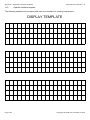
Operator interface template . . . .
14
INDEX . . . . . . . . . . . . . . . . . . . . . . . . . . . . . . . . . . . . . . . . . . . . . . . . . . . . . . . . . . . . . . . . . . . . Page 121
Copyright © 2006 Pan Controls Limited
...
...
..
...
...
...
.
.
.
.
.
.
.
.
.
.
.
.
.
.
.
.
.
.
.
.
.
.
.
.
.
.
.
.
.
.
.
.
.
.
.
.
.
.
.
.
.
.
.
.
.
.
.
.
.
.
.
.
.
.
.
.
.
.
.
.
.
.
.
.
.
.
.
.
.
.
.
.
.
.
.
.
.
.
.
.
.
.
.
.
.
.
.
.
.
.
.
.
.
.
.
.
.
.
.
.
.
.
.
.
.
.
.
.
.
.
.
.
.
.
.
.
.
.
.
.
.
.
.
.
.
.
.
.
.
.
.
.
.
.
.
.
.
.
.
.
.
.
.
.
.
.
.
.
.
.
.
.
.
.
.
.
.
.
.
.
.
.
.
.
.
.
.
.
.
.
.
.
.
.
.
.
.
.
.
.
.
.
.
.
.
.
.
.
.
.
.
.
Page
Page
Page
Page
Page
Page
101
101
115
116
118
120
Page iii
VC1 Controller User Manual
Page iv
Revision 1.9
Copyright © 2006 Pan Controls Limited
Revision 1.9
VC1 Controller User Manual
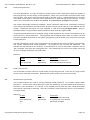
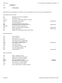
1
DOCUMENT MANAGEMENT
1.1
Release
Issue
1.1
1.2
1.3
1.4
1.5
1.6
1.7
1.8
1.9
1.2
Date
August, 1998
April, 1999
February, 2000
February, 2001
April, 2001
June, 2001
September, 2001
August, 2003
January, 2006
Comments
First release
Mk II keypad
Rev F control board
Mk III keypad
Updated diagrams
Option for new low end controller
Improved display commands
Corrected referencing commands
Software
V106.7
V107.3
V107.8
V109.0
V109.1
V109.1
V109.4
V109.7
V109.7
Critical changes to software
The purpose of this section is to highlight changes to software revisions, where there could be compatibility
problems with previous versions.
1.2.1
Version 107.6 (October 1999)
The SK command has had keys re-allocated to it. This means it is possible the a programme written for an
earlier version of software will need to be changed. For example SKK5 now enables sequence 5 to be executed
after pressing the right hand display key; previously it was after the escape key.
1.2.2
Version 107.8 (February 2000)
The RM (reference mode) command has been removed. The same functions are now carried out by the EI
(Enable input) and MI (Mask input) commands, when the inputs referred to have been defined for reference
activities.
1.2.3
Version 108.0 (March 2000)
The SU(Set Units) command has been removed. The variable system allows scaling to be performed more
flexibly.
1.2.4
Version 109.7 (August 2003)
The EP, LP, XP, and PV profile commands have been removed. This is to make room for other more useful
commands.
Copyright © 2006 Pan Controls Limited
Page 1
VC1 Controller User Manual
1.3
Revision 1.9
Key additions to software
The purpose of this section is to highlight additions to the language in software revisions.
1.3.1
Version 106.6
July 1998 - First variant of software with daughter board
1.3.2
Version 106.7
August 1998 - Added display/keypad features to controller
Added reset of parameters on fifth LED light after switch on
Allowed SP without interfering with DAC
1.3.3
Version 106.8
August 1998 - Added display pos snapshot and referencing
1.3.4
Version 106.9
October 1998 - Fixed bug with VT
Improved MD with no parameter
Allowed 256 numeric variables (%)
Added VO, UR, UM, UD, UO
1.3.5
Version 107.0
October 1998 - Added EE, HS. Fixed LL.
1.3.6
Version 107.1
October 1998 - Added selective SP(v).
1.3.7
Version 107.2
October 1998 - Fixed problem with numeric variables
1.3.8
Version 107.3
April 1999 - Fixed keypad scanning in rp loops
added reset and snapshots for b channel
1.3.9
Version 107.4
June 1999 - Set up for new keypad
1.3.10
Version 107.5
September 1999 - Corrected snapshot
1.3.11
Version 107.6
Added HR reset (watchdog)
- allowed all keys on Calman keypad
- enabled wired or mode for keypad outputs
1.3.12
Version 107.7
Jan 2000 - separated SPV ans SP functions
1.3.13
Version 107.8
Jan 2000 - added GL, EC, W X ,ZX & RX commands
1.3.14
Version 107.9
Feb 2000 - added NE & ZD commands
Page 2
Copyright © 2006 Pan Controls Limited
Revision 1.9
1.3.15
VC1 Controller User Manual
Version 108.0
Mar 2000 - Allowed rev f board with direct bus display
Fixed arrow key masking bug
1.3.16
Version 108.1
Apr 2000 - Allowed rev c daughter board
Allowed bounds counter for aux channel
Removed RM
n.b. Uses memory map which requires Config register to disable
EEPROM. Use DD command having entered priveleged mode using /*Pan*/
password. DP shows current state of CONFIG register ($0F factory setting - $0E after DD)
DC shows hex memory table, starting address from variable A
Allowed rev c daughter board
1.3.17
Version 109.0
Nov 2000 - Split with operator interface code
1.3.18
Version 109.1
Feb 2001 - Scan for Calman mk 2 keypad
1.3.19
Version 109.2
June 2001 - Fixed bug with OX command
1.3.20
Version 109.3
August 2001 - Allowed KPO... SAO... etc to variables
1.3.21
Version 109.4
V109.4 - September 2001 - Added VBC/S, IC, IS
modified to allow 14 inputs with Rev C daughter board
1.3.22
Version 109.5
March 2002 - Fixed bug relating to upper & lower limits
Fixed PO, and allowed use with variables
1.3.23
Version 109.6
October 2002 - Added CE and PL
Fixed bug with KS to allow KSn to reset within sequence
1.3.24
Version 109.7
August 2003 - Added FN, ME, MV, and cursor control CR
Removed EP, LP, XP, & PV profile commands
Copyright © 2006 Pan Controls Limited
Page 3
VC1 Controller User Manual
2
Revision 1.9
INTRODUCTION
This document describes the Pan Controls motion control system.
The system controls a servo motor with position feedback. It monitors a second position channel, and provides
a second auxiliary analogue output. The second position channel can be used as an input to the system. For
example, the servo channel can follow the position encoder. The system may be set up with a Personal
Computer, using software provided. Programmes can be developed on a personal computer, and downloaded
to the controller. These can then be stored on the controller.
Digital control systems are not simple, but can be very useful when applied correctly. It is important to understand
the basics of the operation of the system before it is installed on an expensive machine. The system is
completely programmable in all aspects of its operation, and it is recommended that users carry out training to
experiment to familiarise themselves with the facilities available. This is best done on an off-line test machine
which is not directly linked into a production unit.
Page 4
Copyright © 2006 Pan Controls Limited
Revision 1.9
3
VC1 Controller User Manual
SYSTEM OVERVIEW
The control systems are based on a microprocessor running on Eurocard sized circuit boards, using established
hardware and software technology. The system is designed to be able to provide an integrated solution to a wide
range of motion control situations. There is an option for an integrated keypad an display.
3.1
Circuit boards
There are several different circuit boards which have been developed together with their associated software.
These consist of:
3.1.1
Control board (PC3/120). This is a microprocessor driven circuit board, based on a Motorola
68HC11 microprocessor. It communicates with a personal computer by an asynchronous serial
port. Its functions include:
(i)Up to 2 channels D to A output (12 bits resolution). Bipolar -10/+10v output.
(ii)8 channels A to D input (8 bits resolution). These channels are not isolated, and must be in the
range 0-5v.
(iii)2 channels Quadrature & ref input. RS-422 inputs (differential signals).
(iv)4 channels of general purpose parallel inputs (2 of which may be used for reference inputs). 5v
un-isolated inputs.
(v)4 channels of general purpose parallel outputs. 5v un-isolated outputs.
(vi)2 asynchronous serial ports. One of these is also taken to an isolated RS-485/422 circuit for use
on a proprietary bus, or general purpose RS-422.
(vii)Hardware watchdog.
(viii)Scanning keypad interface (8×8).
(ix)LCD/VFD character display interface.
(x)EEPROM facility for parameter storage.
(xi)Site for daughter board.
3.1.2
Control daughter board (PC3/121). This is a daughter board, for use with the PC3/120 board.
It communicates with the host control board by an asynchronous serial port. Its functions include:
(i)Up to 8 channels isolated parallel outputs.
(ii)Up to 16 channels isolated parallel inputs.
(iii)Up to 4 channels stepper control.
(iv)Hardware watchdog.
(v)Scanning keypad interface (8×8).
Copyright © 2006 Pan Controls Limited
Page 5
VC1 Controller User Manual
4
Revision 1.9
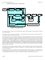
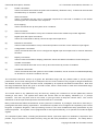
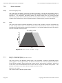
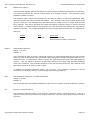
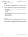
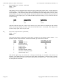
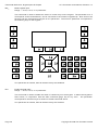
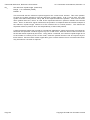
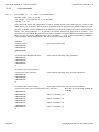
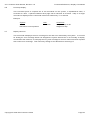
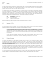
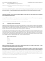
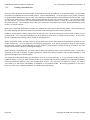
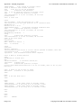
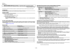
GENERAL DESCRIPTION - CONTROLLER
Target
Demand
Dem-Pos
)pos
)dem
Kp/Ki/Kd
Kf
DA
C
Kv
Counters
Drive
Motor
ISp
Tacho
Incremental encoder
Control board (PC3/120)
This section gives an overview of the operating principles and a brief description of the facilities of the digital
motor control system.
The hardware resides on Eurocard circuit boards. The host processor, and the motion control interface for two
axes are taken from an PC3/120 circuit board.
The control system works on the basis of continually sampling information and performing a control algorithm
at a defined timer interval (known as the sampling time). This sampling time is set to be 1÷256 th second. In other
words, the time interval between updating calculations is about 3.9ms. The control software uses two key pieces
of information to generate a positional error. These are the current demanded position, and the current
measured position. The demanded position is calculated by the controller on the basis of a target positional
move. For example, if the controller is asked to move a distance of 4000 encoder counts at a speed of 500
counts/sec and an acceleration of 2000 counts/sec², it can generate a velocity profile in terms of the desired
position at every 1÷256 th second. If the system is under control but not moving, there will still be a demand
position, but it will not change.
This positional error information is used as the basis for a PID (proportional, integral, and derivative) calculation,
whose output is fed to a Digital to Analogue Converter (DAC). The analogue voltage is sent to an analogue drive
as a velocity command.
Most high performance drive systems will have an analogue velocity control loop built in. This takes the form
of a Tacho-generator on the end of the motor shaft, which generates a voltage proportional to its velocity, and
an associated gain potentiometer on the drive. This allows a stable, high gain system to be set-up.
Page 6
Copyright © 2006 Pan Controls Limited
Revision 1.9
VC1 Controller User Manual
There are two additional control terms built in to the software, which can be useful under particular
circumstances. The first of these is a digital velocity feedback system. This is only really useful where no tacho
feedback is available, and is bound to be of a lower performance that an analogue system due to the limitations
of digital sampling. The second is called velocity feed-forward, and is proportional to the rate of change
(derivative) of the internally generated demand position signal. This feature is particularly useful for helping a
mechanical system to anticipate changes in velocity.
The system is intended for use with digital incremental position encoders which provide two signals in quadrature.
The encoder interface multiplies the resolution of the encoder by four, such that each complete cycle of the
encoder signals represents four counts.
The encoder signals are decoded and counted by hardware on the PC3/120 board. The software converts these
to numbers which represent the measured position. This signal is then used to compare with the demanded
position information, as described above.
The system is set up by high level commands from a serial link. Most commands are two letters, sometimes
followed by a numerical parameter. These commands can be built up into programmes which can then be
stored on non-volatile memory (EEPROM) on the system. The motors may be controlled using simple
proportional control, where the demand signal depends on only the position error. The proportional gain constant
is set by the user. It is also possible for the user to set gain constants for integral feedback, differential feedback,
velocity feedback, and velocity feed-forward terms, providing very flexible control over the system transfer
function.
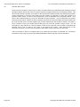
W hen a move command is entered, the system moves the motor according to a trapezoidal velocity profile
defined by the acceleration, velocity, and distance of the requested move. The system velocity and acceleration
may be set by the user. The motor speed increases at the set acceleration until it reaches the set velocity. It
continues at this velocity until it is near enough to the required position to begin decelerating. The system
calculates the point at which it should start decelerating, to minimise any overshoot. The rate of deceleration at
the end of the move is the same as the acceleration at the start. If the change in position is small, the motor may
not reach the set velocity, and will follow a triangular profile instead.
The motors may be controlled at a constant velocity instead of controlling the motor position. In velocity control
mode, the system accelerates the motor until it reaches the specified system velocity, and then maintains that
velocity. The motor may be stopped with the normal deceleration, or may be stopped abruptly in an emergency.
The system has up to 16 digital input and 8 output lines, which may be used in various ways. Inputs may be
programmed to start either single commands such as a move or stop command, or to execute a string of
commands or a stored sequence. Outputs may be set and cleared, and can be used to control external relays
or valves, or just be used for status indication. They may also be used to allow the system to be controlled from
an industrial programmable logic controller (PLC).
The facilities allow the user to define move profiles other than a trapezoidal or triangular profile, in order to follow
a specific motion, or to mimic some mechanical system. Sequences of commands may also be defined by the
user.
The use of variables allows a fixed programme to operate in a flexible manner.
Copyright © 2006 Pan Controls Limited
Page 7
VC1 Controller User Manual
5
Revision 1.9
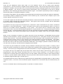
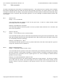
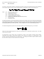
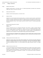
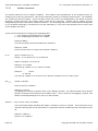
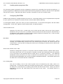
GENERAL DESCRIPTION - SOFTWARE FUNCTIONALITY
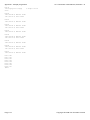
Data flow diagram
The control software is highly deterministic, being interrupt driven by a hardware timer. The control algorithm
is implemented every time this hardware timer generates an interrupt (every 1÷256 second). In addition, polling
of the external inputs is carried out during the same servo loop closure process. Serial character receipt and
transmission is also handled by the interrupt mechanism, and a special high priority interrupt is used for reference
marker detection. This gives a response time of better than 15µs.
The command interpreter is executed in background mode, together with display routines.
The modular approach to the software means that system can be easily adapted to particular situations.
Page 8
Copyright © 2006 Pan Controls Limited
Revision 1.9
6
VC1 Controller User Manual
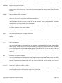
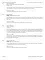
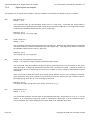
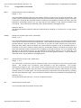
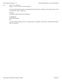
MODIFICATIONS TO THE USER PROGRAMME
The user programme consists of sequences of instructions which are stored in non-volatile memory on the Pan
controller.
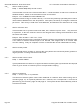
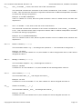
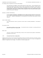
To make the management of the construction of the user programme simple, a system has been developed to
allow the user to develop and modify a master copy of the user programme on a personal computer.
The sequence of programme development can be summarised as follows:
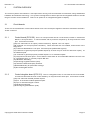
1 Develop programme on personal computer using any editor which will generate an ASCII file (i.e.
no embedded control codes).
2 Download programme from personal computer to Pan controller (to the controller's RAM - volatile
memory).
3 Save the programme from the controller's RAM to EEPROM (non-volatile memory).
This procedure means that a master copy of the programme is always maintained on a personal computer, and
can be copied and maintained for archiving purposes.
A utility programme (called "PANTERM") is supplied to run on an MS-DOS based personal computer. This
enables the personal computer to emulate a terminal, and to allow file transfer. The personal computer must
have a serial port ("COM1", "COM2", "COM3", or "COM4").
It is suggested that a batch file be set up to enable the user to enter the programme by entering a single name
(e.g. control). This will start the "PANTERM" programme, and prompt the user to press a key to start terminal
emulation.
If the Pan controller is connected to the personal computer and switched on, then any keys which are pressed
on the personal computer will be echoed back to the screen. If characters are not echoed, then there is
something wrong with communications. The leads should be checked. Also, the "PANTERM" configuration can
be modified by pressing <ALT> C. A sample screen might appear as follows:
Configuration
Communications Port (1 - 4):
Baud Rate:
Serial mode; RS232, 422 or 485:
File loading delay (milliseconds):
File loading mode: Transparent or Check for acknowledge
Software or Hardware handshaking:
Colour or Mono display:
Parity: None or Even:
Editor name:
1
9600
232
0
C
S
C
E
ed
In order to modify a source programme, it is necessary to access the editor by pressing <ALT> E. The user is
then prompted to enter a file name (e.g. "ICI6.1"). The editor then enables the user to move around the
programme, using the cursor keys and the <Page Down> & <Page Up> keys.
Modifications can be made until the user is satisfied. The user can then leave the editor by pressing <esc>
followed by E (to Exit and save), followed again by <esc>.
In order to download a source programme from the personal computer to the Pan controller, it is first necessary
to ensure that the controller is in the "privileged mode" (see command "PM"). It is suggested that the user resets
Copyright © 2006 Pan Controls Limited
Page 9
VC1 Controller User Manual
Revision 1.9
the controller to its default state by using the "RS" command, particularly when doing a final installation. This will
enable a definite checksum to be established on a particular machine. This means that any subsequent changes
(accidental or intentional) can be identified. If the file loading mode is set to C (checksum), The programme is
downloaded by pressing <ALT> U. The user is then prompted to enter a file name (e.g. "ICI6.1"), and the
programme will then be transferred. If the programme uses stored profiles, these will need to be downloaded
in the same way (e.g. ICI6.PRF).
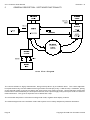
ASCII
programme
Volatile memory (RAM)
User's editor
Non-volatile memory (Flash)
Personal Computer
(Diagnostic terminal)
PAN controller
PANTERM programme maintenance environment
Page 10
Copyright © 2006 Pan Controls Limited
VC1 Controller User Manual, Revision 1.9
7
COMMAND DESCRIPTION
7.1
General
Command Description, General
This section gives full details of all the system commands and syntax. Numeric parameters are denoted by "nn".
Parameters entered as a binary string ("0"s and "1"s) are denoted by "bb". All commands are terminated by a
carriage return (CR) or by a carriage return and line feed (LF). The system responses are all followed by
(CR)(LF).
Numeric parameters are input and output in either decimal or hexadecimal. Commands are available to set the
system to use one or the other. Decimal numbers are output by the system as signed seven digit numbers.
Hexadecimal numbers are output in 24 bit two's complement format as six hex digits with no sign. Leading zeros
are not suppressed in numeric outputs. Decimal numbers are entered as signed or unsigned (assumed positive)
numbers. Hex numbers are entered as signed 23 bit or unsigned 24 bit two's complement numbers. Leading
zeros may be omitted. Any number may be entered as a variable (a to z) by suffixing the command with a "V"
followed by the variable. In addition, commands which output numeric data may be re-directed to a variable by
suffixing the command with an "O" followed by the variable.
The normal character set consists of the letters A-Z and a-z, the numbers 0-9, "+", "-", and space. Multiple
command sequences may be entered as one command line, with the individual commands separated by a
delimiter character. Any "/" character may be used as a delimiter between commands. The maximum input line
length is 255 characters. Backspace or delete may be used to remove characters from the current input line.
Command extensions usually use a ":" character to separate parameters. Other non-printing characters are
simply echoed, and have no effect.
The escape character (Hex 1B) will exit from any command which is producing a long list of many pages. The
tilde (~) character (Hex 7E) will cause the system to halt any current activity and perform a soft reset.
For systems without a keypad and display, the commands which relate to this hardware will obviously not
function.
The commands allow very flexible control of the system. They fall broadly into the following categories.
(a)
Miscellaneous.
Commands to change between channels, and to handle the stored setup data.
(b)
Mode commands.
These include commands to change between motor off and position control modes, and between
privileged and normal modes.
(c)
Move commands.
These include commands to move to absolute and relative positions, to find the zero reference
position, to move at a constant velocity, and to stop the move either normally or abruptly.
(d)
Set parameter commands.
These commands set up a wide range of system parameters, including the velocity and acceleration
of the normal moves, and setting up the creep and deadband facilities.
(e)
Sequence commands.
These include commands to enter, list, and execute complex command sequences.
Copyright © 2006 Pan Controls Limited
Page 11
Command Description, General
VC1 Controller User Manual, Revision 1.9
(f)
Profile commands.
These commands are used for the profile move facilities ("Software Cam"). Profiles can be executed
simultaneously on channels 1 and 2.
(g)
W ait commands.
These commands may be used in command sequences to wait until a condition is true before
executing the next command in the sequence.
(h)
Error trapping.
These commands set up the system error conditions.
(i)
Gain commands.
These include commands to set up the constants used in the closed-loop control algorithm.
(j)
Digital input and output commands.
These are commands to directly control the input and output lines.
(k)
Reference commands.
These include commands to set up continuous position correction on the reference input signal.
(l)
Configuration commands.
These commands allow the user to configure the digital input and output lines for various automatic
functions.
(m)
Display commands.
These include commands to display parameter values and status information via the serial port.
(n)
Variable commands.
These commands allow the user to set up and read values by means of variables.
(o)
Conditional commands.
These commands allow the system to test certain conditions, and to execute commands depending
on whether or not those conditions are met.
The command reference section (7.2) gives the allowable range and any default value of all the system
parameters, and in most cases gives an example of the use of the command. Any lengths or length related units
are defined in terms of position encoder counts, multiplied by an optional user-defined scale factor. Note that
the range and default values are given in encoder counts, and if a scale factor is used then the allowed range
and default values change accordingly.
The current value of any parameter may be found by entering the command to set the parameter, without
entering a new value. The system then shows the current value on the display, followed by a "?" prompt
character. The user may then enter a new value, or just type return to keep the current value. The current
definitions of all the input and output lines are listed with the LI command.
Many commands that affect the behaviour of the system are restricted, or privileged, and can be used only in
privileged mode after entering a password. This allows the system to be configured as required by the Control
Engineer or Systems Engineer, while preventing access to the more fundamental setup parameters by the
machine operator. The system can be programmed to start up automatically, or to operate from external digital
signals.
The complete system setup, including all parameter values, input and output line definitions, sequences and
profiles, may be stored in non-volatile memory using the SP save parameters command. The setup data is
Page 12
Copyright © 2006 Pan Controls Limited
VC1 Controller User Manual, Revision 1.9
Command Description, General
saved together with a checksum value. This is used when the system is initially powered up, to check the
integrity of the stored data. If the data has changed at all, the checksum test fails, and the system gives an error
message and resets the system to the manufactured default configuration.
Copyright © 2006 Pan Controls Limited
Page 13
Command Reference, Boot Programme
7.2
7.2.1
VN(D)
VC1 Controller User Manual, Revision 1.9
Command Reference
Miscellaneous commands
Display version number.
This command prints information about the version of software fitted to the system. It gives the
version number of the firmware, its revision date, and some configuration information. If there is user
programme information (entered using the EV command, page 15), it will also be displayed. The
optional D parameter re-directs the version information to the display unit.
SP(V)
Save parameters. (restricted)
This command saves all the programmable parameters in non-volatile memory. There may be a
short delay while the save operation takes place. The saved parameters become the new defaults,
used by the system on power-up. The SP command also saves any profiles sequences, and
variables A-Z together with numeric non-volatile variables. At the end of the save operation, the
system calculates a cyclic redundancy check byte (CRC) on the saved data, which is then saved
in non-volatile memory as well. This allows the saved data to be verified at any time by comparing
the stored CRC byte with a calculated one. If the saved data has changed at all, the stored CRC will
not be the same as the calculated CRC. The optional V parameter allows only the numeric nonvolatile memory to be saved. This can be useful when these variables are being used to save
operator programmes, and need to be saved regularly. Since none of the other system parameters
are being saved, this operation can be considerably faster than SP with no parameter. If the save
operation fails for any reason, then an "F" error message is returned. In this case, please contact
your sales office. This command is restricted, and is only available in privileged mode.
CS
Checksum test.
This command is used to verify the data stored in the non-volatile memory. The system calculates
a new CRC value for the stored data, and displays it. It then compares the new value with the CRC
value that was stored with the data when it was saved. If the values are different, an "F" fail error
message is displayed. If the CRC test fails, it indicates that the stored data has changed since it was
saved. If this occurs, please contact your supplier.
RD
Reload stored data. (restricted)
This command reloads all the parameters, input and output line definitions, sequences and profiles
from the stored setup in the non-volatile memory. If the stored data checksum is not correct, then
this command returns the 'F' failed error message, and the stored data values are not loaded.
RA
Reverse analogue output sense
This command reverses the output sense of the main control DAC. The command actually toggles
the sense of bit 4 of the control word.
Page 14
Copyright © 2006 Pan Controls Limited
VC1 Controller User Manual, Revision 1.9
RE(2/B)
Command Reference, Miscellaneous Commands
Reverse encoder input sense
This command reverses the input sense of either encoder. The command actually toggles the
sense of bit 4 of the control word. The suffix 2 or B reverses the input sense of the auxiliary channel
encoder.
RS(D)
Reset to default setup. (restricted)
This command resets all the parameters, variables except numeric type, input and output line
definitions, sequences and profiles to their default settings.
On power-up, the system recalculates the checksum on the saved data in the non-volatile memory.
If the calculated checksum does not match the stored checksum, then the RS function is executed
automatically to reset the system to its default state.
If the reset button is pressed during the fifth ON period of the flashing L.E.D. after power up, then
the system will reset to its default values.
If the optional "D" parameter is used, the display unit is re-written.
HR nn
Set Hard Reset sequence or initiate Hard Reset.
Range : 0 to 255
Default : 0
This command locks the software watchdog in order to force a system reset (after about 2 seconds).
LA
List all parameters.
This command lists all the parameters(with the exception of the HW hardware setup word and DW
display word), input and output line definitions, sequences and profiles to the serial port in a suitable
format for entering parameters etc. at a later date. If the system is connected to an MS-DOS based
personal computer running the PANTERM programme, the parameters can be recorded on disk for
backup purposes and loaded into another control system to duplicate parameter setting from one
machine.
BH
Breakdown of current Hardware.
This command displays the hardware which the software has recognised when the system has been
switched on. This information is saved, together with the stored parameters. If the hardware found
does not match the stored parameters, then the system will be reset, and a warning will be sent to
the screen.
EV"ccc"
Enter a user software revision no string.
This stores a character string (enclosed by double quotes, maximum 16 characters). This can be
useful for identifying the current setup, using the VN command.
Copyright © 2006 Pan Controls Limited
Page 15
Command Reference, Miscellaneous Commands
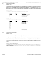
GW bbbb
User Manual, Revision 1.9
Set global control word. (restricted)
Range : 0000 0000 to 1111 1111 (binary).
Default : 0000 0000
This command allows the user to write a value into the global system control word. Note that the
leading zeros may be omitted. The global control word allows various components of the system
to be enabled and disabled, as required. The global control word bit functions are described below.
bit
Page 16
Bit set
Bit cleared
Vacuum Fluorescent display brightness BR0 (see table below)
Vacuum Fluorescent display brightness BR1 (see table below)
Reserved for future expansion.
Reserved for future expansion.
Reserved for future expansion.
Unipolar velocity signal output (0-10v)
Bipolar velocity signal output (0-±10v)
Reserved for future expansion.
Reserved for future expansion.
0
1
2
3
4
5
6
7
Bit 1 (BR1)
Bit 0 (BR0)
Brightness
0
0
1
1
0
1
0
1
100%
75%
50%
25%
Copyright © 2006 Pan Controls Limited
VC1 Controller User Manual, Revision 1.9
7.2.2
LM
Command Reference, Mode Commands
Mode commands
Link axis to second encoder
Links the motion of the controlled axis to the second encoder. The second encoder and the
controlled axis will be linked by a ratio defined by the FD and FM parameters. If a velocity link is
defined (using the LW parameter), the current axis will increase in velocity by the defined
acceleration rate until it reaches the desired velocity (i.e. the velocity of the channel being followed,
multiplied & divided by its FD and FM parameters). The derived velocity (which can be averaged
using the VT parameter) from the channel which is being followed (the second encoder) will be used.
The ST command will cause the motor to decelerate from its current velocity to a standstill, using a
deceleration rate defined by the SA parameter.
FD n
Set link factor for division.
Range : 0 to 16
Default : 0
This command sets the division factor for linking one axis to another. The actual position data is
divided by 2 n in conjunction with being multiplied by the FM parameter. The largest division factor
is 256.
Example : FD 4
This sets the link division factor to 2 4 = 16.
FM n
Set link factor for multiplication.
Range : 1 to 65535 or -32767 to 32767
Default : 256
This command sets the multiplication factor for linking one axis to another. The actual position data
is multiplied by n÷256 in conjunction with being divided by two to the power of the FD parameter.
The largest multiplication factor is 65535 (÷256). If bit 7 of LW is set, then negative multipliers are
allowed.
Example : FM 9
This sets the link multiplication factor to 9.
Example : FM 5888/FD5
This sets the link multiplication factor to 5888, and the division factor to 2 5 = 32. The resultant factor
is therefore 5888÷256÷32 = 0 @71875.
Copyright © 2006 Pan Controls Limited
Page 17
Command Reference, Mode Commands
LW bbbb
VC1 Controller User Manual, Revision 1.9
Link motions control word. (restricted)
Range : 0000 0000 to 1111 1111 (binary).
Default : 0
This command allows the user to set various motion linking control options. Note that the leading
zeros may be omitted. The link motions control word bit functions are described below.
bit
PC
0
1
2
3
4
5
6
7
8
Bit set
Position link
Reserved for future expansion.
Reserved for future expansion.
Reserved for future expansion.
Reserved for future expansion.
Reserved for future expansion.
Reserved for future expansion.
Reserved for future expansion.
Allow negative multiplier for FM
Bit cleared
Velocity link
Positive multiplier only for FM
Enter position control mode.
This command puts the system back into the normal state with the motor position continuously
controlled, after an MO command has been executed, or a position error abort has occurred. The
prompt character ">" is returned in position control mode.
In position control mode, an onboard relay on the hardware is energised such that the motor
command signal is available from the command signal output. The spare contacts of the relay are
also switched over, for use as a drive enable signal if required.
MO
Motor off.
Turns off the position control servo loop action. All other facilities still operate normally, including the
input and output lines, and the encoder position is continuously monitored. W hen the system is
returned to position control mode, the motor does not jump back to its last controlled position, but
remains at its new position. The system returns a ":" character as a prompt when in the motor off
state.
In the motor off state, the motor command signal output is switched directly to 0v by the onboard
relay. The spare relay contacts are also switched to their normal unenergised state. It is
recommended that this relay is used to disable the drive completely. If the drive is not disabled in
the motor off state, then it is likely that the motor position will drift, due to some offset in the drive
circuits, since the motor position is not controlled in this state.
The MO command may also be used as a third stop command, to put the motor directly to the motor
off state from any other state, instead of using the ST stop or AB abort commands.
Page 18
Copyright © 2006 Pan Controls Limited
VC1 Controller User Manual, Revision 1.9
PM
Command Reference, Mode Commands
Enter privileged mode.
For most applications, it is only necessary to make full use of the command set when the system is
first programmed, and not during normal operation. Many of the commands control the basic setup
of the system, such as the gain commands used to tune the system. Unauthorised access to these
commands could result in a severe loss of performance or even damage to the machine. For this
reason, the command set is divided into normal, and restricted or privileged commands.
The normal commands are always available. These include the basic move commands, and many
of the simple set parameter commands such as those used to set the velocity or acceleration for the
system. Restricted commands are only available in what is termed privileged mode. Entry to
privileged mode is only permitted with a password, which itself is programmable.
If restricted parameters must be changed during normal operation, the relevant commands may be
executed from a stored sequence. This bypasses the privileged mode check at runtime, but still
prevents unauthorised access to the system programming since the ES enter sequence command
is also restricted.
The PM command is used to enter privileged mode and gain access to the complete command set.
The system responds with "Enter password: " to prompt the user to enter the password. The
password is not echoed as it is entered. If the password is correct, the system responds with an
"OK" message, and goes into privileged mode. If the password is incorrect, the system sends an
"E" error message and stays in normal mode.
Example :
System
>
Enter password:
>
NM
User
PW <CR>
(password)
Comments
Set password command
The new password is echoed
Enter normal mode.
This command is used to return to normal mode from privileged mode, if the user no longer needs
access to the restricted commands. Note that the system powers up into normal mode.
PW
Set password. (restricted)
This command allows the user to set the privileged mode password. The system replies "Enter
password: ", and the user should then type in the new password. The new password is limited to a
maximum of ten characters. It is saved in non-volatile memory with the other setup parameters
when the SP command is executed. The PW command is itself restricted, and is only available in
privileged mode.
Example :
System
>
Enter password:
O.K.
>
Copyright © 2006 Pan Controls Limited
User
PW <CR>
(password)
Comments
Privileged mode command
The password is not echoed
Password accepted
Page 19
Command Reference, Move Commands
7.2.3
AB(K)
VC1 Controller User Manual, Revision 1.9
Move commands
Abort, emergency stop.
The motor stops immediately, ignoring the system acceleration. This may be used instead of the ST
command, where an abrupt stop is required. The AB command may also be used to break out of
sequences. The optional K parameter enables a selective abort from any pending keypad
operations (e.g. VK), whilst maintaining all other current system operations. Likewise AB without the
K parameters maintains any current keypad operations, whilst stopping all motion operations.
ST nn
Stop.
The motor stops under controlled deceleration, set by the SZ command. The stop command may
be used during a normal move or constant velocity move to decelerate the motor to a stop. The ST
command may also be used to break out of sequences. The optional parameter allows the stop to
finish at a defined absolute position.
Figure 2 Move with normal stop
MA± nn
Move to absolute position ± nn.
Range : ± 4 000 000 (4.0E6) encoder counts.
The motor moves to the absolute position given in the command. It follows a trapezoidal velocity
profile (graph of velocity against time). The motor accelerates from rest at the system acceleration,
set by the SA command, until it reaches the system velocity, set by the SV command. At the end
of the move, the motor decelerates at the same rate to stop at the desired final position. The
position is entered in user units, which are equal to encoder counts.
Example : MA +2000
The motor moves to absolute position 2000.
Page 20
Copyright © 2006 Pan Controls Limited
VC1 Controller User Manual, Revision 1.9
MR± nn
Command Reference, Move Commands
Move ± nn units relative to current position.
Range : ± 8 000 000 (8.0E6) encoder counts.
The system performs a move similar to the absolute move above, but the move distance is defined
relative to the current position. The move distance is entered in user units.
Example : MR -3000
The motor moves 3000 units from its current position in the negative direction.
VC±
Move at constant velocity.
The system accelerates the motor at the system acceleration until it reaches the system velocity,
in the specified direction. It then controls the motor at constant velocity, until asked to stop by the ST
command. Velocity control mode can only be entered from position control mode, and not directly
from the motor off state.
Example : SA 1000/ SV 2000/ VC+
This command sequence sets the acceleration to 1000 units per second squared, the velocity to
2000 units per second, and then accelerates to the set velocity in the positive direction.
IN±
Initialise position.
The system performs the initialisation sequence to find a zero position reference signal. The system
gives the "I" initialise prompt character while executing the initialisation sequence. The motor
accelerates to the system velocity in the specified direction. W hen the system detects a reference
input signal, it resets the position counters to zero immediately. The motor then decelerates to a stop
and moves back to the new zero position.
NOTE: The IN command works independently of the settings of all the other reference commands.
This is so that whatever the reference setup for normal running, the IN command always works
normally. The exceptions to this are bit 3 of the RW reference options word, which disables the
move back to the new zero point, and bit 4 of RW which defines whether any reference input is valid,
or only a combination of them. The reference offset value is also effective during the initialisation
sequence, such that the position at which the reference signal is detected is defined as the absolute
position given by the value of RF, not necessarily zero. For more details read the reference
command section (section 7.2.10, page 50) later in this manual.
If no reference input or marker input is defined, then the IN commands returns the E error message,
and the initialisation sequence is not executed.
Example : RW 0 / IN +
The motor moves in the positive direction until the reference input is seen. It then stops, and in this
example it moves back in the negative direction to the reference position.
Copyright © 2006 Pan Controls Limited
Page 21
Command Reference, Move Commands
ID
VC1 Controller User Manual, Revision 1.9
Initialise DAC offset.
Under normal conditions, there may be some constant offset in the demand signal analogue output
amplifiers which causes the motor to settle at a position slightly different to the required position. The
ID command sets the system up to allow for this (assumed constant) offset in all subsequent position
control operations. It must be used every time the system is powered on, when the system is in
position control mode, to set the actual position as close as possible to the required position. This
can be done automatically by using the autostart sequence facility. This is particularly necessary
when the final position window as set by the SW command is small, otherwise the output offset may
be such that the motor normally settles at a position outside the final position window, and after a
move remains in the move state without returning to the normal position control mode. The ID
command is only effective in normal position control mode, with the motor actually controlling the
position, and it has no effect if the motor is not driving the system. Note that friction in the
mechanical system can also cause a position offset after a move command is executed.
If this command is used on a regular basis (e.g. whenever the system is switched on), it will have
the effect of removing any drift in the analogue amplifier which may have arisen with time.
Page 22
Copyright © 2006 Pan Controls Limited
VC1 Controller User Manual, Revision 1.9
7.2.4
SW nn
Command Reference, Set Parameters
Set parameter commands
Set W indow. (restricted)
Range : 0 to 65535
Default : 10
This command sets a window around the required final position of a move. Its operation is such that
the system finishes a move and returns the prompt character to the user only when the motor is
within this window. Note that when using a narrow window, it is important that the DAC offset on the
current channel has been initialised with the ID command. If not, the offset may be large enough to
put the motor outside the window when it is stopped, and the system will stay in the move state
without returning the normal prompt. If this occurs, the ST or AB commands may be used to get
back to the normal state. Note that the window is specified in encoder counts. This command is
restricted, and may only be used in privileged mode.
Example : SW 25
This command sets the window to 25 counts. Thus the system returns the normal prompt at the end
of a move only when the motor is within 25 counts of the required position.
SB(B) nn
Set position overflow bound. (restricted)
Range : 1 to 4 000 000 (4.0E6)
Default : 4 000 000
This command sets upper and lower bounds on the absolute position of the system. If the position
of the motor exceeds the upper bound then the position bound value is subtracted from the current
position. If the position goes below the lower bound, the bound value is added to the current position
to keep the position within bounds. The suffix B sets the bounds for the auxiliary channel. Note that
this does NOT limit the range of any move commands, but only changes the value of the final
position for moves outside the position bounds. This is illustrated by the example below. There is
also a 32-bit position overflow counter which is incremented when the position passes the upper
bound, and is decremented when the position passes the lower bound. This effectively provides a
32-bit high order extension to the absolute position. The overflow count may be displayed by using
the DC command, and may be reset to zero by the RC command.
The bound position defined by the SB command is also used as the expected reference position
when the system is set up to continuously monitor the reference input. Refer to section 7.2.10 (page
50)for more details about the reference commands.
Example : SB1000
This sets the position bounds to ±1000 counts. An application of this is where it is required to know
the motor position to within one revolution of the motor only, but it is not necessary to distinguish
between complete revolutions of the motor. If a move from zero to position 1200 is executed, the
final position is 200. The motor has moved a total distance of 1200 counts as required, but the final
position is the remainder when divided by the bound value. If a move from zero to -1200 is
executed, the final position is -200. In this application, the position overflow counter represents the
number of complete revolutions of the motor from the zero position to the current position, and the
normal position value defines the position within one revolution.
Copyright © 2006 Pan Controls Limited
Page 23
Command Reference, Set Parameters
SV nn
VC1 Controller User Manual, Revision 1.9
Set velocity (speed).
Range : Creep velocity (SS) to 800 000 (8.0E5)
Default : 1024
This command is used to set the system velocity, in user units per second. It may be used when the
motor is stationary, or when moving at constant velocity after a VC command.
Example : SV 5000
This sets the system velocity to 5000 units per second.
SA nn
Set acceleration.
Range : 1 to 2 000 000 000 (2.0E9)
Default : 1024
This command sets the normal system acceleration to the specified value, in user units per second
squared. Note that the acceleration is rounded to the nearest multiple of 256, giving a resolution of
256 counts.
Example : SA 10000
This sets the system acceleration to 10000 units per second squared.
SC nn
Set creep distance.
Range : 0 to 65535
Default : 0
The normal trapezoidal velocity profile for a position move can be modified to include a slow speed
creep to the final required position. The creep distance is the distance from the final position over
which the system moves at the slow creep speed, set by the SS command. This may be used to
minimise overshoot at high speeds and accelerations.
Example : SC 200
This command sets the creep distance to 200 units. A position move command will now start to
decelerate earlier than normal, such that the system reaches the slow creep speed at least 200 units
before the final required position.
SS nn
Set slow creep speed.
Range : 1 to system velocity (SV)
Default : 32
This command allows the user to set the speed of the slow creep to the final position, if required. It
is specified in the same units as the system velocity.
Example : SS 100
This sets the slow creep speed to 100 units per second.
Page 24
Copyright © 2006 Pan Controls Limited
VC1 Controller User Manual, Revision 1.9
SD nn
Command Reference, Set Parameters
Set deadband.
Range : 0 to 65535
Default : 0
The system normally controls the position of the motor continuously, whether moving or stopped.
This command allows the user to set up a deadband about the nominal position, within which the
system will not control the position of the motor. This may be used, for example, to prevent hunting
in systems with mechanical backlash. The deadband only becomes active after the system has
reached the required position and the settling time, set by the SL command, has expired.
Example : SD 100
This sets the deadband to 100 units. The system will now only control the position of the motor if it
moves more than 100 units away from the required position.
SL nn
Set settling time.
Range : 0 to 65535
Default : 256
This command sets the time that the system waits, after reaching its required position, before the
deadband becomes active. It is specified in units of 1/256 seconds.
Example : SL 128
This sets the settling time to 128x1/256 = 0.5 seconds.
ZC[nn]
Zero position counters or set position.
If a position value is given, the system sets the current demand position to the given (absolute)
value. If no value is given, it sets the current demand position to be zero absolute position. The ZC
command may be used at any time.
Example : MA-5000/ ZC
This moves the motor to position -5000, and sets the position counters to zero at that position.
Example : ZC8000
This defines the current demand position as position 1000
RC(2/B)
Reset position overflow counter.
This command resets the position overflow counter to zero. The overflow is incremented when the
position exceeds the upper bound, and is decremented when the position passes the lower bound.
The suffix 2 or B resets the overflow counter for the auxiliary channel.
TS hh:mm:ss
Time set.
This command allows the user to set the system time. It expects the time to be in the format
Copyright © 2006 Pan Controls Limited
yy:hh:mm:ss
.
Page 25
Command Reference, Set Parameters
DB(K) nn
VC1 Controller User Manual, Revision 1.9
Set input debounce time. (restricted)
Range : 0 to 255
Default : 5
This command sets up a debounce time for all the digital inputs. It is specified in 1÷256 second
(about 4ms) ticks. Before an input signal is recognised as valid, it must be stable for the number of
samples given by the DB command. This facility may be used to reduce the effect of noise in a
system by reducing the number of false triggers due to noise. The suffix K allows the keypad
debounce time to be adjusted.
NOTE: The debounce value does not apply to reference inputs. These inputs are programmed so
as to be detected immediately on a change of state, to get the most accurate position information
possible.
Example : DB 2
This sets the debounce time to about 8 ms (2 samples).
Page 26
Copyright © 2006 Pan Controls Limited
VC1 Controller User Manual, Revision 1.9
7.2.5
Command Reference, Sequences
Sequence commands
This section describes the sequence facilities. They provide comprehensive facilities for defining, reviewing and
executing complex command sequences. Sequence definitions may be entered up to the memory capacity of
the system. If the system runs out of memory, it returns an "N" no room error message.
ES nn
Enter sequence.
Range : 1 to 255
This command is used to enter sequences into the system. The system responds with a "S nn:"
prompt for the sequence entries. Each entry in the sequence is any valid command line. Command
sequences on one command line are accepted as one sequence entry. Sequence entries may also
include commands to execute other sequences and profiles. To end the sequence, make a blank
entry by just entering a (CR), and the system then returns to normal operation. The sequence is
accessed by means of the sequence number assigned by the user when it is entered.
Example :
System
>
S1:
S1:
S1:
S1:
>
LS nn
User
ES 1 (CR)
ID/ IN - (CR)
MA100/ W T256/ MA0/ W T256/ RP3 (CR)
MA 2000 (CR)
(CR)
Comments
Enter sequence 1
Initialise position
Do this 3 times
A single move
End sequence
Normal prompt
List sequence.
Range : 1 to 255
This command allows the user to examine a sequence that has previously been entered into the
system. The sequence is listed on the display or terminal, one command entry per line. The
sequence may be listed continuously, or the system can print one line at a time and wait for the user
to press the (CR) key before printing the next line. This is useful when using the system with a
membrane keyboard or a hand-held terminal which only has a small number of display lines. This
list pause facility is controlled by one of the flag bits in the DW command.
Example : LS 1
This will list sequence 1 on the display or terminal. The output for the sequence given above would
look like this.
>LS 1 (CR)
S1: ID/INS1: MA100/W T256/MA0/W T256/RP3
S1: MA2000
>
Copyright © 2006 Pan Controls Limited
User input to list sequence.
Page 27
Command Reference, Sequences
XS nn
VC1 Controller User Manual, Revision 1.9
Execute sequence.
Range : 1 to 255
This command tells the system to execute sequence number nn. The normal status messages for
each part of the sequence are printed on the display as they are executed. The sequence will abort
automatically if any error condition occurs. A sequence may be aborted by using the AB command.
The ST stop command may also be used to stop the currently executing move command.
Example : XS 3
The system executes stored sequence no. 3.
RP nn
Repeat.
Range : 1 to 255, or no value
This command tells the system to repeat the sequence of commands on the current command line,
up to the RP command, nn times. If no repeat count is given, the system will repeat indefinitely.
Example : MA 2000, MA 0, RP5
This moves the motor to position 2000 and then back to position 0, repeated 5 times.
ER(F)
End repeat.
This command allows the user to exit from a repeat loop cleanly, at the end of the current loop. This
is in contrast to the stop and abort commands, which stop the system immediately, in the middle of
whatever action is taking place. It may be used in repeat loops with a repeat count, or in endless
repeat loops In either case, the loop terminates normally at the end of the command line.
W hen the ER command is executed, any commands following the original RP command are not
executed. Commands following the ER command are executed when the repeat loop terminates.
This allows a command line beginning with the ER command to override the current operation, and
neatly replace it with a new operation at the end of the repeat loop.
The optional F parameter allows the termination of a for-next loop next time the loop is completed
(See page 62).
HS nn
Display history of sequences executed.
Range : 1 to 255, or no value
Displays a list of the numbers of the most recent nn sequences executed in inverse chronological
order. If no parameter is given, all of the last 256 most recently executed sequences are listed.
Page 28
Copyright © 2006 Pan Controls Limited
VC1 Controller User Manual, Revision 1.9
SK(A-M )nn
Command Reference, Sequences
Execute sequence on keypad entry event.
Range : 1 to 255, or no value
This command sets up the system to execute sequence number nn as soon as the enter key has
been pressed on the keypad (after a VK command, page 75). This allows for the system to operate
in an asynchronous manner. The optional prefix parameter (A-M) allows non-numeric keys to start
events at any time. These keys can be selectively masked using the EK and MK commands (page
48).
Example : SK 56
The system executes stored sequence no. 56 after a variable has been entered using the VK
command.
Parameter
A
B
C
D
E
F
G
H
I
J
K
L
M
N
O
P
Q
R
S
T
U
V
W
X
Y
Z
CE nn
Operator interface Mk2
Operator interface Mk1
F1
F1
F2
F2
F3
F3
F4
F4
F5
F5
F6
F7
F8
Left display
Centre display
Right display
ESC
ESC
Left arrow
Right arrow
Up arrow
Down arrow
Secret key
Dot key
F9
(top left)
F10
(second top left)
F11
(third top left)
F12
(fourth top left)
F13
(top right)
F14
(second top right)
F15
(third top right)
F16
(fourth top right)
16-key Keypad
A
B
C
D
E
F
Execute sequence continuously as timed event.
Range : 0 to 255
This command sets up the system to execute sequence number nn as soon as the time defined by
the PL parameter has passed. This sequence will be repeated indefinitely at the defined time
interval until CE0 or an AB command is entered. Note that the time interval relates to the start of the
sequence, even if the sequence takes a significant time to execute.
Example : PL512/CE 12
The system executes stored sequence no. 12 after continuously every 2 seconds.
Copyright © 2006 Pan Controls Limited
Page 29
Command Reference, Sequences
PL nn
VC1 Controller User Manual, Revision 1.9
Set parameter for looping continuous event
Range : 20 to 65535
Default : 256
This command sets the time parameter for the CE continuous sequence command. The units are
system ticks (1÷256 second).
Example : PL128
This sets the delay between continuous sequence events to ½second.
EE nn
Execute sequence on error condition.
Range : 1 to 255, or no value
This command sets up the system to execute sequence number nn as soon as a system error state
is encountered. This allows for system to interrogate the system error and display an appropriate
message.
Example : EE 123
The system executes stored sequence no. 123 after an error state has been reached.
NE nn
Execute sequence after snapshot event
Range : 0 to 255
This command sets up the system to execute sequence number nn as soon as a snapshot event has
taken place. This command needs to be reset after each operation.
Example : NE 55
The system executes stored sequence no. 55 after an a snapshot event has taken place.
Page 30
Copyright © 2006 Pan Controls Limited
VC1 Controller User Manual, Revision 1.9
MF
Command Reference, Sequences
Display free memory.
This command displays information about the memory space available for sequences and profiles.
This command returns the amount of free space as a number of bytes. The maximum space
available is about 12 kbytes.
It is possible under certain circumstances for the internal memory to become fragmented, when
maps and profiles are being entered and deleted. This could give rise to the system reporting an
"N" out of memory error message when the total amount of spare memory is larger than the data
being entered. This occurs because the system allocates a contiguous block of memory for each
map or profile. A simple solution to this problem is to save and restore the parameters using the SP
and RD commands. This compacts the data and forces all the spare memory into one single block.
Example :
System
>
6538
>
AS(R)nn
User
MF<CR>
Comments
Enter MF command
System returns number of bytes free
Set autostart sequence.
Range : 0 to 255
Default : 0
This command is used to set up a command sequence to execute automatically when the system
starts up, after all the saved setup parameters and configuration details are loaded from the nonvolatile memory. If no sequence number is given, the system prints the current autostart sequence
number. If the "R" option is entered, an auto-start sequence for startup after software watchdog
reset can be entered. This could be the same as the AS auto-start sequence, but could be some
alternative sequence to ensure a safe re-start.
To disable the autostart sequence facility, set it to zero. If the sequence specified in the AS
command is not defined, then the system simply does nothing at start-up.
HR nn
Set Hard Reset sequence or initiate Hard Reset.
Range : 0 to 255
Default : 0
This command locks the software watchdog in order to force a system reset (after about 2 seconds).
XT
Exit from current sequence.
This command tells the system to exit from the sequence which is currently running. If this is a
sequence which has been called from another sequence, then the calling sequence will continue
execution.
Copyright © 2006 Pan Controls Limited
Page 31
Command Reference, Sequences
GL n
VC1 Controller User Manual, Revision 1.9
Go to line in sequence
Range : 1 to no of lines in current sequence
This command allows looping to a specified line number within a sequence. Note that it can only be
executed from within a sequence.
Example:
A sequence might consist of the following:
CO3/MR5000
SO4/W T500/II5-/XT
GL1
This will continue looping to line 1 until input line 5 is negative, when the XT command will escape
from the sequence.
Page 32
Copyright © 2006 Pan Controls Limited
VC1 Controller User Manual, Revision 1.9
7.2.6
Command Reference, W ait Commands
Wait commands
The wait commands are most useful in command sequences. They allow the user to specify some condition
that must be satisfied before the system will execute the following commands. The system returns a "W " status
message to indicate that it is waiting. If the position specified in a wait for position command is outside the range
of the previous move command, then the system gives an "O" error message to indicate that the position was
out of range.
W T nn
W ait for time.
Range : 0 to 2,147,483,647
This command tells the system to wait for the given time, in units of 1÷256 seconds, before
proceeding to the next command.
Example : MA 2000/ W T 512/ MA 0
This command sequence tells the system to move to position 2000, wait there for 2 seconds, and
then move to position 0.
W Inn±
W ait for input line nn.
Range : 1 to 8×n (where n=No of control boards)
This command tells the system to wait until the specified input line goes to the specified state. Note
that if the specified input line has been defined as some other function input, the system returns the
"U" line already used error message.
Example : MA 5000/ W I 2 -/ MA 0
This sequence tells the system to move to position 5000 units, wait there until input line 2 goes to
a logic low, and then move to position 0.
W A± nn
W ait for absolute position.
Range : ± 4 000 000 (4.0E6) encoder counts.
This command tells the system to wait until it reaches the given absolute position before executing
the next command. If the position specified in a wait for position command is outside the range of
the previous move command, then the system gives an "O" error message to indicate that the
position was out of range.
Example : SV 200/ MA 2000/ W A 1500/ SV 100
This sequence performs a move with a change of speed at a certain position. The velocity is initially
set to 200 units per second. The motor begins a move to position 2000 at this velocity, and at
position 1500 the velocity is changed to 100 units per second. The move is completed at the new
velocity.
Copyright © 2006 Pan Controls Limited
Page 33
Command Reference, W ait Commands
W R± nn
VC1 Controller User Manual, Revision 1.9
W ait for relative position.
Range : ± 8 000 000 (8.0E6) encoder counts.
This command is similar to the W A command above. It tells the system to wait until it reaches the
specified position, relative to the last position used in a command.
Example : VC+ /W R5000 /SV1000 /W R2000 /ST
The system starts moving at constant velocity. It moves at the previously specified system velocity
until it reaches 5000 units from the start position. At this point, the velocity is changed to 1000 units
per second. This velocity is held for the next 2000 units, and then the motor decelerates to a stop.
WF
W ait for reference input.
This command sets the system into the wait state, until a reference input is seen. It may be useful
in sequences, to allow the reference action to be changed after detecting the first reference since
the system was started.
Example : RW 10100001 / W F / RW 1 / SO3
This command string sets up the initial RW such that the reference input behaves as a fast ZC input.
It then waits for the first reference input to be detected, and changes RW to the normal autocorrection setting. Finally an output line is set to indicate that the unit has initialised and is ready.
WB
W ait for bound position.
This command tells the system to wait until the motor passes the next bound position (positive or
negative) before continuing with the command string.
W C± nn
W ait for bound overflow count.
Range : ± 2 000 000 000.
This command tells the system to wait until it the bound overflow counter increments (or decrements)
by the specified count before continuing with the command string. It may be used, for example, to
wait for a given number of machine cycles to complete before stopping.
W K(nn)
W ait for keypad entry
Range : 1 to 64, A to Z, or no parameter
This command sets the system into the wait state, until an value has been entered using the VK
command (page 75). An optional parameter can be entered, which corresponds to a code for the
particular key (see appendix, page 115 and page 48). The system will then wait until the key referred
to has been pressed.
Page 34
Copyright © 2006 Pan Controls Limited
VC1 Controller User Manual, Revision 1.9
WE
Command Reference, W ait Commands
End wait state.
This command ends the current wait state as if it had completed normally. This allows the user to
escape from a wait state early but to continue with commands following the wait command.
Example :
System
1>
User
DI1-/W E
Comments
Escape from wait state on input
line 1 going negative.
1>
In this example, channel 1 moves to position 10000, waits 4 seconds and then moves back to zero.
However if input line 1 goes negative during the wait state, the motor moves back to zero
immediately.
Copyright © 2006 Pan Controls Limited
Page 35
Command Reference, Error Trapping
7.2.7
SE nn
VC1 Controller User Manual, Revision 1.9
Error trapping
Set maximum position error. (restricted)
Range : 0 to 65535
Default : 800
This command sets a maximum position error which is continuously monitored by the system. If the
position error at any time exceeds this value, the system gives a "G" error message, decelerates to
a stop and enters the motor off state. The system must be returned to the position control mode
before any further motion commands are accepted by the system. See section 7.2.2 (page 17) for
details of the MO motor off and PC position control commands. The value is defined in user units.
Example : SE 500
This sets the maximum position error to 500 units.
TO nn
Timeout. (restricted)
Range : 1 to 65535
Default : 32
This command sets a timeout value, in units of 1÷256 seconds. W hen a move command is
executed, if the motor does not move for a period that exceeds the timeout, then the system will print
a "T" error message and go to the motor off state. The system must be returned to position control
mode before any further move commands are accepted.
Example : TO 512
This sets the timeout to 2 seconds.
LH± nn
Set high position limit. (restricted)
Range : ± 4 000 000 (4.0E6)
Default : + 4 000 000
This command sets up a user-defined limit position. If at any time the absolute position of the motor
exceeds the high position limit, the system gives the "LH" error message and goes to the motor off
state. This is similar to the action taken on detecting a limit switch input. The value is defined in user
units.
Page 36
Copyright © 2006 Pan Controls Limited
VC1 Controller User Manual, Revision 1.9
LL± nn
Command Reference, Error Trapping
Set low position limit. (restricted)
Range : ± 4 000 000 (4.0E6)
Default : - 4 000 000
This command sets up a user-defined limit position. If at any time the absolute position of the motor
is less than the low position limit, the system gives the "LL" error message and goes to the motor
off state. This is similar to the action taken on detecting a limit switch input. The value is defined in
user units.
Example : LH 10000/ LL 0
This sets the high position limit to 10000 units, and the low position limit to zero. If the motor position
goes outside the range 0 to 10000 units, the system gives the appropriate error message and goes
to the motor off state.
RT nn
Set reference timeout. (restricted)
Range : 0 to 255
Default : 0
This command sets up a timeout on the reference input. It is used when the system is set up for
continuous monitoring of the reference input, to give a warning error message if the reference input
is not detected. A counter is incremented each time the system passes a bound position, and
cleared each time a valid reference input is detected. If the counter reaches the "RT" value, the
system gives the "RT" error message. The reference timeout function may be disabled by setting
it to zero if it is not required.
Copyright © 2006 Pan Controls Limited
Page 37
Command Reference, Error Trapping
EW bb
VC1 Controller User Manual, Revision 1.9
Set local error options word. (restricted)
Range : 0000 0000 to 1111 1111 (binary)
Default : 0
This command allows the user to write a value into the error options word. Note that the leading
zeros may be omitted. The error word allows various user and motor error options to be turned on
or off. The error word bit functions are described below.
bit
LE
0 W hen set to 1, the reference timeout error is treated as a motor error, and the system goes to the
motor off state when a reference timeout occurs.
W hen set to 0, the reference timeout error is treated as a user error, and the system simply prints
an error message.
1 W hen set to 1, the reference limit error is treated as a motor error, and the system goes to the
motor off state when it occurs.
W hen set to 0, the reference limit error is treated as a user error, and the system simply prints an
error message.
2 W hen set to 1, the reference correction overrun error is treated as a motor error, and the system
goes to the motor off state when it occurs.
W hen set to 0, the reference correction overrun error is treated as a user error, and the system
simply prints an error message.
3 Reserved for future expansion.
4 Reserved for future expansion.
5 Reserved for future expansion.
6 Reserved for future expansion.
7 Reserved for future expansion.
Display last error
This command redisplays the error message for the last error detected by the system. It is useful
for finding an error message which has stopped the system when there is not normally a display
connected to the machine, or to display the long error message for an error which has been reported
with a short error message. This is done by setting bit 5 of DW before executing LE. This command
can output to a variable which can use the information to intelligently trap errors within a sequence.
Page 38
Copyright © 2006 Pan Controls Limited
VC1 Controller User Manual, Revision 1.9
7.2.8
Command Reference, Gain Commands
Gain commands
The motor control system operates by sampling the position of the motor at regular intervals, and calculating a
motor demand signal according to some control algorithm. The algorithm used is of the following form.
where
KP
KI
KD
KV
KF
ei
di
pi
=
=
=
=
=
=
=
=
proportional gain constant
integral gain constant
differential gain constant
velocity feedback gain constant
velocity feed-forward gain constant
position error (=demand position-measured position)
demand position
measured position
The dynamic behaviour of the system depends on these gain constants, and on the mechanical characteristics
of the system being controlled. Tuning the control system to get the best performance on a particular mechanical
setup requires setting up these gain constants. Some of the gain terms in the control algorithm may be disabled
by setting appropriate bits in the control word. For more details see the CW command description below.
The actual scaling between position error and output voltage, for proportional gain only, is as follows:
where KP is the proportional gain term, and Error is the position error, measured in encoder counts. The other
control terms are similar.
The performance of the system may be monitored by means of the auxiliary analogue output channel.
Commands are provided to output various signals on this channel for viewing on an oscilloscope or chart
recorder. These are described at the end of this section. The scaling of the monitor output is similar to that of
the main demand output, but uses the KM monitor output gain.
Copyright © 2006 Pan Controls Limited
Page 39
Command Reference, Gain Commands
CW bbbb
VC1 Controller User Manual, Revision 1.9
Set control word. (restricted)
Range : 0000 0000 to 1111 1111 (binary).
Default : 0100 1011
This command allows the user to write a value into the system control word for the current motor
channel. Note that the leading zeros may be omitted. The control word allows various components
of the demand signal to be disabled if required, and allows the sense of the encoder input and of the
command signal to be reversed. The control word bit functions are described below.
NOTE: The encoder and command signal sense should only be changed while the module is in the
motor off state, as the system may be made completely unstable by reversing either of these. This
facility is intended to be used only when initially connecting the module to the motor system, to avoid
having to rewire the system if the encoder connections are reversed. It also allows the logical
positive and negative directions to be reversed under software control, by toggling both the encoder
and output reversal bits in the control word.
bit
0
1
2
3
4
5
6
7
Bit set
Enable integral control
Enable velocity
feed-forward control
Enable differential
control
Enable velocity
feedback control
DAC output/stepper direction reversed
Encoder input reversed
Power up in
motor off state
Integral term active
when static only
Bit cleared
Disable integral control
Disable velocity
feed-forward control
Disable differential
control
Disable velocity
feedback control
DAC output/stepper direction normal
Encoder input normal
Power up in position
control mode
Integral term active
continuously
The default control word value of 01001011 allows integral, velocity feedback, and velocity
feed-forward control, and the channel powers up in the motor off state.
Example : CW 0000 0001
This enables proportional and integral control only.
(Proportional control is always enabled.)
KP nn
Set proportional gain constant. (restricted)
Range : 0 to 65535
Default : 256
This command sets the proportional gain of the system. The proportional gain acts on the measured
position error, which is calculated as the difference between the current demand position and the
position measured by the encoder. High gain gives the system a faster response and tighter position
control, but if the gain is too high the system may oscillate. For best results, the proportional gain
should be set as high as possible without inducing severe overshoot or oscillation.
Page 40
Copyright © 2006 Pan Controls Limited
VC1 Controller User Manual, Revision 1.9
KI nn
Command Reference, Gain Commands
Set integral gain constant. (restricted)
Range : 0 to 65535
Default : 0
This command sets the gain for the integral term in the controller transfer function. W hen integral
control is used, the system integrates the position error by adding the current error to a running total.
Integral gain is useful to remove a constant position error, due to a steady load or friction, or in
steady state velocity control, but also tends to make the system overshoot the target position at the
end of a move because of the error accumulated during the move. This problem is known as "windup". The integral action may be set up to avoid this problem such that it is operative only when the
system is static, by setting bit 7 of the control word to 1.
KD nn
Set differential gain constant. (restricted)
Range : 0 to 65535
Default : 0
This command sets the gain for the differential term in the controller transfer function. This term uses
the differential of the position error (rate of change of error), which represents the velocity error of
the system. This is useful where the position error is changing rapidly, for example if the required
motion is a step change in position. In practice, if the system is anywhere near correct tuning, the
position error is small and the rate of change of error is smaller still, so that the differential gain only
has a limited effect on the system.
KV nn
Set velocity feedback gain constant. (restricted)
Range : 0 to 65535
Default : 0
This command sets the velocity feedback gain constant. The system uses the measured position
to calculate the motor velocity, and this velocity, scaled by KV, is used in the controller transfer
function. Note that differential control uses the rate of change of error, while velocity feedback uses
the rate of change of position. Adding velocity feedback is similar to the effect of a tachogenerator
connected externally to the motor drive, in that it adds damping to the system. This allows higher
values of proportional gain to be used without giving excessive overshoot or oscillation, thus
improving the speed of response of the system.
KF nn
Set velocity feed-forward gain constant. (restricted)
Range : 0 to 65535
Default : 0
This command allows the user to set the gain for the velocity feed-forward term in the controller
transfer function. It uses the demand velocity as opposed to the measured velocity, and is
particularly useful when following a set position or velocity profile. If a system is using proportional
gain only, then there will be a steady position error when running at constant velocity, known as
velocity lag. The feed-forward gain has the effect of reducing the velocity lag by adding a component
dependent on the demand velocity into the demand signal output. The velocity lag error may be
easily reduced to zero or even made negative, by increasing the value of the feed-forward gain.
Alternatively, velocity lag may be reduced to zero by use of the integral gain, but this has other
effects as well.
Copyright © 2006 Pan Controls Limited
Page 41
Command Reference, Gain Commands
IT n
VC1 Controller User Manual, Revision 1.9
Set integration time constant. (restricted)
Range : 0 to 2
Default : 0
The position error is integrated with respect to time by adding the position error at each sample to
a running total. This integral of error is then multiplied by the integral gain when required in the
control algorithm. This command allows the time constant for the error integration to be set to three
different values, as given in the table below. Note that the different time constants also give different
scale factors on the integral gain; this means that the integral gain setting is only correct for one time
constant setting.
Code
0
1
2
Time constant
1÷256
1
256
Scale factor
256
1
1÷256
The table indicates that with a short time constant, only small values of integral gain are usable
without producing instability, because of the increased scale factor. Conversely, with a larger time
constant, larger gain values may be used.
SF n
Set monitor output function. (restricted)
Range : 0 to 8
Default : 0
This command selects a particular control value to output on the auxiliary output channel. The
possible monitor output functions and their associated gain terms are as follows:
Code
0
1
2
3
4
5
6
7
8
Function
No output function
Demand velocity
Measured velocity
Position error
Integral of error
Velocity error
Absolute demand position
Absolute measured position
Global output value
Associated gain term
KF
KV
KP
KI
KD
AO
The monitor signal may be viewed with a storage oscilloscope, or recorded on a chart or UV
recorder. This allows the servo control loop to be easily monitored as an aid to tuning a system.
Code number 8 allows the user to set up an independently calculated value. This can then be sent
out using the AO command.
Page 42
Copyright © 2006 Pan Controls Limited
VC1 Controller User Manual, Revision 1.9
AO nn
Command Reference, Gain Commands
Set analogue output to global value.
Range (2) : ± 32767
Default : 0
This command selects a particular global value to output on the auxiliary output channel. The
parameter defines the value of the output. Note that the D to A convertor has a resolution of 12 bits,
and that actual values will be rounded to the nearest digit. The actual output voltage will depend on
the KM and OM values.
A value of 32,768 is a special case, which will open the relay associated with this analogue output,
setting the output to ground. Any other value will close the relay.
KM nn
Set monitor output gain. (restricted)
Range : 0 to 65535
Default : 0
This command sets the gain for the monitor output signal. The monitor output functions are scaled
by the monitor gain, and not by the gains used in the control algorithm. The monitor output signals
are also independent of the settings of the gain term enable bits in the control word.
OM± nn
Set monitor output offset. (restricted)
Range : ± 32767
Default : 0
This command allows the auxiliary monitor output to be offset by a fixed voltage.
Example : SF2/ KM100/ OM25
This selects the measured velocity function to be output on the monitor line, sets a gain of 100 and
an offset of 25
Copyright © 2006 Pan Controls Limited
Page 43
Command Reference, Digital Inputs & Outputs
7.2.9
VC1 Controller User Manual, Revision 1.9
Digital inputs and outputs
The system has 12 inputs and 8 outputs. See the hardware connections for details of the pin numbers.
SO nn
Set output line
Range : 1 to 8
nn
.
This command sets up the specified output line to a logic high. Note that the output state is
maintained until superseded by another command for the same output line. If no output line number
is set then all available output lines are set to a logic high.
Example : SO 1
This sets up line 1 to a logic high.
CO nn
Clear output line
Range : 1 to 8
nn
.
This command clears the specified output line to a logic low. Note that the output state is maintained
until superseded by another command for the same output line. If no output line number is set then
all available output lines are set to a logic low.
Example : CO 7
This sets up line 7 to a logic low.
OC nn
Output code via expanded output group.
Range : 0 to maximum value possible on defined output group.
This command sets the expanded output line group (as defined by the OX command) to the given
code data value. If the group was defined as active low, the data is inverted. It allows a number of
output lines to be set or cleared at the same time, instead of using a string of separate SO and CO
commands.
If this command is used when there is no output group defined, and "E" error message is returned.
If the parameter value given cannot be represented as a binary number with the number of lines in
the output group, then the "O" error message is returned.
Example : OC 5
This sets the output group lines to the binary value 0101 (=5 10).
RInn
Read input line (s).
Range : 1 to 12
This command reads the current state of the specified input line, and prints it as a "0" or "1" on the
display. A "0" represents a logic low, and a "1" represents a logic high. If no line number is given
in the command, the system displays the current state of all available input lines.
Page 44
Copyright © 2006 Pan Controls Limited
VC1 Controller User Manual, Revision 1.9
Command Reference, Digital Inputs & Outputs
Example : RI 3
This reads the state of input line 3, and prints it on the display.
System
>
0
>
User
RI3
Comments
Read a particular input
Input line 3 is low
Normal prompt
Example : RI
This reads the state of all 8 input lines, and displays them.
System
>
1 0
2 1
3 1
4 0
5 0
6 0
7 1
8 0
9 0
10 0
11 0
12 1
>
User
RI
Copyright © 2006 Pan Controls Limited
Comments
Reads all inputs
Line 1 is low
Line 2 is high...
Normal prompt
Page 45
Command Reference, Digital Inputs & Outputs
RO nn
VC1 Controller User Manual, Revision 1.9
Read output line state(s).
Range : 1 to 8
This command reads the current state of the specified output line, reads its current state, and prints
it as a "0" or "1" on the display. A "0" represents a logic low, and a "1" represents a logic high. If no
line number is given in the command, the system displays the current state of all available output
lines.
Example : RO 6
This reads the state of output line 6, and prints it on the display.
System
>
0
>
User
RO6
Comments
Read a particular output
Output line 6 is low
Normal prompt
Example : RO
This reads the state of all output lines, and displays them.
System
>
1 1
2 0
3 1
4 0
5 1
6 1
7 1
8 0
>
IInn±
User
RI
Comments
Reads all outputs
Line 1 is high
Line 2 is low...
Normal prompt
If Input true do command line.
Range : 1 to 12
This command allows the programmer to specify that a command or command line is conditional
on the current state of an input line. If the input line specified in the II command is in the specified
state (the condition is true), then the remainder of the command line is executed. If the input line is
not in the specified state, the remainder of the command line is skipped, and execution proceeds
to the next line of input. This could either be the next line of a sequence, or new input commands.
This command can be used within sequences to construct multiple conditions, based on input line
states.
Example : DP/II6-/MR20000/SO2
This displays the current position, and if input line no 6 is negative, the system moves 20000 counts,
and sets output line 2. If input line 6 is positive, the current position is displayed, and the remainder
of the line is ignored.
Page 46
Copyright © 2006 Pan Controls Limited
VC1 Controller User Manual, Revision 1.9
IO nn±
Command Reference, Digital Inputs & Outputs
If Output true do command line.
Range : 1 to 8
This command allows the programmer to specify that a command or command line is conditional
on the current state of an output line. If the output line specified in the IO command is in the
specified state (the condition is true), then the remainder of the command line is executed. If the
output line is not in the specified state, the remainder of the command line is skipped, and execution
proceeds to the next line of input. This could either be the next line of a sequence, or new input
commands.
This command can be used within sequences to construct multiple conditions, based on output line
states.
Example : DP/IO3+/MR5000/CM6
This displays the current position, and if output line no 3 is positive, the system moves 5000 counts,
and complements output line 6. If output line 3 is negative, the current position is displayed, and the
remainder of the line is ignored.
MInn
Mask function input.
Range : 1 to 12, or no parameter
This command is used to disable the action of defined function inputs or any expanded input group
lines. It allows several input lines to selectively lock out defined actions, depending on the current
function activated. For example, a machine start sequence assigned to a function input may disable
itself once the machine has started, until the stop sequence assigned to another sequence reenables it. This prevents any subsequent signal on the start input from generating unnecessary start
sequence commands, which may not be allowed when the machine is running. Disabled inputs are
enabled again by the EI command. If a line number is given as a parameter, then the specified line
is disabled. If no line number is given, then all function inputs and/or expanded group inputs are
disabled.
EInn
Enable function input.
Range : 1 to 12, or no parameter
This command is used to enable the action of defined function inputs or any expanded input group
lines, where they have been disabled by the MI command. If a line number is given as a parameter
then the specified line is enabled. If no line number is given, then all function input and/or expanded
group inputs are enabled.
NOTE: The disable/enable action applies only to inputs defined as function inputs with the DI
command, or as expanded group inputs with the DX command. Input lines which are not currently
defined for any particular function may be masked or enabled, but this has no effect unless the lines
are subsequently defined as DI or DX inputs. It is not possible to disable other types of defined
inputs with the MI command, or to inhibit the W I command.
Copyright © 2006 Pan Controls Limited
Page 47
Command Reference, Digital Inputs & Outputs
MK nn
VC1 Controller User Manual, Revision 1.9
Mask keypad input.
Range : 1 to 64, A to Z, or no parameter
This command is used to disable the action of certain keys on the keypad. The parameter A to Z
corresponds to the SK definitions, and is converted to the numeric keypad map. Note that not all
the keys can be represented using the A to Z parameter. The numeric parameter corresponds to
the following keys on the keypad:
If no parameter is entered, then all the above keys are disabled.
EK nn
Enable keypad input.
Range : 1 to 64, A to Z, or no parameter
This command is used to enable the action of certain keys on the keypad. It allows the keypad to
start events, in conjunction with the SKn command (page 29) at any time. The parameter
corresponds to the same keys as shown in the MK command above.
If no parameter is entered, then all the above keys are enabled.
Page 48
Copyright © 2006 Pan Controls Limited
VC1 Controller User Manual, Revision 1.9
KS n+!/nn
Command Reference, Digital Inputs & Outputs
Set keypad sequence for arrow keys.
Range : 1 to 4, or no parameter, and sequence no 1 to 255
This command is used to enable the arrow keys to perform programmable jogs. The "+" option sets
the operation when the key is pressed, and the "!" option sets the operation when it is released. The
operations are defined in terms of sequences.
KS1 corresponds to the up arrow, KS2 down arrow, KS3 left arrow, and KS4 right arrow.
If no parameter is entered, then all the current settings are displayed.
Copyright © 2006 Pan Controls Limited
Page 49
Command Reference, Reference Commands
7.2.10
VC1 Controller User Manual, Revision 1.9
Reference commands
This section describes the commands available to make use of the position reference facilities. In particular,
these commands allow the user to set up a repetitive position reference marker and use it to automatically adjust
the absolute position of the system. The position of the reference input is immediately stored when the reference
input signal is detected. This position is compared with an expected reference position, either the current zero
position or the nearest bound position. The difference is defined as the reference error, and the absolute position
may be corrected by this amount if required. For more details on the SB set bound command, refer to section
7.2.4 (page 23).
Page 50
Copyright © 2006 Pan Controls Limited
VC1 Controller User Manual, Revision 1.9
RW bb
Command Reference, Reference Commands
Set reference options word. (restricted)
Range : 0000 0000 to 1111 1111 (binary)
Default : 0001 0000
This command allows various reference functions to be enabled and disabled. The bit functions for
the reference word are described below.
bit
0
W hen set to 1, enables the position correction on detecting a reference signal.
W hen set to 0, disables the position correction but still allows the measurement of reference
error.
1
W hen set to 1, limits the position correction to a maximum value set by the SR command by
setting RW bit 0 to a 1.
W hen set to 0, allows the full correction to be made regardless of the maximum value set by SR.
2
W hen set to 1, defers the position correction until the motor passes the adjustment set by the
SJ command.
W hen set to 0, the correction takes place immediately the reference signal is detected.
3
W hen set to 1, inhibits the move back to the new zero position in the IN command sequence.
W hen set to 0, the IN command finishes with a move back to the new zero position defined by
the just detected reference input.
4
W hen set to 1, the system always uses positive numbers when displaying its position. This
means, that while the system is moving in the negative direction past the zero position, it will
wrap to the current bounds value set using the SB command.
W hen set to 0, the system will display negative numbers as it passes the zero position moving
in the negative direction. It will only wrap when it reaches either the positive or negative bounds
value.
5
W hen set to 1, the system only corrects the displayed position value, not the motor position.
W hen set to 0, it corrects the motor position as well as the displayed position.
6
This bit defines the action taken if the reference error is greater than the maximum value set by
the SR command and bit 1 of RW is set to enable this limit.
W hen set to 1, if the reference error is greater than the maximum value set by the SR command,
the system corrects by this maximum value. The "RL" reference out of limits error is reported,
and may set the channel to the motor off state if required.
W hen set to 0, a reference error greater than the maximum value is ignored completely and its
value is discarded. This also inhibits the reference out of limits error message, and does not
update the reference error displayed by the DF command.
7
W hen set to 1, the system always sets the position to zero on detecting a reference signal.
W hen set to 0, the system defines the reference position or ±SB, whichever is closest. This is
the normal setting for use on a cyclic machine where, for example, SB is set to the repeat
distance between encoder marker positions.
8
W hen set to 1, the system always uses positive numbers when displaying its position. This
means, that while the system is moving in the negative direction past the zero position, it will
wrap to the current bounds value set using the SB command.
W hen set to 0, the system will display negative numbers as it passes the zero position moving
in the negative direction. It will only wrap when it reaches either the positive or negative bounds
value.
Copyright © 2006 Pan Controls Limited
Page 51
Command Reference, Reference Commands
VC1 Controller User Manual, Revision 1.9
Example : RW 11/ SR20
This enables the position correction on detection of a reference input, limits the allowed correction
to a maximum of 20 encoder counts.
SJ± nn
Set deferred adjustment position. (restricted)
Range : ± 4 000 000 (4.0E6)
Default : 0
This command allows the position correction on a reference input signal to be deferred until the
motor passes a defined position. In some circumstances it may not be desirable to allow a sudden
position correction to occur at the reference position, for example because of some mechanical
interaction with other parts of a machine. In such a case, the SJ command defines a position which
the motor must pass before the correction due to the reference signal takes place. This function is
enabled by bit 2 of RW . If this bit is set to zero, the reference correction takes place immediately.
NOTE: If the SJ position is set to a value which is greater than the bound (set by SB), the reference
correction will never take place.
SR nn
Set maximum reference correction. (restricted)
Range : 0 to 65535
Default : 65535
This command, when enabled by bit 1 of RW , limits the maximum allowed reference correction to
the specified number of encoder counts. It may be used to eliminate false reference signals at
positions far away from the expected reference position, or to allow the position reference facilities
to be used even when the machine cycle length is not the same as the distance between reference
marker signals.
W hen a reference signal is seen, the reference error is calculated as the difference between the zero
position defined by the reference input, and the zero position or nearest bound position as measured
by the normal system encoder counters. If enabled by bit 0 of RW and inside the limit defined by the
SR command, the position is corrected by this reference error. If the reference error is greater than
the maximum limit, the action taken depends on bit 6 of RW . If it is clear, then the position is not
corrected, the out of limits error reference value is discarded, and the reference is ignored
completely. If it is set, the position is corrected by an amount equal to the maximum correction limit.
If required, the system may be programmed to generate a motor error when the reference error is
outside this limit. This facility is enabled by setting bit 1 of EW , the error options word. W hen this
is set, a reference error greater than the reference set by SR gives a "RL" reference limit error
message, and the channel goes to motor off. Note that the reference error and the out of limits error
are only reported if RW bit 6 is set to 1 to enable correction by up to the defined limit. If RW bit 6 is
set to 0, then reference errors outside this maximum limit are discarded and ignored completely, and
no error is reported.
Page 52
Copyright © 2006 Pan Controls Limited
VC1 Controller User Manual, Revision 1.9
RF± nn
Command Reference, Reference Commands
Set reference offset. (restricted)
Range : ± 4 000 000 (4.0E6)
Default : 0
This command sets the offset for the reference position of the current motor channel. It defines the
absolute position for the reference input signal.
Example : RF500
This sets the reference offset on channel 1 to 500 counts. This means that the position where the
reference input signal is seen is defined as absolute position 500, and not zero.
RV nn
Set reference correction velocity. (restricted)
Range : 0 to 8
Default : 0
This command sets the correction speed for any reference error. It is used to make large reference
error corrections less harsh by spreading the correction over several time steps. If RV is set to zero,
then the reference error correction is performed immediately in one step. If RV is not zero, then the
position correction is limited to a set maximum speed, given by the sum of the reference velocity and
the current (instantaneous) motor velocity. The reference correction velocity is a power of two
fraction of the current motor speed, defined by the value of RV. This means that the reference
correction speed scales automatically with the machine speed, such that the value of RV may be
chosen for correct operation at full machine speed without causing unnecessary quick corrections
at lower machine speeds.
At the maximum value of RV=8, the correction speed is equal to the current motor speed, and the
correction is thus performed at twice the current motor speed. Each time RV is reduced by one, the
correction speed is halved, down to the minimum value of RV=1, when the correction speed is
1÷256 times the current motor speed.
If the reference correction velocity is set too small, or the reference error is too large, then it is
possible for the next reference signal to arrive before the correction for the previous reference is
complete. This condition is called reference correction overrun, and is indicated by the "RO" error
message. This error may be set to give either a user error or a motor error, by setting bit 2 of EW ,
the error word. If this error occurs, it indicates either that the machine is not performing correctly and
is giving excessive reference errors, or that the value of RV is too small and should be increased.
Copyright © 2006 Pan Controls Limited
Page 53
Command Reference, Reference Commands
RL nn
VC1 Controller User Manual, Revision 1.9
Set reference repeat length. (restricted)
Range : 0 to 4 000 000 (4.0E6)
Default : 0
This command sets the reference repeat length for the current motor channel. This is the position
at which the system expects to see the reference position signal. If RL is set to zero, then trhe
system uses the bound position, set by SB, as the expected reference position. If RL is set to some
value greater than zero, then it is used as the expected reference position instead of the bound
value. W hen a reference signal is detected, the position is compared with the nearest multiple of
the reference repeat length, instead of to the nearest zero or bound position. This allows the
expected reference position to be set independently of the bound position.
A typical example where this is useful is a leadscrew application, where the encoder is mounted on
the motor and provides a marker signal every turn of the motor, while the bound value must be set
for the total travel required by the motor. Using the RL command, the reference repeat length is set
to the number of counts per turn of the motor, while the position bound is set as required by the
linear motion. Each encoder marker signal then gives a useful reference error measurement which
may be used for correction if required.
Page 54
Copyright © 2006 Pan Controls Limited
VC1 Controller User Manual, Revision 1.9
7.2.11
DR n±
Command Reference, Configuration Commands
Configuration commands
Define reference input. (restricted)
Range : 1 to 4
This command defines the sense of the position reference input for the current motor channel. The
system looks for the specified change in the reference input when the IN initialise position command
is executed, and when the automatic reference facilities are enabled by the RW command. See the
Reference Commands section (7.2.10, page 50) for more details on the reference facilities and
commands. This command is restricted, and is only available in privileged mode.
Example : DR 2+
This specifies that the reference position is detected by a transition on input line no 1 for the current
channel.
DZ(B) nn
Define zero marker input on/off. (restricted)
Range : 0 to 1
This command defines whether the encoder zero marker input is on or off. The sense of the sense
of this input is fixed and cannot be programmed. If the value passed with the DZ command is zero,
the fast reference input is turned off. If the value is non-zero, the zero marker input is turned on.
W hen the zero marker input is enabled, the system looks for a pulse on the zero marker input or a
transition on any other reference inputs when the IN initialise position command is executed, and
when the automatic reference functions are enabled by the RW command. For more details of the
operation of the reference inputs, see the Reference Commands section (7.2.10, page 50). DZ
operates on the primary channel and DZB is for the secondary position channel. This command is
restricted, and is only available in privileged mode.
EC nn±
Define external counter input. (restricted)
Range : 1 to 4
This command an input line to be an external counter, whose frequency must not be greater than
100Hz. The counter has a maximum value defined by the W X parameter. The counter
subsequently wraps to zero. The counter can be read at any time by the use of the RX command.
The external counter function uses the same mechanism as the reference input function to get an
accurate count on an input signal. An EC input line may be returned to normal operation by entering
this command without the sign. This command is restricted, and is only available in privileged mode.
Example : EC 1This specifies that the input line 1 is to be an external counter.
RX
Read external counter input.
This command reads an external counter value.
Copyright © 2006 Pan Controls Limited
Page 55
Command Reference, Configuration Commands
W Xnn
VC1 Controller User Manual, Revision 1.9
W rap for external counter input.
Range : 1 to 2,147,483,647
Default : 2,147,483,647
This command sets the value at which an external counter wraps to zero.
ZX[nn]
Zero external counter input or set counter input.
Range : 0 to 2,147,483,647
This command reads sets an external counter value to zero.
If a value is given, the system sets the current external counter to the given (absolute) value. If no
value is given, it sets the external counter to be zero. The ZX command may be used at any time.
DL nn±
Define limit switch input. (restricted)
Range : 1 to 12
This command defines the specified input line as a limit switch input for the current motor channel.
The sign defines which logic state represents the out-of-limit condition. W hen the line goes to the
specified state, the system stops the motor immediately, prints an "L n" error message to indicate that
a limit switch input was detected, and goes to the motor off state. Note that a line that has been
defined as a limit switch input cannot be set or cleared. A line which has been defined as a limit
switch input may be returned to normal operation by entering this command without the sign. This
command is restricted, and is only available in privileged mode.
Example : DL 8 This defines input line 8 as an active low limit switch input. The system detects a limit switch when
line 8 goes to a logic low.
Example : DL 4
This returns line 4, previously defined as a limit switch input, to normal operation.
PS n ±
Define position snapshot input. (restricted)
Range : 1 to 4
This command defines the specified input line as a position snapshot input for the system's current
motor channel. The sign defines which logic transition is used to detect the snapshot position. The
system monitors the snapshot input and stores the absolute position value at that time. The
snapshot position data may be read at any time by using the DS command. The snapshot function
uses the same mechanism as the reference input function to get an accurate measurement of
position on an input signal. Note that because of this, only inputs 1 to 4 may be defined as a
snapshot input. A position snapshot input line may be returned to normal operation by entering this
command without the sign. A single input line can be defined as a position snapshot for both
channels. Note that once a snapshot line has been triggered, it needs to be re-armed using the PS
command. This is to remove the possibility of switch bounce causing mutliple triggering. This
command is restricted, and is only available in privileged mode.
Example : PS 4 +
This defines that the snapshot position for motor channel 2 is detected on a low-to-high transition
on input line 4.
Page 56
Copyright © 2006 Pan Controls Limited
VC1 Controller User Manual, Revision 1.9
DInn±/!
Command Reference, Configuration Commands
Define input line function. (restricted)
Range : 1 to 12
This command defines a specified input line to have the given function. The sign specifies the active
state of the input, such that the system executes the function when the input changes to the
specified state. Alternatively the sign may be replaced by a "!" character. This indicates the action
when a previously defined input line reverts to its normal state. The command function may be a
single command, or may be a sequence of commands. The text of the command function is
separated from the DI command by any delimiter character. The length of each definitions is limited
to 80 characters. If there is not enough memory for the new line definition, the system will return an
"N" no room error message. Note that a line that has been defined as a function input cannot be
set or cleared. A function input line may be returned to normal operation by entering this command
without the sign and the function text. This command is restricted, and is only available in privileged
mode.
If a line is defined as an input, and is already in the true state when it is defined as a function input,
the system does not act on the input until it has gone false and become true again. If an input is
currently masked by the MI command when it is defined, it does not become active until it is enabled
by the EI command.
Example :
DI1+/ AB
This defines line 1 as a single command, such that when line 1 goes to a logic high, the system
executes the AB command.
Example :
DI2-/ ID/IN-/W T256/MR-5000/ZC
DI2!/ST
This defines line 2 as a command sequence, such that when it goes to a logic low, the system
executes the given sequence. It initialises the DAC offset, initialises the position to the reference
position, waits for 1 second, moves -5000 units, and zeros the position counters at this position.
W hen the input line reverts to a logic high, the ST command is executed. If the system is still in
motion, it will then stop.
Example :
DI 3
This returns line 3, previously defined as a function input, to normal operation.
Copyright © 2006 Pan Controls Limited
Page 57
Command Reference, Configuration Commands
DXnn±
VC1 Controller User Manual, Revision 1.9
Define expanded input line. (restricted)
Range : 0 to 7
This command sets up a group of input lines as an expanded input command facility. It operates
in a similar way to the DI function input lines, but allows a larger range of different functions to be
programmed into the system. W hen the DX function is used, input line 8 is used as a strobe or
trigger input. The sense of the strobe input is given by the sign after the parameter. Lines 8
downwards are used for the expanded input function. To reset the expanded input group use the
command "DX0".
On detecting the strobe input, the remaining input lines from line 7 (most significant bit) down to the
line number specified in the DX command are read as a binary code. This value is used as the
number of a sequence, which is executed immediately if it is defined. This allows a maximum of 127
possible different operations to be controlled by lines 1 to 7 on a single controller. If the strobe input
is active low, as defined by the sign in the command, then the data lines are also inverted when
deriving the number of the sequence to be executed. This keep the strobe input and data inputs
consistent.
The MI mask input command may be used to disable any of the expanded input lines. If the strobe
input is masked, no DX functions are executed until it is enabled by the EI command. If any DX data
input lines are disabled, those input bits are masked out when deriving the DX number for the signal
or sequence.
Example : DX 4This sets up an active low expanded input group on lines 4 upwards, as above. W hen a strobe
signal is detected on line 8, the unit looks for a sequence number derived from the other input lines
in the group, and if it is defined, then it is executed. Thus if the input lines 7-4 are in the binary
pattern 0111 when the strobe input is seen, then sequence 7 is executed (0111 2 =7 10 ).
Line
8
7
6
5
4
3
2
1
Page 58
State
High->low
High
Low
Low
Low
Bit Value
0
1
1
1
Decimal Value
0
4
2
1
Total 7
Copyright © 2006 Pan Controls Limited
VC1 Controller User Manual, Revision 1.9
DB nn
Command Reference, Configuration Commands
Set input debounce time. (restricted)
Range : 0 to 255
Default : 5
This command sets up a debounce time for all the digital inputs. It is specified in 1÷256 second
(about 4ms) ticks. Before an input signal is recognised as valid, it must be stable for the number of
samples given by the DB command. This facility may be used to reduce the effect of noise in a
system by reducing the number of false triggers due to noise.
NOTE: The debounce value does not apply to reference inputs. These inputs are programmed so
as to be detected immediately on a change of state, to get the most accurate position information
possible.
Example : DB 2
This sets the debounce time to about 8 ms (2 samples).
DE n±
Define error output line. (restricted)
Range : 1 to 8
This command defines the specified output line as an error output. The line is set to the specified
state when the system detects any motor off error condition, and is cleared to the opposite state
when the axis is returned to the position control state with the PC command. Error conditions which
are signalled in this way are as follows.
(a)
(b)
(c)
(d)
Exceeding maximum position error.
Exceeding maximum timeout.
Detection of a limit switch input.
Motor position outside position limits.
Any optional errors enabled by setting bits in the error word EW also cause the error output signal
to switch. More details of the error conditions and commands to set them up are given in section
7.2.7 (page 36). This command is restricted, and is only available in privileged mode.
Example : DE 4+
This sets up an active high error output signal on output line 4. W hen an error condition is detected,
output line 4 is set to a logic high.
Copyright © 2006 Pan Controls Limited
Page 59
Command Reference, Configuration Commands
PO n±
VC1 Controller User Manual, Revision 1.9
Define position trigger output. (restricted)
Range : 1 to 8
This command defines the specified output line as a position trigger output. The PO command must
be followed by two position values. These define the range of positions, within which the output line
goes to the state specified by the sign in the command. A line which has been defined as a position
trigger output may be returned to normal operation by entering this command without the sign. This
command is restricted and may only be used in privileged mode.
Example : PO5-: 1000: 2000
This example sets up an output as a position trigger, such that it goes low between positions 1000
and 2000.
Variables can be used to define position trigger points.
Example: IV%34:245/IV%43:900
PO2+:v%34::v%43:
The position range for the PO outputs is cyclic and repeats at the bound position defined by the SB
command. To illustrate this, consider the above example again. Suppose that the bound position
is set to 2000. In this case, the active position range for the position trigger output repeats at
positions 3000 to 4000 (one cycle later), at 5000 to 6000 (two cycles later), and so on. It also
repeats in the negative direction, at -1000 to 0, at -3000 to -2000, etc.
OXn ±
Define expanded output line group. (restricted)
Range : 0 to 8
This command sets up a group of outputs that may be set to a binary code with a single OC
command, instead of using a string of individual SO and CO commands. It reserves from line
number 1 up to the line number given for the expanded output group, and the sign determines
whether or not the output data should be inverted.
To reset the expanded output definition, use "OX0". If any of the outputs required for the expanded
output group function are already defined as some other function the "U" error message is returned.
This command is restricted and may only be used in privileged mode.
Example : OX3+
This example defines output lines 1-3 as an active high expanded output group. This allows output
codes from 0 to 8 to be put on these lines with the OC command.
Page 60
Copyright © 2006 Pan Controls Limited
VC1 Controller User Manual, Revision 1.9
LI
Command Reference, Configuration Commands
List I/O line definitions.
This command lists the current definitions of the I/O lines on the display. Lines defined as function
inputs are shown as "nn: ± I (function)", and lines defined as limit switch inputs are shown as "nn: ±
L", where nn is the I/O line number. Lines not defined as either function or limit switch inputs are left
blank. The I/O line definitions are listed on the display or terminal, one per display line. They may
be listed continuously, or the system can print one line at a time and wait for the user to press a key
before printing the next line. This is useful when using the system with the membrane terminal, which
only has a two line display. This list pause facility is controlled by one of the flag bits in the DW
command.
Example : LI
This will list the I/O line definitions on the display or terminal. The display for some of the above
definitions would look like this.
>LI (CR)
User input to list sequence
Inputs:
1: + AB
Function input definition
2: - IN-/W T256/ID/MR-5000/ZC
3:
Normal I/O lines, undefined
4:
5:
6:
7: - L
Active low limit switch inputs
8: - L
9:
10:
11:
12:
Outputs:
1:
2:
3:
4:
5:
6:
7:
8:
>
Copyright © 2006 Pan Controls Limited
Page 61
Command Reference, Loop Commands
7.2.12
FN v1n1:n2:n3
User Manual, Revision 1.9
Loop commands
For variable v1 = n1 to n2 step n3 do command line.
Variable range : a to z or A to Z
n1 & n2 range : -2,147,483,647 to +2,147,483,647
n3 range : 1 to +127
This command allows the programmer to use a variable (lower case letter type) to control a loop
within a line of a sequence. More complex operation may be performed by calling sequences from
the line. It allows numeric variables to be indexed from the loop variable (if a lower case variable is
used). The step parameter, n3 , is optional, and when entered, its sign must be positive. This
command can be nested, but note that if the same variable is used for different interacting FN loops,
there is scope to get into indefinite loops. The constants n1, n2, and n3 can be replaced by variables.
A for next loop can be terminated by the ERF command (see page 28).
Example:
1>FNa2:4/OVa
+0000000002
+0000000003
+0000000004
1>
1>IVb8/IVc2/IVd2/FNab:c:d/OVa
+0000000008
+0000000006
+0000000004
+0000000002
1>
1>IV%20:10/IV%22:4/iv%24:2
1>FNc%20::%22::%24:/ovc
+0000000010
+0000000008
+0000000006
+0000000004
1>
User input to start loop
User input to start loop using variables
User input to start loop using numeric variables
1>IV%20:10/IV%22:4/iv%24:2
User input to start loop using numeric variables
1>FNc%20::%22::%24:/vmc%22:d/ovc/iv%c:vd/ov%c:
Note the use of the loop variable for
indexing
+0000000010
+0000000040
Value of variable %10
+0000000008
+0000000032
Value of variable %8
+0000000006
+0000000024
Value of variable %6
+0000000004
+0000000016
Value of variable %4
1>
Page 62
Copyright © 2006 Pan Controls Limited
User Manual, Revision 1.9
GL n
Command Reference, Loop Commands
Go to line in sequence
Range : 1 to no of lines in current sequence
This command allows looping to a specified line number within a sequence. Note that it can only be
executed from within a sequence.
Example:
A sequence might consist of the following:
CO3/MR5000
SO4/W T500/II5-/XT
GL1
This will continue looping to line 1 until input line 5 is negative, when the XT command will escape
from the sequence.
Copyright © 2006 Pan Controls Limited
Page 63
Command Reference, Conditional Commands
7.2.13
IInn±
VC1 Controller User Manual, Revision 1.9
Conditional commands
If Input true do command line.
Range : 1 to 12
This command allows the programmer to specify that a command or command line is conditional
on the current state of an input line. If the input line specified in the II command is in the specified
state (the condition is true), then the remainder of the command line is executed. If the input line is
not in the specified state, the remainder of the command line is skipped, and execution proceeds
to the next line of input. This could either be the next line of a sequence, or new input commands.
This command can be used within sequences to construct multiple conditions, based on input line
states.
Example : DP/II6-/MR20000/SO2
This displays the current position, and if input line no 6 is negative, the system moves 20000 counts,
and sets output line 2. If input line 6 is positive, the current position is displayed, and the remainder
of the line is ignored.
IO nn±
If Output true do command line.
Range : 1 to 8
This command allows the programmer to specify that a command or command line is conditional
on the current state of an output line. If the output line specified in the IO command is in the
specified state (the condition is true), then the remainder of the command line is executed. If the
output line is not in the specified state, the remainder of the command line is skipped, and execution
proceeds to the next line of input. This could either be the next line of a sequence, or new input
commands.
This command can be used within sequences to construct multiple conditions, based on output line
states.
Example : DP/IO3+/MR5000/CM6
This displays the current position, and if output line no 3 is positive, the system moves 5000 counts,
and complements output line 6. If output line 3 is negative, the current position is displayed, and the
remainder of the line is ignored.
IE v1v2
If
v1
is equal to
v2
, then do the rest of the command line.
This command executes the remainder of the current command line, if variable v1 is equal to variable
v2 .
Example : IE NA/MR 5000/CO3
If variable "N" is 16 and variable "A" is 16, then the system executes a move of 5000 counts, and
then clears output line 3.
Page 64
Copyright © 2006 Pan Controls Limited
VC1 Controller User Manual, Revision 1.9
IF v1v2
If
v1
is not equal to
v2
Command Reference, Conditional Commands
, then do the rest of the command line.
This command executes the remainder of the current command line, if variable
variable v2 .
v1
is not equal to
Example : IF tO/MA 0
If variable "t" is 516 and variable "O" is 516, then the system moves to an absolute position of 0
counts.
IG v1v2
If
v1
is greater than
v2
, then do the rest of the command line.
This command executes the remainder of the current command line, if variable
variable v2 .
v1
is greater than
Example : IG VW /IVV0
If variable "W " is 12 and variable "V" is 13, then 0 is allocated to variable V.
GT v1
If variable
v1
is greater than the time counter, then do the rest of the command line.
This command executes the remainder of the current command line, if the time counter is greater
than variable v1 .
Example : GT X/SO12
If variable "X" is 544 and the time counter is 300, the output line 12 is set.
IC n1:v1
If bit
n1
of variable
v2
is clear, then do the rest of the command line.
This command executes the remainder of the current command line, if bit number n1 in variable v1
is clear. This command can be used in conjunction with the VBC or VBS bit manipulation command
to control flow through a programme.
Example : IC 3:b/MR -25000/SO5
If bit 3 in variable "b" is clear, then the system executes a move of -25000 counts, and then sets
output line 5.
IS n1:v1
If bit
n1
of variable
v2
is set, then do the rest of the command line.
This command executes the remainder of the current command line, if bit number n1 in variable v1
is set. This command can be used in conjunction with the VBC or VBS bit manipulation command
to control flow through a programme.
Example : IS 17:%35/MR-25000/SO5
If bit 17 in variable "%35" is clear, then the system executes a move of -25000 counts, and then sets
output line 5.
Copyright © 2006 Pan Controls Limited
Page 65
Command Reference, Display Commands
7.2.14
DP(2)
VC1 Controller User Manual, Revision 1.9
Display commands
Display actual position.
Displays current position, in encoder counts. The optional parameter (2) enables the command to
display the position of the second encoder.
DD
Display demand position.
Displays current demand position, in encoder counts.
DV
Display velocity.
Displays the current measured velocity of the system, in encoder counts per second. Note that the
velocity is normally calculated as the difference between two successive position samples, and is
therefore a multiple of 256 counts per second. If speed averaging is enabled by the VT command,
then the displayed velocity is the average measured velocity, and has a correspondingly higher
resolution.
VT n
Set velocity averaging time constant
Range : 0 to 8
Default : 0
The VT command sets up an averaging mechanism, such that the number of speed samples
doubles for each increment of the value of VT. W hen VT is zero, no averaging takes place. W hen
VT is 8, 2 8 (256) samples are averaged over a period of a second, to give a speed measurement
accurate to 1 count per second. The system keeps a running average of the speed which is
updated at each 4ms sample, so that the latest average speed is always available.
Note that whenever the averaging time is changed, the current average value is reset to zero and
the running average is restarted. The averaged speed value is returned by the DV display velocity
command.
DC(2/B)
Display position bound overflow count.
Displays the current value of the position bound overflow count. Each time the motor passes the
bound in the positive direction, this counter is incremented. W hen the motor passes the negative
bound in the negative direction, the counter is decremented. The suffix 2 or B resets the overflow
counter for the auxiliary channel. For more information see the SB command in section 7.2.4 (page
23).
DF(2/B)
Display reference position error.
This command displays the last measured absolute position error relative to the reference input for
this channel, in encoder counts. The suffix 2 or B allows a mechanism for interrogating whether the
auxiliary channel has been initialised. If it has been initialised, it returns 1, and if not it returns 0. For
more details on the reference commands see section 7.2.10, and the DR and DZ commands in
section 7.2.11 (page 55).
Page 66
Copyright © 2006 Pan Controls Limited
VC1 Controller User Manual, Revision 1.9
DS1/2
Command Reference, Display Commands
Display snapshot position data.
This command displays the absolute position for the main or background channel (designated by
1 or 2) measured when a snapshot input signal was detected. For more details see the PS
command in section 7.2.11 (page 55).
DT
Display time.
Displays current time, in dd:mm:yy:hh:mm:ss format.
EO
Echo mode off.
This command stops characters from being echoed back to the display terminal. It is subtly different
from using bits 13 & 15 of the display word which will only allow requested data to be send to the
display terminal.
EM
Echo mode on.
This command enables characters to be echoed back to the display terminal (the default state). It
reverses the effect of the EO command described above.
DK
Display system constants.
The system displays various parameter values, in the following order:
Proportional gain constant
Integral gain constant
Velocity feedback gain constant
Velocity feed-forward gain constant
Scale factor for length related units
Velocity
Acceleration (to nearest multiple of 256)
Maximum position error
DM
Continuous display mode.
Turns on a continuous display of demand position, measured position, position error, and time.
DO
Display mode off.
Turns off the DM continuous display. This is the default state.
CD nn
Character delay, terminal.
Range : 0 to 255
Default : 0
This command sets the delay between characters sent to the serial terminal port, in units of 1/256
seconds. It allows the system to be used with terminals that do not support XON/XOFF protocols.
Copyright © 2006 Pan Controls Limited
Page 67
Command Reference, Display Commands
DN
VC1 Controller User Manual, Revision 1.9
Use decimal numbers for input and output.
This is the default state. This command is restricted, and is only available in privileged mode.
HN
Use hexadecimal numbers for input and output.
This command is restricted, and is only available in privileged mode.
DW bbbb
Display options word. (restricted)
Range : 0000 0000 0000 0000 to 1111 1111 1111 1111 (binary).
Default : 0000 0000 0010 0010
This command allows the user to set various display configuration options. Note that the leading
zeros may be omitted. The display option word bit functions are described below.
bit
0
1
2
3
4
5
6
7
8
9
10
11
12
13
14
15
Bit set
Reserved for future expansion
PANTERM terminal
List pause on
Pads lines to 16 chars
Reserved for future expansion
Verbose error messages
Hexadecimal input & output
Reserved for future expansion
Reserved for future expansion
Conditional tests in wait state.
Reserved for future expansion
Reserved for future expansion
Reserved for future expansion
Always output required data
Reserved for future expansion
No characters sent to terminal.
Bit cleared
Standard terminal
List pause off
Prints <CR><LF> after each line
One or two char error messages
Decimal input & output
Conditional tests - immediate execution.
Normal operation
Characters sent to terminal.
The default value of 100010 is for a PANTERM 80 column terminal, and uses decimal input and
output. It produces verbose error messages. This command is restricted, and is only available in
privileged mode.
Note that bit 13 should be used in conjunction with bit 15 in order to have an effect. The result of
combining bits 13 & 15 is to only transmit data of requested items (e.g. DP, OV, etc). This can be
useful when the system is being controlled on the terminal port from a PLC. It is subtly different from
using the EO (echo off command), since the echo off command sends prompts, error messages,
etc.
Example : DW 101
This sets the display options for use with a 40 column display terminal, and turns the list pause on.
The list pause is used when listing sequences and profile tables on a display with a small number
of display lines.
Page 68
Copyright © 2006 Pan Controls Limited
VC1 Controller User Manual, Revision 1.9
HE
Command Reference, Display Commands
Print help display.
This command prints a complete list of all commands on the system, in alphabetical order, a
screenful at a time. It pauses between each page until a character is received. Help on a single
command is displayed if the command mnemonic followed by "?" is entered.
Example:
System
>
DP Return current position
LE
User
DP?<CR>
Comments
Request help on DP
Single line help
Display last error
This command redisplays the error message for the last error detected by the system. It is useful
for finding an error message which has stopped the system when there is not normally a display
connected to the machine, or to display the long error message for an error which has been reported
with a short error message. This is done by setting bit 5 of DW before executing LE
Copyright © 2006 Pan Controls Limited
Page 69
Command Reference, Display Commands
MD(I)n(:c)v1"ccc"'ddd'
VC1 Controller User Manual, Revision 1.9
Send a character string to the LCD/VFD display.
This sends a character string (enclosed by double quotes) to the line number n of the LCD/VFD
display, starting at character number c (optional). Variables v1 can also be displayed before or within
text. If single quotes are used instead of double quotes then the characters are converted as shown
in the table below. Any number of variables can be used in this way. Either or both the character
string and the variable can be entered. If the command is entered with no parameter, the display
is cleared. If the command is entered with a line number, and no other parameter, the line referred
to is cleared. If the command is entered with a line number, character number, and no other
parameter, the line referred to is cleared starting from the character number entered.
The optional I parameter allows the real time display of the states of inputs and outputs. This uses
the bottom 2 lines of the display.
The table below shows the displayed symbols when the matching characters are enclosed in single
quotes ('). W here a W is indicated, the character is illegal.
sp
!
sp
0
1
@
A
Ä
À
P
Q
Æ
"
#
$
%
+
-
\
C
2
3
4
5
B
C
D
á
å
R
S
T
æ
£
.
`
a
b
c
"
ä
$
p
q
r
s
6
"
2
4
ME(R,E)n1 :n2 :n3 :n4:v1
&
'
(
)
*
+
,
_
.
/
8
9
:
;
<
=
>
?
°c
°f
W
6
7
E
F
G
H
I
J
K
L
M
N
O
U
V
W
X
Y
Z
[
\
]
^
_
o
5
d
e
f
g
h
i
j
k
l
m
n
t
u
v
w
x
y
z
{
|
}
~
S
ü
E
B
0
7
÷
W
:
W
Sends a variable to the LCD/VFD display.
This sends a variable v1 to line number n2 of the LCD/VFD display, starting at character number n3.
The first parameter n1 allows a number (1 to 8) of variable "sites" to be set up for editing. W hen the
MEE command is executed, the flashing cursor starts, and the up and down arrow keys can be used
to index through any ME variables displayed on the screen. The parameter n4 specifies the
maximum number of characters allowable for a field entry. W hen the enter key is pressed, any of
the 8 variable sites which have been set up will be read from the screen to their respective variables,
and the cursor will go off. The SK command or W K13 (wait for enter key) can be used to trigger
another event after the screen has been read.
The optional R suffix allows all the variable sites to be read without the enter key being pressed. It
also resets the variable site pointers. This reset operation can be performed by using ME followed
by <CR> only.
Page 70
Copyright © 2006 Pan Controls Limited
VC1 Controller User Manual, Revision 1.9
CRn(:c)
Command Reference, Display Commands
Switch on/off cursor on the LCD/VFD display.
This controls the cursor, by switching it on line number n of the LCD/VFD display, at character
number c (optional). The cursor can be switched off by entering CR with no parameter.
Copyright © 2006 Pan Controls Limited
Page 71
Command Reference, Variable Commands
7.2.15
VC1 Controller User Manual, Revision 1.9
Variable commands
The system allows the use of integer variables. This enables fixed programmes to be modified merely by
changing one or two key parameters. This can be particularly useful for controlling machine tools. The variables
are 32 bits long and are signed. There are 308 of them; 26 of them are designated by the letters A-Z(case
sensitive), and are saved in non-volatile memory with the SP command. Another 26 are volatile, and are
designated by the lower case letters a-z(case sensitive). The remaining 256 are non-volatile and are designated
by a % character followed by a number from 0 to 255, followed by a : full colon if the variable name is not the end
of the variable command.
There are two extensions to inputting and outputting data:
1 V for inputting a parameter from a variable
2 O for outputting a parameter to a variable
Example: MRVC
This moves relative an amount defined in variable C.
Example: TOOa
Put the current value of Timeout into volatile variable a.
IV v1± nn
Input a variable (A to z).
Range : -2,147,483,647 to +2,147,483,647
Allows a variable
v1
to be set up.
Example : IVC 12000
This sets up variable "C" to a value of 12,000.
Example:
IVa 24
IV %a:345
This sets up variable "a" to a value of 24, and then variable %24 to a value of 345.
OV( "s" )v1
Output a variable.
Prints a value for variable
v1
.
Example : OV%36
This displays the value of variable "%36" on the display terminal. The optional string can be placed
between inverted commas before the variable name. This is useful for de-bugging a system, and
allows a meaningful display to be set up on the terminal.
VBC/S n1 :v1 Set or Clear a bit in a variable.
This commands allows individual bits within a variable to be set or cleared. This command can be
useful for directing the flow of instructions in conjunction with the condition bit test commands IC and
IS.
Example : VBS13:F
Set bit 13 of variable F.
Page 72
Copyright © 2006 Pan Controls Limited
VC1 Controller User Manual, Revision 1.9
IC n1:v1
If bit
n1
of variable
v2
Command Reference, Variable Commands
is clear, then do the rest of the command line.
This command executes the remainder of the current command line, if bit number n1 in variable v1
is clear. This command can be used in conjunction with the VBC or VBS bit manipulation command
to control flow through a programme.
Example : IC 3:b/MR -25000/SO5
If bit 3 in variable "b" is clear, then the system executes a move of -25000 counts, and then sets
output line 5.
IS n1:v1
If bit
n1
of variable
v2
is set, then do the rest of the command line.
This command executes the remainder of the current command line, if bit number n1 in variable v1
is set. This command can be used in conjunction with the VBC or VBS bit manipulation command
to control flow through a programme.
Example : IS 17:%35/MR-25000/SO5
If bit 17 in variable "%35" is clear, then the system executes a move of -25000 counts, and then sets
output line 5.
VD v1v2v3v4
Divide a variable (v1 ÷
v2
This commands divides
->
v3
).
v1
by
v2
, and assigns the quotient to
v3
. The remainder is assigned to
v4
.
Example : VD AXu:Z
If variable "A" is 15 and variable "X" is 3, then variable "u" will be assigned the value 3, and Z will be
assigned the value 0.
VM v1v2v3
Multiply a variable ( v1 ×
v2
->
This commands multiplies
v3
v1
).
by
v2
, and assigns the result to
v3
.
Example : VM GIB
If variable "G" is 5 and variable "I" is 3, then variable "B" will be assigned the value 15.
VA v1v2v3
Add a variable (v1 +
v2
This commands adds
->
v3
v1
to
).
v2
, and assigns the result to
v3
.
Example : VA XTO
If variable "X" is 16 and variable "T" is 5, then variable "O" will be assigned the value 21.
VS v1v2v3
Subtract a variable (v1 -
v2
This command subtracts
->
v2
v3
).
from
v1
, and assigns the result to
v3
.
Example : VS HBZ
If variable "H" is 27 and variable "B" is 8, then variable "Z" will be assigned the value 19.
Copyright © 2006 Pan Controls Limited
Page 73
Command Reference, Variable Commands
AV v1v2
Absolute value of variable (ABS(v1) ->
VC1 Controller User Manual, Revision 1.9
v2
).
This command takes the absolute value of variable
v1
and assigns the result to
v2
.
Example : AV Be
If variable "B" is -357, then variable "e" will be assigned the value 357.
Example : AV ZJ
If variable "Z" is 24, then variable "J" will be assigned the value 24.
IE v1v2
If
v1
is equal to
v2
, then do the rest of the command line.
This command executes the remainder of the current command line, if variable
v2 .
v1
is equal to variable
Example : IE NA/MR 5000/CO3
If variable "N" is 16 and variable "A" is 16, then the system executes a move of 5000 counts, and
then clears output line 3.
IF v1v2
If
v1
is not equal to
v2
, then do the rest of the command line.
This command executes the remainder of the current command line, if variable
variable v2 .
v1
is not equal to
Example : IF tO/MA 0
If variable "t" is 516 and variable "O" is 516, then the system moves to an absolute position of 0
counts.
IG v1v2
If
v1
is greater than
v2
, then do the rest of the command line.
This command executes the remainder of the current command line, if variable
variable v2 .
v1
is greater than
Example : IG VW /IVV0
If variable "W " is 12 and variable "V" is 13, then 0 is allocated to variable V.
VP n
Sets decimal Point position for Variable display.
Range : 0 to 9
Default : 0
This command sets up the system to allow variables to have a decimal point displayed. The actual
number will have to be scaled using the multiply and divide commands, and the decimal point is
merely placed by the defined number of digits from the least significant. This arrangement ensures
maximum flexibility combined with a minimum load on the microprocessor.
Page 74
Copyright © 2006 Pan Controls Limited
VC1 Controller User Manual, Revision 1.9
MV v1v2v3
Command Reference, Variable Commands
Move a block of numeric variables.
This commands moves a block of
v1
% type variables from address
v2
to
v3
.
Example : iva20/ivb150/ivc220/MVabc
Move a block of 20 variables from %150 to %220.
VK n:v1
Set a variable from the keypad.
This command waits for an input from the keypad. It displays the current value of the variable v1 on
the left hand side of line number n of the LCD/VFD display, and echoes the keys entered on the right
hand side. Only decimal numbers are allowed. The Enter key causes the number entered to be
assigned to the variable v1. "<-" will perform a destructive backspace, and "ESC" will cancel the
current entry. If the command is entered with no variable, any pending keypad input is cancelled.
VO n1:n2:n3:n4 Sends a variable continuously to display.
This command sets up the system to allow display a system variable continuously, at a rate
determined by the UR command. The suffix n2 defines the line number on the display, n3 defines the
field width, and n4 defines the starting character number within line n2. This will carry on updating the
display until VO is executed without a parameter. n1 has a limited number of values. If set to 1, the
measured position will be displayed. If 2, the demand position will be shown.
CP n
Sets decimal Point position for Continuous variable display.
Range : 0 to 9
Default : 0
This command sets up the system to allow continuous display to put in a decimal point. The actual
number will have to be scaled using the multiply and divide commands, and the decimal point is
merely placed by the defined number of digits from the least significant. This arrangement ensures
maximum flexibility combined with a minimum load on the microprocessor.
UR n
Set update rate (ticks) for continuous variable display.
Range : 0 to 255
Default : 1
This the update rate, in system ticks, for the VO command. This is the rate at which the VO display
is updated. e.g. If a value if 2 is set, the display will be updated every 2 ticks.
UD n
Set continuous display parameter for division.
Range : 0 to 16
Default : 0
This command sets the division factor for the VO continuous display parameter. The actual data is
offset by the UO parameter and divided by 2 n in conjunction with being multiplied by the UM
parameter. The largest division factor is 256.
Example : UD 2
This sets the VO parameter division factor to 2 2 = 4.
Copyright © 2006 Pan Controls Limited
Page 75
Command Reference, Variable Commands
UM n
VC1 Controller User Manual, Revision 1.9
Set continuous display factor for multiplication.
Range : 1 to 65535
Default : 256
This command sets the multiplication factor for the VO continuous display parameter. The actual
data is offset by the UO parameter and multiplied by n÷256 in conjunction with being divided by two
to the power of the FD parameter. The largest multiplication factor is 65535 (÷256).
Example : UM 512
This sets the VO parameter multiplication factor to 512 (÷256) = 2.
UO n
Set continuous display offset parameter.
Range : -32767 to 32767
Default : 0
This command sets an offset for the VO continuous display parameter. The actual data is offset by
the UO parameter in conjunction with being multiplied by the UM parameter and divided by two to
the power of the FD parameter. The largest division factor is 256.
Example : UO -3400
This offsets the VO parameter by a value of -3400.
Page 76
Copyright © 2006 Pan Controls Limited
VC1 Controller User Manual, Revision 1.9
7.3
7.3.1
Status & Error Messages
Status and Error Messages
Status messages
This section gives the system status responses in various circumstances.
>
Normal prompt character in position control mode. The system is ready for the next command.
:
Prompt character in motor off state.
?
Prompt character for new parameter value.
I
Initialising to reference position.
M
Moving to new position.
P
Profile move.
The system is executing a stored profile.
S
Stopping under normal deceleration.
V
Velocity control mode.
The system is executing a constant velocity move.
W
W aiting.
The system is waiting for some condition before continuing.
Copyright © 2006 Pan Controls Limited
Page 77
Status & Error Messages
7.3.2
VC1 Controller User Manual, Revision 1.9
Error messages
This section gives the various error messages produced by the system.
B
Binary number required.
The system received a non-binary character when it expected a binary number as input.
D
Decimal number required.
The system received a non-decimal character when it expected a decimal number as input.
E
Error in command.
The system received a command which was not recognised, not allowed at this time, or had an
invalid parameter.
F
Failed parameter save or checksum test.
The parameters and data saved in non-volatile memory have not verified correctly. Please contact
your sales office.
G
The previous move command was aborted when the instantaneous position error was greater than
the maximum allowed position error set by the SE command.
H
Hexadecimal number required.
The system received a non-hexadecimal character when it expected a hexadecimal number as
input.
L
Limit switch detected or position limit exceeded.
N
No room.
The space available for input function strings, sequences or profiles is full.
O
Out of range.
The value entered was outside the allowed range for the command.
R
Restricted command.
This command is available only in privileged mode.
T
Timeout.
The last move command was aborted when the system detected a timeout error.
U
Line already in use.
It is not possible to set or clear an output line that has been defined as an error output, or to redefine
an input line that is already defined as a reference, limit switch or function input.
Page 78
Copyright © 2006 Pan Controls Limited
VC1 Controller User Manual, Revision 1.9
8
INTERFACING
8.1
Notes on installation
Interfacing
The system relies on the position information from the incremental encoders, and any noise on the encoder
signals can give rise to errors in the absolute position. Care must be taken in installation of the control module
and the encoders to minimise any noise on the encoder signal lines. The encoder interfaces on the PC3/120
board have differential input stages for use with encoders with complementary outputs, providing high rejection
of common-mode noise. In addition, spurious signals on one encoder track produce both an up and a down
count, and thus cancel out. However, in particularly electrically noisy environments it is still possible to get
position counting errors. The system will be set up so that its position is continuously adjusted for any errors by
using a repetitive reference signal to correct them. W ithout such facilities, such errors would otherwise be
accumulated over long periods of continuous operation, unless the system was stopped at regular intervals to
re-initialise the absolute position.
The digital input and output lines are designed to be used with 24 volt logic levels. These lines are optically
isolated from the microprocessor based circuits. This provides protection and allows higher voltage signals to
be used for greater noise immunity.
Copyright © 2006 Pan Controls Limited
Page 79
Safety
8.2
VC1 Controller User Manual, Revision 1.9
Safety
The Pan control system provides many safety facilities, and it is recommended that these are used in addition
to external safety systems such as hard-wired limit switches. Pan Controls can accept no responsibility for
problems due to incorrect use of the safety features provided.
The safety features of the system are provided for very good reasons! It is important to understand the operation
of all these facilities, as it is possible to do vast amounts of damage to both machinery and people with high
performance motors and drives. It is not sufficient to decide that these facilities are not relevant to a particular
application; they are provided to monitor the correct operation of the whole system, and if the system gives an
error then it is telling you something important. The relevant commands are listed here.
SE
TO
LH, LL
DL
Set maximum position error
Set timeout
Set position limits
Define limit switch inputs
Please read thoroughly the descriptions of these commands at least, if no others.
8.3
Indicator L.E.D.'s
The control boards have two indicator L.E.D.'s to indicate various system functions. These can be viewed by
looking through the window between the 2 position encoder/amplifier connectors.
(i) The left hand indicator is used to show whether the system is functioning correctly. For correct
operation this flashes on and off equally once per second. If there is a hardware fault, or if the saved
parameters do not match the hardware found, this L.E.D. will flash on and off, with a different time
period for on and off. If a terminal is connected to the RS-232 port, it will be possible to identify what
the problem is.
(ii) The right hand indicator shows the state of the on-board watchdog timer, which is in turn
connected to the on-board relays. W hen the watchdog is activated, the L.E.D. is off.
8.4
Position Encoders
The system is designed for use with digital incremental position encoders. These encoders provide two signals
in quadrature (one is phase shifted by 90° relative to the other). The system can monitor these signals and
determine both the direction and distance of any movement. The direction is defined by which signal leads the
other. The normal definition for both channels is such that the track A encoder input leads the track B input for
movement in the positive direction.
The system generates four counts for each complete cycle of the input signals, such that an encoder with 1,000
counts per revolution is seen as generating 4,000 counts per revolution. The maximum count rate is 10 6 counts
per second (1 MHz), giving a maximum encoder cycle rate of 250 kHz. On a 1000 line encoder, this is equivalent
to a maximum speed of 250 revolutions per second, or 15,000 r.p.m.
The encoder inputs have differential input circuits for use with encoders with complementary output signals. The
encoder signals are complementary signals with line driver outputs, which gives good noise rejection.
Page 80
Copyright © 2006 Pan Controls Limited
VC1 Controller User Manual, Revision 1.9
8.5
Safety
Demand outputs
The demand outputs to the high power drives are analogue signals with a range of ±10V, at 12 bits resolution.
These outputs are switched directly to 0V in the motor off state. The motor drives should be connected such
that a positive demand output signal causes the motor to move in the positive direction.
8.6
Relay Contacts
The relays which switch the demand outputs to 0V in the motor off state have a spare set of changeover
contacts. These may be used to derive inhibit signals to the motor drives in the motor off state, or for example
to switch a joystick onto a drive input to allow manual control of the motor.
8.7
Digital Input/Output Lines
The control system has fourteen isolated input and eight isolated output lines. Inputs may be programmed as
a signal to execute a user-defined command sequence, or as limit switch inputs. Outputs may be controlled
directly from command sequences if required. In addition, there is a dedicated error output line which may be
programmed to give an indication of any serious system error condition. All the input lines indicate high if left
unconnected.
8.8
Operation of Limit Switches
The limit switch inputs are programmable by means of the DL command. This allows the user to select any of
the inputs as limit switch inputs, and to define the active state of each input. The inputs will float to a logic high
if left unconnected.
If a limit switch is operated, the system will stop the motor immediately and go into the "motor off" state. The
system displays an "L nn" error message to indicate that a limit switch has been detected. All limit switches should
be wired such that operation of any switch gives an error signal to the system.
Copyright © 2006 Pan Controls Limited
Page 81
Safety
8.9
VC1 Controller User Manual, Revision 1.9
Reference inputs
The reference inputs are used during the IN initialisation sequence to define the zero reference position for each
motor. They may also be used to continuously update the system absolute position from the external zero
reference if required. They are connected to marker signals from the position encoders. The reference inputs
have differential input circuits similar to the encoder inputs.
The IN initialisation sequence is as follows.
1 Accelerate to the system velocity in specified direction.
2 W hen the reference switch is detected, zero the absolute position counters and decelerate the
motor to stop.
3 Move to the new zero position (if allowed by RW options).
The sense of the reference input for the current channel is programmed by using the DR command.
8.10
8.10.1
Serial Communications
Diagnostic terminal
The serial link to the diagnostic terminal uses RS-232 signal levels. The serial word format used is 8 data bits,
1 stop bit, and even parity. The baud rate is fixed at 9600 baud.
The serial interface is buffered in software and echoes back the characters as they are received. It uses
XON/XOFF software handshake, where it sends XOFF to signal that its input buffer is becoming full, and sends
XON when it is ready for more characters. Note that if the XOFF is ignored, the buffer may overflow and
characters will be lost. The system also responds to XON/XOFF to control its output.
The characters normally used for the XON/XOFF protocol are DC1 ($11 hex, cntl-Q) for XON, and DC3 ($13 hex,
cntl-S) for XOFF.
Page 82
Copyright © 2006 Pan Controls Limited
VC1 Controller User Manual, Revision 1.9
9
Electrical Characteristics
ELECTRICAL CHARACTERISTICS
AC supply voltage :
Minimum
Maximum
85 Volts
264 Volts
AC supply frequency :
Minimum
Maximum
47 Hz
63 Hz
DC logic voltage :
Minimum
Maximum
19 Volts
29 Volts
Serial link (diagnostic terminal):
Signal levels
RS-232
Baud rate
9600
Data format
8 data bits, 1 stop bit, even parity
Encoder inputs :
Input impedance
Input signal levels
Input cycle rate
Track A input leads track B input
6k S
+5V
250 kHz max
for positive movement
Command signal output :
Isolated output range
Resolution
±10V
12 bits
Digital Inputs (isolated):
Input signal levels
Input current
+24V (set by resistor network)
10 ma typical at selected input voltage
Digital Outputs (isolated NPN Darlington outputs):
Load current
100ma maximum
Relay contacts :
Rated load
Carry current 2A
Switch voltage max
Switch current max
Switch power max
Inductive load power factor
Contact resistance
Copyright © 2006 Pan Controls Limited
1A 60V d.c. 0.3A 110V a.c. (resistive)
0.5A 60V d.c. 0.2A 110V a.c. (inductive)
60V d.c. 125V a.c.
2A d.c. 1A a.c. (resistive)
1A d.c. 0.5A a.c. (inductive)
60W 60VA (resistive)
30W 30VA (inductive)
0.4 max
50 m S max
Page 83
Summary
10
VC1 Controller User Manual, Revision 1.9
SUMMARY
10.1
Commands
Note that some commands are restricted. These commands can be used only in privileged mode.
Miscellaneous commands
BH
CS
EV"ccc"
GW bbbb
LA
RA
RD
RE(2/B)
RS
SP
VN
Breakdown of current Hardware.
CheckSum test
Enter a user software revision no string.
Set global control word.
List all parameters.
Reverse analogue output sense
Read data from nonvolatile memory
Reverse encoder input sense
ReSet complete setup to defaults
Save Parameters
display Version Number and revision date
(restricted)
(restricted)
(restricted)
(restricted)
Mode commands
EO
EM
FD n
FM n
LM
LW bb
MO
NM
PC
PM
PW
Echo mode off.
Echo mode on.
Set link factor for division.
Set link factor for multiplication
Link motion to second encoder.
Link motions control word.
set to Motor Off
set to Normal Mode
set to Position Control mode
set to Privileged Mode
set PassW ord
(restricted)
(restricted)
Move commands
AB
ID
IN±
MA± nn
MR± nn
ST
VC±
VX
Page 84
ABort, emergency stop
Initialise Demand signal offset
INitialise to reference position
Move to Absolute position
Move Relative to current position
STop with normal deceleration
set to Velocity Control mode
Move (multi-axis) at constant velocity.
(scaled)
(scaled)
Copyright © 2006 Pan Controls Limited
VC1 Controller User Manual, Revision 1.9
Summary
Set parameter commands
DB nn
RC
SA nn
SB nn
SC nn
SD nn
SL nn
SS nn
SV nn
SW nn
TS hh:mm:ss
ZC[nn]
set input DeBounce time
Reset bound overflow Count
Set Acceleration
Set position Bounds
Set Creep distance(scaled)
Set Deadband
Set settLing time
Set Slow creep speed
Set Velocity
Set W indow on final position
Time Set
Zero position Counters or set position
(restricted)
(scaled)
(restricted)(scaled)
(scaled)
(scaled)
(scaled)
(restricted)
(scaled)
Sequence commands
AS nn
EE nn
ER
ES nn
GL n
HR nn
HS nn
LS[nn]
MF
NE nn
RP[nn]
SK(A-F)nn
XS nn
XT
set AutoStart sequence
Execute sequence on error condition.
End Repeat
Enter Sequence
Go to line in sequence
Set Hard Reset sequence or initiate Hard Reset.
Display history of sequences executed.
List Sequence
display Free Memory
Execute sequence after snapshot event
RePeat command line
Execute sequence on keypad entry event.
eXecute Sequence
Exit from current sequence.
(restricted)
(restricted)
(restricted)
(restricted)
W ait commands
W A± nn
WB
W C± nn
WE
WF
W In±
W K(nn)
WN
W R± nn
W ait
W ait
W ait
W ait
W ait
W ait
W ait
W ait
W ait
for Absolute position
for Bound position
for bound overflow counter
End
for reFerence signal
for Input
for keypad entry
for network acknowledge response
for Relative position
Copyright © 2006 Pan Controls Limited
(scaled)
(scaled)
Page 85
Summary
VC1 Controller User Manual, Revision 1.9
Error handling
EW bb
LE
LH± nn
LL± nn
RT nn
SE nn
TO nn
set Error options W ord
display Last Error
set High position Limit
set Low position Limit
set Reference Timeout
Set maximum position Error
set TimeOut
(restricted)
(restricted)(scaled)
(restricted)(scaled)
(restricted)
(restricted)(scaled)
(restricted)
Gain commands
AO n :xx
CW bb
IT n
KD nn
KF nn
KI nn
KP nn
KV nn
KM nn
LV nn
OM nn
SF n
Set analogue output to global value.
set control word
set Integration Time constant
set differential gain constant
set velocity feed-forward gain constant
(restricted)
set integral gain constant
set proportional gain constant
set velocity feedback gain constant
set Monitor output gain constant
Set lower stepper resonance velocity bound.
set Offset on Monitor output
Set monitor Function
(restricted)
(restricted)
(restricted)
(restricted)
(restricted)
(restricted)
(restricted)
(restricted)
(restricted)
(restricted)
Reference commands
RW bb
SR nn
SJ± nn
RV nn
RL nn
RF± nn
set Reference options W ord
Set maximum Reference correction
Set deferred adJustment position
set Reference correction Velocity
Set Reference repeat Length
Set Reference oFfset
(restricted)
(restricted)
(restricted)(scaled)
(restricted)
(restricted)
(restricted)
Input/output commands
CO[nn]
EI[nn]
EK nn
IInn±
IO nn±
MI[nn]
MK nn
OC nn
RI[nn]
RO[nn]
SO[nn]
W K(nn)
Page 86
Clear Output line(s)
Enable Input(s)
Enable keypad input.
If Input true, do command line
If Output true do command line.
Mask Input(s)
Mask keypad input.
Output Code value
Read Input line(s)
Read Output line state(s)
Set Output line(s)
W ait for keypad entry
Copyright © 2006 Pan Controls Limited
VC1 Controller User Manual, Revision 1.9
Summary
Configuration commands
BO n±
DB nn
DE±
DI± nn
DL± nn
DR±
DXn ±
DZ n ±
EC nn±
LI
OXn ±
PO n±
PS n ±
RX
W Xnn
ZX[nn]
define Bound Overflow Output
set input DeBounce time
Define Error output sense
Define function Input
Define Limit switch input
Define Reference input sense
Define eXpanded input group
Define zero marker input on/off.
(restricted)
Define external counter input
List I/O line definitions
define eXpanded Output group
define Position trigger Output
Define position snapshot input.
(restricted)
Read external counter input.
W rap for external counter input
Zero external counter input or set counter input.
(restricted)
(restricted)
(restricted)
(restricted)
(restricted)
(restricted)
(restricted)
(restricted)
(restricted)
(restricted)(scaled)
Display commands
CD nn
set Character Delay
CN n
Stop continuous display of position data to serial port number n.
CP n
Sets decimal Point position for Continuous variable display
CRn(:c)
Switch on/off cursor on the LCD/VFD display.
DC
Display bound overflow Count
DD
Display Demand position
DF
Display reFerence error
DK
Display system constants
DM
set continuous Display Mode on
DN
use Decimal Numbers
DO
Display mode Off
DP
Display current Position
DS
Display snapshot position data.
DV
Display current Velocity
DT
Display time
DW bb
set Display W ord
EO
Echo mode off.
EM
Echo mode on.
HE
print HElp display
HN
use Hexadecimal Numbers
LE
Display Last Error
MD v1"ccc"
Send a character string to the LCD/VFD display.
ME(R,E)n1:n2:n3:n4:v1:v2:v3
Sends a variable to the LCD/VFD display.
VT n
Set velocity averaging time constant
(scaled)
(restricted)
(scaled)
(scaled)
(restricted)
(restricted)
Loop commands
FN v1n1n2n3
GL n
For variable v1 = n1 to n2 step
Go to line in sequence
Copyright © 2006 Pan Controls Limited
n3
do command line.
Page 87
Summary
VC1 Controller User Manual, Revision 1.9
Conditional commands
IC n1:v1
IF v1v2
IInn±
IO nn±
IE v1v2
IG v1v2
IS n1:v1
XE v1
XG v1
If
If
If
If
If
If
If
If
If
bit n1 of variable v2 is clear, then do the rest of the command line.
v1 is not equal to v2 , then do the rest of the command line.
Input line true, do command line
Output true do command line.
variable v1=v2, do command line
variable v1>v2, do command line
bit n1 of variable v2 is set, then do the rest of the command line.
variable v1 is equal to the external counter, then do the rest of the command line.
variable v1 is greater than the external counter, then do the rest of the command line.
Variable commands
AV v1v2
CP n
IC n1:v1
IE v1v2
IF v1v2
IG v1v2
IS n1:v1
IV v1± nn
MV v1v2v3
OV v1
UD n
UM n
UO n
UR n
VA v1v2v3
VBC/S n1 :v1
VM v1v2v3
VS v1v2v3
VD v1v2v3v4
VK v1
VO n1
VP n
Page 88
Absolute value of variable (ABS(v1 ) -> v2 ).
Sets decimal Point position for Continuous variable display
If bit n1 of variable v2 is clear, then do the rest of the command line.
If variable v1=v2, do command line
If v1 is not equal to v2 , then do the rest of the command line.
If variable v1>v2, do command line
If bit n1 of variable v2 is set, then do the rest of the command line
Input a Variable
Move a block of numeric variables
Output a Variable
Set continuous display parameter for division.
Set continuous display factor for multiplication.
Set continuous display offset parameter.
Set update rate (ticks) for continuous variable display.
Add variables v1 + v2 < v3
Set or Clear a bit in a variable
Multiply variables v1 × v2 < v3
Subtract variables v1 - v2 < v3
Divide a variable (v1 ÷ v2 -> v3).
Set a variable from the keypad.
Sends a variable continuously to display.
Sets decimal Point position for Variable display.
Copyright © 2006 Pan Controls Limited
VC1 Controller User Manual, Revision 1.9
10.2
Status Messages
>
:
?
C
I
M
P
S
V
W
normal prompt character
motor off prompt character
parameter value prompt character
executing slow Creep
Initialising to reference position
Moving to new position
executing a Profile
Stopping under normal deceleration
Velocity control mode
W aiting
10.3
Error Messages
B
D
E
F
G
H
L
N
O
R
T
U
Binary number required
Decimal number required
Error - unrecognised or invalid command
Failed parameter save or checksum test
position error Greater than maximum
Hexadecimal number required
Limit switch detected or position limit exceeded
No room in memory
parameter Out of range
Restricted command
Timeout abort
line in Use
Copyright © 2006 Pan Controls Limited
Summary
Page 89
PANTERM communications programme
VC1 Controller User Manual, Revision 1.9
11
PANTERM communications programme for personal computer
11.1
Introduction
The program can be run on an IBM Personal Computer or compatible MS-DOS computer (PC) to make that PC
act as a terminal to a PAN digital control system. Please note that this programme operates best outside of a
W indows shell. This is because the interrupt response time of a Personal Computer is degraded by the timeslicing requirements of a multi-tasking operating system. If the Personal Computer being used is running
W indows 95, it is recommended to use the option Restart the computer in MS-DOS mode. Once installed and
running, most commands entered on the PC are transmitted directly to the control system and any responses
from the control system are displayed on the PC. In addition, some special commands are provided which are
not transmitted to the control system but are handled locally by the PC. These commands allow text files to be
edited locally on the PC and then transmitted to the control system. This allows complex command strings for
the control system to be created and amended using the PC and then transmitted to the control system together.
11.2
Setting up the serial link
Some PAN control systems have more than one serial port. The port marked Terminal should be used. Most
PCs have up to four serial ports referred to as COM1, COM2, COM3 & COM4. PANterm assumes that COM1
will be used but this can be changed. RS-232 levels should be used and it is assumed that the PC has a 9 way
or 25 way D connector plug. If the PC has a different connector type then the PC and control system should be
linked with a four wire lead having the following connections. The connections between a PC and the Control
Board are as follows:
Connections for cable for IBM compatible Personal Computer:
9-pin plug(Controller)
25-pin socket(PC)
2
3
5
->
<<->
3
2
7
9-pin socket (PC)
2
3
5
RX
TX
GND
RS-232 serial connections
PAN value control system's terminal ports are configured to run at 9600 baud and to use software handshaking
by default. PANterm defaults to the same settings but can be changed by means of the configuration menu.
Page 90
Copyright © 2006 Pan Controls Limited
VC1 Controller User Manual, Revision 1.9
11.3
PANTERM communications programme
Using PANTERM as a simple terminal
PANterm is started from the MS-DOS command prompt (A> or C>) by typing:
PANTERM
There are no command line options. The PC will then display its copyright message for a few seconds, before
going into terminal mode. W hen you receive your copy of PANterm it should already be configured to work with
your control system. Typing RETURN at this point should produce a control system prompt on the screen:1:
If this does not happen, you will need to configure PANterm to work with your control system which is explained
in the Configuration section below.
At this stage, control system commands such as CH1, PC, MR1000 etc can be typed and will be transmitted
directly to the control system. The responses from the control system such as 1:, 1> and 2M will be displayed
on the PC. Your PC is now working as a terminal on the control system.
To leave the PANterm terminal program and return to MS-DOS type Alt-X (Exit).
11.4
Preparing system command files
PANterm has been designed not just to send single commands to a control system, but also for the preparation
and issuing of files of command to the systems. PANterm can also be used to receive a set of commands which
actually exists on a control system, and place these commands in a file. You are then able to edit this file as
required, and issue the new commands to the control system in a similar way.
You may edit a file of commands with any text editor. PANterm also allows you to set up a specific editor for use
with the program, and this is explained in the configuration section. Note that your editor must be able to prepare
a file which contains pure ASCII test, without hidden control codes. Most editors will do this in "non document"
or "ASCII" mode. The resulting file should contain a list of control system commands in exactly the same format
as you would type them in direct terminal mode. The file could look like this:
# move forward and back
CH1
PC
SA500
SV1000
MR5000
SV200
MR-5000
# move complete
Note that comment lines can be put in the file by starting the line with a "#" (pound or hash) symbol. In due
course we will see what happens to these comment lines.
W hen the above example is sent to a control system it would cause the system to execute the move forward
and back immediately. This assumes that the control system is ready to move and the velocity and accelerations
are sensible. If an error occurs, perhaps because the motor cannot achieve this acceleration, then the system
will respond in the normal way with an error message. If the move fails early on then all the subsequent move
commands will generate errors and a whole batch of error messages may be received by the PC. Error
messages can be recorded to a file disk (using the Alt-R PANTERM command). In addition the last error on the
control system can be interrogated using the LE last error command.
Copyright © 2006 Pan Controls Limited
Page 91
PANTERM communications programme
VC1 Controller User Manual, Revision 1.9
If you do not want the sequence of commands to be executed immediately but to be stored on the control system
for future use we could edit the file to look like:# enter sequence to move forward and back
ES1
CH1
PC
SA500
SV1000
MR5000
SV200
MR-5000
# end of sequence
# now define input line 1
DI1-/XS1
W hen this is sent to the control system, the sequence will be stored and input line 1 will be set up so that when
it is activated (perhaps by an operator pushing a button) then the sequence will be executed. Note that the file
contains a blank line at the end of the sequence. This tells the control system that the end of the sequence has
been reached. This blank line must also be included when entering profiles and maps. Note that this command
file could be written on fewer lines by putting several commands on one line with a delimiter between them:# enter sequence to move forward and back
ES1
CH1/PC/SA500/SV1000/MR5000
SV20/MR-50000
# end of sequence
# now define input line 1
DI1-/XS1
Putting several commands on one line has no effect on the way the control system will respond. The only
exception to this rule is the repeat (RP) command. This is used as the last command on a line and causes all
the previous commands on that one line to be repeated, in order, the specified number of times.
Page 92
Copyright © 2006 Pan Controls Limited
VC1 Controller User Manual, Revision 1.9
PANTERM communications programme
Spreadsheet programs can also be used instead of editors to prepare control system command files. Any
spreadsheet which allows the user to output columns to a disk file in an ASCII format can be used. The following
example shows how a spreadsheet might be set up to create a move profile:| |<
A
><
B
><
C
><
| 1|
JOLT FREE PROFILE CALCULATION
| 2|
| 3|Parameters:| 4|
| 5|Move distance
500 Counts
| 6|Move time
30 Ticks
| 7|
| 8|w = 2*3.14159/B6 =
.2094393
| 9|
|10|Formula used in cells E2 to E31:|11|
|12|Profile = B5/B6*(Dn-SIN(B8*Dn)/B8)
|13|
|14| (where n is the row number)
|15|
|16|
~~~
~~~
|28|
|29|
|30|
|31|
|32|
D
><
1
2
3
4
5
6
7
8
9
10
11
12
13
14
15
~~~
27
28
29
30
E
>
EP1
0
1
3
8
14
24
38
54
74
98
124
153
184
217
250
497
499
500
500
If the spreadsheet is used to print column E to a disk file then that disk file would be a suitable control system
command file. Note that the printout should include row 32 containing a blank entry. Note also that column E
should be formatted so that the numbers in it are integers.
It will be obvious to any computer programmer that programming languages such as "Basic", "C" and "Fortran"
can also be used to produce control system command files. By using such a language or a spreadsheet it is
possible to produce complicated profiles and maps and load them into a control system far more easily than can
be done by hand. Also, this approach is far quicker when it comes to making amendments. For instance, in the
above example a second profile move, numbered 2, of 600 counts could be created by amending just two cells
- E1 and B5.
Copyright © 2006 Pan Controls Limited
Page 93
PANTERM communications programme
11.5
VC1 Controller User Manual, Revision 1.9
Loading command files
Once you have prepared a control system command file and set up PANterm in its terminal mode, you are ready
to transmit command files to the control system. This is called loading. To do this type UP (to put the controller
in Upload mode) followed by Alt-L (Load). You will then be asked the name of the file that you wish to load. Type
its name and press return. PANterm will now start sending the file to the control system. The characters that
you will see on your screen are all echoed back from the control system, so that you know they have been
received correctly. The exception to this rule is the comment; comments are not sent, but printed directly to the
screen, in reverse colours.
W hen your command file has been loaded, the programme will revert to the terminal mode. Also, pressing any
key while loading will cause the load to be paused; a second keypress will continue the load.
PANterm incorporates a delay mechanism so that you can check the response of the control system to your
command file. You can type Alt-S (Slow) or Alt-F (Fast) to slow down or speed up the loading. A very slow
speed combined with pausing can be useful for spotting errors.
W hile in terminal mode, you may want to record what some of the commands and definitions currently on the
control system are. You can start this recording by typing Alt-R. You will be prompted to enter a name for the
recording file. Both the commands that you type, and the control system's response will be recorded. You can
stop the record at any time by pressing Alt-R again.
W hile loading a command file, you may wish to abort the load and return to the terminal mode. Press Alt-T
(terminal) if you wish to do this. Pressing Control-C, which stops many programs, will not affect PANterm - this
gets sent straight to the control system.
You might have aborted because you spotted an error in your command file. If so you will want to edit your file.
PANterm allows you to type Alt-E which will start up your editor without leaving PANterm, provided that PANterm
has been told which editor to use in the configuration section. You may use your editor as normal. On exiting
your editor you will return immediately to PANterm in its terminal mode. By leaving PANterm in your PC's
memory in this way, restarting PANterm is considerably speeded up.
Page 94
Copyright © 2006 Pan Controls Limited
VC1 Controller User Manual, Revision 1.9
11.6
PANTERM communications programme
Loading system programme files
The controller system programme can be changed by using the UP command from the boot programme. A
system programme in Motorola S-record format must have bee prepared in advance, and this can be uploaded
using the Alt-U option. Otherwise this option is similar in operation to the Alt-L load file option.
11.7
Configuring PANTERM
PANterm will generally be configured when you receive it. This facility allows you to set up differences required
for your system once, and then to use that version in future without further difficulty.
To reconfigure PANterm, type Alt-C when you are in terminal mode. A new window will appear, with the header
'Configuration'. Each entry, together with its default value, is explained below.
Communications Port
Normally, PCs have up to 4 serial ports, one of which will be used to talk to the control system.
PANterm is set up to use Port 1 by default. Some PCs have more than four ports; because this is
not standard, and methods of implementation between different computers vary, it has not been
possible to write PANterm to use other ports.
Baud Rate
This item indicated the speed at which PANterm will attempt to talk to the control system. This is
normally set at 9600 baud, because this is the default speed at which the control system will
communicate. You may want to change this value if you are talking to a different device (other than
a control system).
Serial mode; RS232, 422 or 485
PANterm is designed to operate in conjunction with the standard 16450 or 16550 UART device.
This option allows the use of an RS-422 or RS-485 converter (as manufactured by KK systems)
to be connected to the standard RS-232 serial port of a personal computer. The hardware
handshake mode (see below) can only be selected if the RS-232 option is selected, since the
RS-422 and RS-485 adaptors do not have hardware handshake facilities. The RS-485 option uses
the RTS line to control the direction of data flow.
File Loading delay
The rate of loading a file to the control system will be controlled by this value, which is in
milliseconds. You may also speed up file loading by pressing Alt-F, which has the effect of halving
the delay time on each press, or pressing Alt-S, which has the reverse effect. W hen you start to
download a new file, the initial delay time will revert to this value. The default value is 0
milliseconds.
Copyright © 2006 Pan Controls Limited
Page 95
PANTERM communications programme
VC1 Controller User Manual, Revision 1.9
File loading mode; Transparent or Check for acknowledge
This determines how PANterm communicates with the control system. Under transparent mode,
PANterm will load files (using Alt-L) exactly as they are entered on the keyboard. Under check for
acknowledge mode, PANterm always waits for acknowledge after each <CR> character, and before
starting to transmit the next line. It also performs a checksum check on the complete file at the end
of transmission. If this fails, the personal computer displays the failure, and waits until the operator
presses a key before continuing.
Software or Hardware Handshaking
If set to software handshaking, PANTERM will use the XON and XOFF characters for flow control.
If set to hardware handshaking, PANTERM will use to dedicated hardware lines, CTS and RTS for
flow control. Hardware handshaking is only allowed when the RS-232 serial mode has been
selected.
Colour or Mono display
You should set this to colour if you have a colour screen, for better presentation. The default is
mono.
Even parity or none
This should normally be set to Even.
generates a parity bit for outgoing data.
This performs parity checking on incoming data and
Editor name
This item is used to set the editor that you wish to use to edit the control system command files.
By default, it is set to 'ed'.
11.8
Automatic baud rate configuration
PANterm has the facility to set its baud rate automatically to that of the controller to which it is connected. Having
established the baud rate of the controller, PANterm sets the baud rate of the PC to match, and updates the
PANterm configuration file accordingly. This feature is invoked by typing Alt-B.
Page 96
Copyright © 2006 Pan Controls Limited
VC1 Controller User Manual, Revision 1.9
PANTERM communications programme
11.9
PANTERM command summary
Alt-B
(Baud rate set) Sets PANTERM to the baud rate of the controller automatically.
Alt-C
(Configure) Allows configuration PANTERM.
Alt-D
(Dos) Starts an MS-DOS shell.
Alt-E
(Editor) Temporarily leaves terminal mode and loads your editor for editing control system
command files.
Alt-F
(Faster) Increases the speed at which command files are sent to the control system.
Alt-H
(Help) Display a list of possible commands and other help information on screen.
Alt-L
(Load) Starts loading of a control system command file. W hen your file has been loaded, the
program will revert to the terminal mode.
Alt-R
(Record) Allows recording of control system commands to a file. You will continue to record all
commands until you repeat the Alt-R command.
Alt-S
(Slower) Slows the speed at which command files are sent to the control system.
Alt-T
(Terminate) Terminates loading of a control system command file and returns to terminal mode.
Alt-U
(Upload) Starts loading of a control system S-record file. This is used for changing the system low
level programme, and can only be used from the boot controller programme using the UP
command. W hen the file has been loaded, the program will revert to the terminal mode.
Alt-X
(eXit) Exits the PANterm terminal program and returns to MS-DOS.
Copyright © 2006 Pan Controls Limited
Page 97
Connectors
12
12.1
VC1 Controller User Manual, Revision 1.9
CONNECTORS
Connector 1. 15-way D connector (3 row), for position encoder, reference i/p, analogue o/p.
1
2
3
4
5
6
7
8
9
10
11
12
13
14
15
12.2
Connector 2. 15-way D connector (3 row), for position encoder, reference i/p, analogue o/p.
1
2
3
4
5
6
7
8
9
10
11
12
13
14
15
Page 98
Encoder track A
Encoder track &
A
Encoder track B
Encoder track &
B
Encoder track Z
No connection
No connection
Encoder power supply 0v
Encoder power supply +ve
Encoder track &
Z
Velocity signal (DAC port B)
No connection
Velocity 0v (analogue ground)
Relay Common
Relay normally open or normally closed (jumper selectable)
Aux encoder track A
Aux encoder track &
A
Aux encoder track B
Aux encoder track &
B
Aux encoder track Z
No connection
No connection
Aux encoder power supply 0v
Aux encoder power supply +ve
Aux encoder track &
Z
Aux velocity signal (DAC port B)
No connection
Aux velocity 0v (analogue ground)
Aux Relay Common
Aux Relay normally open or normally closed (jumper selectable)
Copyright © 2006 Pan Controls Limited
VC1 Controller User Manual, Revision 1.9
12.3
Connector 3. 15-way D socket. Isolated inputs.
Input
Input
Input
Input
Input
Input
Input
Input
Input
Input
Input
Input
Input
12.4
1
2
3
4
5
6
7
8
9
10
11
12
common (0v)
1
9
2
10
3
11
4
12
5
13
6
14
8
Connector 4. 9-way D plug. Isolated outputs.
Output
Output
Output
Output
Output
Output
Output
Output
Output
12.5
Connectors
1
2
3
4
5
6
7
8
common (24v DC)
9
4
8
3
7
2
6
1
5
Connector 5. 9-way D socket. RS-232 terminal connection.
1
2
3
4
5
6
7
8
9
Tx (data from controller)
Rx (data to controller)
No connection
No connection
Ground
No connection
No connection
No connection
No connection
Copyright © 2006 Pan Controls Limited
Page 99
Connectors
12.6
VC1 Controller User Manual, Revision 1.9
Connector 6. Optional 17-way Klippon connector. Isolated inputs.
1
2
3
4
5
6
7
8
9
10
11
12
13
14
15
16
17
12.7
common (0v)
1
Labelled
2
Labelled
3
Labelled
4
Labelled
5
Labelled
6
Labelled
7
Labelled
8
Labelled
9
Labelled
10
Labelled
11
Labelled
12
Labelled
13
Labelled
14
Labelled
15
Labelled
16
Labelled
1
2
3
4
5
6
7
8
9
10
11
12
13
14
15
16
Connector 7. Optional 9-way Klippon connector. Isolated outputs.
1
2
3
4
5
6
7
8
9
Page 100
Input
Input
Input
Input
Input
Input
Input
Input
Input
Input
Input
Input
Input
Input
Input
Input
Input
Output
Output
Output
Output
Output
Output
Output
Output
Output
common (24v DC)
1
Labelled 1
2
Labelled 2
3
Labelled 3
4
Labelled 4
5
Labelled 5
6
Labelled 6
7
Labelled 7
8
Labelled 8
Copyright © 2006 Pan Controls Limited
VC1 Controller User Manual, Revision 1.9
13
APPENDIX
13.1
Sample programme listing
Appendix - sample programme
# Dew24
GW11
#
#
#
#
#
#
#
#
#
#
#
#
#
#
#
#
#
#
Comments
1: Slower backlash correction
2: Need up to 4 chain size/number of cuts.
3: Absolute programme needs to wait for footswitch after each move
4: Manual/auto switch - display F4 only in manual + parameters
Only allow arrow keys in manual mode with F5 pressed (-> manual set
screen)
5: Beam raised input from relay contacts
a)Wire through amplifier enable circuit
b)Logical input to controller (-> no forward move with beam down)
Inputs
1
Foot switch
2
Limit Switch
3
Finished cycle
4
Start programme
5
Manual/auto switch (=1 on manual)
6
Beam raised relay (=1 when raised)
#Variable list
#a
#b
#c
#d
#e
#f
#g
#h
#i
#j
#k
#l
#m
#n
#o
#p
#q
#r
#s
#t
#u
#v
#w
#x
#y
#z
#A
#B
#C
#D
#E
#F
#G
#H
Used for sub-chain counter
Used to define next programme if zero entry
Used to define next programme after VK
Used to define next sequence after kpad entry
Used to define sequence after invalid keypad entry
Used to set a default if memory at zero
Indicates part no when entering chains
Higher limit for keypad entry
Set to 1 after initialisation
Indicates which part of cycle =9 on foot switch exit
Lower limit for keypad entry
Used for chain moves
Index var for cutting (relative move for chain)
Used for displaying parameters in display mode
Used as pointer for parameter after keypad entry
Indicates which part of cycle
Indicates whether chain or absolute
Used as temporary parameter store while entering params
Used for comparisons and repetitive asignments
Used for comparisons and repetitive asignments
No of cuts (absolute)
Offset (x 10mm)
Saw thickness (x 10mm)
Multiplication factor - no of encoder counts per mm
Division factor - to increase resolution on F
Absolute machine limit (higher)
Copyright © 2006 Pan Controls Limited
Page 101
Appendix - sample programme
VC1 Controller User Manual, Revision 1.9
#I
First cut overshoot (to eliminate backlash)
#J
#K
#L
Absolute machine limit (lower)
#M
#N
#O
#P
#Q
#R
#V
#S
#T
#U
Velocity (fast)
#V
#W
Velocity (slow)
#X
#Y
#Z
# Numeric variables
#
#1
Absolute start position
#2
Relative cut position
#3
No of cuts
iv%241:1
# Default programme no
iv%242:35
# Saw thickness x 10mm
iv%243:102
# Unload position
iv%244:890
# Offset x 10mm
#IVP1
# Default programme no
#IVH102
# Unload position
#IVD900
# Offset x 10mm
#IVE30
# Saw thickness x 10mm
# Sequence numbering
#
# 40-49
Programme entry
# 160-169
Parameter entry
# Chain defined by negative start position
# w=2 when chain ; =1 for absolute moves
#
# Data format for programmes (groups of 10)
#
Chain type
Abs pos type
# 1) -Start position
Start position
# 2) No of additional cut (1)
2nd abs position
# 3) Increment for additional cut (1)3rd abs position
# 4) No of additional cut (2)
4th abs position
# 5) Increment for additional cut (2)5th abs position
# Scaling factor is 1870000/2963
# = 952.6235354 counts/mm
# Offset = 90mm (the amount which is added to the zero position)
# n.b. The bigger the offset value, the smaller the cuts will be
#
#
EV "Dewar saw 2.4"
IVF60980
# Multiplication factor
IVG64
# Division factor
IVL40
# Low machine pos limit
IVH2050
# High machine pos limit
IVI5
# 5mm overshoot before first
IVV52000/CW1011011/KP150/SA100000/SVVV/SW50
IVW8/VDVWWz # Set slow speed velocity
SE3000
SW50
UD13 # Set display division factor
ivz2097152 # 256 x 65536/8
Page 102
Copyright © 2006 Pan Controls Limited
VC1 Controller User Manual, Revision 1.9
Appendix - sample programme
vmzGz
vdzFzo
ivo10/vmozz
UMVz
CP1
# 1 decimal point
UR50 # Update rate for continuous display
AS255
ES255
SKA150
# Execute sequence 150 after F1 key
MK
EK1
# Only enable F1
SKB40 # Execute sequence 40 after F2 key
SKC21 # Execute sequence 21 after F3 key
SKD161
# Execute sequence 161 after F4 key
SKE71 # Execute sequence 71 after F5 key
DI1-/XS217
# Foot switch
DR2# Reference limit
DI3-/XS220
# Cycle complete
DI4-/XS230
# Start programme
DI5+/MK/EK1/XS150 # Manual
DI5!/MK/EK1/XS150 # Auto
wt500
xs97
md2" Press green button"
md3" to initialise the"
md4"
saw position"
EI5/EI4
SK99
ES40
ivu241
# Variable pointer
ive41 # Sequence no for entry
xs94 # Start keypad entry
ES41
XS97
MD2"Programme mode"
md3"Programme no (1-20):"
ivc95/ivd42/ivl1/ivh20
vk4:y
SK99
ES42
av%241:p/ivz1/vspzu/ivz10/vmzuu
# Use u to index into correct variable
av%u:w
# Set up w to define if Chain (=2) or Abs (=1)
ive43 # Sequence no for entry
ivf2 # Default value if cleared
xs94 # Start keypad entry
ES43
XS97
MD2"Programme ":p
md3"Abs(1) or Chain(2):"
ivc95/ivd44/ivl1/ivh2
vk4:y
ES44
xs92
ivz1/vazuu
#
ive45
#
ivf200
#
xs94 # Start
Variable pointer
Sequence no for entry
Default value if cleared
keypad entry
ES45
Copyright © 2006 Pan Controls Limited
Page 103
Appendix - sample programme
VC1 Controller User Manual, Revision 1.9
XS97
MD2"Programme ":p
md3"Absolute start posn:"
ivb0/ivc93/ivd46/ivl1/avHh
vk4:y
SK99
ES46
vs%u:Lm/ivz10/vmzmm
# Available mmx10 for chain moves
ivz1/vazuu
# Variable pointer
iezw/ive47
# Sequence no for entry
ivz2/iezw/ivg1/ive60
# Sequence no for entry
ivf0 # Default value if cleared
xs94 # Start keypad entry
ES47
XS97
MD2"Programme ":p
md3"Abs posn No 2"
ivb5/ivc93/ivd48/ivl0/avHh
vk4:y
SK99
ES48
ivz1/vazuu
# Variable pointer
ive49
# Sequence no for entry
xs94 # Start keypad entry
ES49
XS97
MD2"Programme ":p
md3"Abs posn No 3"
ivc93/ivd50/ivl0/avHh
vk4:y
SK99
ES50
ivz1/vazuu
# Variable pointer
ive51
# Sequence no for entry
xs94 # Start keypad entry
ES51
XS97
MD2"Programme ":p
md3"Abs posn No 4"
ivc93/ivd52/ivl0/avHh
vk4:y
SK99
ES52
ivz1/vazuu
#
ive53
#
ivf200
#
xs94 # Start
Variable pointer
Sequence no for entry
Default value if cleared
keypad entry
ES53
XS97
MD2"Programme ":p
md3"Abs posn No 5"
ivc93/ivd5/ivl0/avHh
vk4:y
SK99
ES60
XS97
MD2"Prog ":p" part "g
md3"No of chain cuts:"
Page 104
Copyright © 2006 Pan Controls Limited
VC1 Controller User Manual, Revision 1.9
Appendix - sample programme
ivb5/ivc93/ivd61/ivl0/ivh50
vk4:y
SK99
ES61
ivz1/vazuu
# Variable pointer
ive62
# Sequence no for entry
ivf10 # Default value if cleared
xs94 # Start keypad entry
ES62
XS97
MD2"Prog ":p" part "g
md3"Chain move:"
ivb0/ivc93/ivd63/ivl10/ivh2000
vk4:y
SK99
ES63
av%u:x/ivz10/vmxzx/vaxEx/ivz1/vsuzu/av%u:z
# Var E is saw thickness
vmzxx/vsmxm
# Update m - needs to be positive
ivz2/vazuu/ivz1/vazgg
# Variable pointer
ivz4/iggz/XS5/xt # If entered all chain cuts, then skip
ive60
# Sequence no for entry
ivf0 # Default value if cleared
xs94 # Start keypad entry
ES211 # Clear current programme
ivx1
vauxr/iv%r:0
varxr/iv%r:0
varxr/iv%r:0
varxr/iv%r:0
varxr/iv%r:0
varxr/iv%r:0
varxr/iv%r:0
varxr/iv%r:0
varxr/iv%r:0
ES102
XS97
MD2"Prog "p" part "g
md3"No of chain cuts:"
ivx0/vax%r:x
# Set up x to be previous value
ivc3/ivl0/ivh50
# Min number = 0, max = 10
vk4:%r
ES3
ivz0/iez%r/XS5/XT # Skip if = 0
IG%r:h/XS202/WT800/vaxz%r/XS102/XT
IGl%r/XS202/WT800/vaxz%r/XS102/XT
ivz1/vazrr/XS103
ES103
XS97
MD2"Prog "p" part "g
md3"Chain move:"
ivx0/vax%r:x
# Set up x to be previous value
ivc4/ivl10/ivh2000
# Min number = 0, max = 900
vk4:%r
ES4
ivz0
IG%r:h/XS202/WT800/vaxz%r/XS103/XT
IGl%r/XS202/WT800/vaxz%r/XS103/XT
igrp/XS5/xt # If entered all chain cuts, then skip
ivz1/vazrr/vazoo/xs102
# Else repeat
Copyright © 2006 Pan Controls Limited
Page 105
Appendix - sample programme
VC1 Controller User Manual, Revision 1.9
ES5
XS98
ivb0/IVc250
av%241:p/ivz1/vspzu/ivz10/vmzuu # Use u to index
ivz0/igzm/xs6/xt
MD2"Programme entered"
MD3" ...."
WT20/SPV
MD3:6" and saved"
es6
xs7/md2/MD2"
ivz-1/vmz%u:%u
ERROR"
# Indicates illegal programme
es7
md3/md3" Illegal programme"
ES161
ivu242
# Variable pointer
ive162 # Sequence no for entry
xs94 # Start keypad entry
ES91
vm%242:Fx/vdxGxz
ivz10/vdxzxz
# Set up x to be saw thickness
# Set up x to be encoder counts
ES92
ifyw/xs211 # Clear programme if previously changed type
avyw
# Set up w to define if Chain (=2) or Abs (=1)
ES94 # Set up for keypad entry
XS96 # Enable numeric keys
av%u:x
# Set up x to be previous value
ivz0/iffz/iezx/avfx
# If 0, then set default to f
avxy # Set up to display current value
VK
XSve
es93 # If stopped programme early because of 0 entry, clear rest of prog
ivz0/ifzy/xs95/xt # Exit if not zero
ivz10/vmzpx
# Use x to index into correct variable
ivz0/avz%u/ivz1/vazuu/igxu/rp
xs95
ES95
ivz0/ifbz/iezy/XSvb/XT
# Skip if = 0
IGyh/XS202/WT800/avxy/XSve/XT
# If out of bounds,
IGly/XS202/WT800/avxy/XSve/XT
# ... return to previous sequence with error
avy%u/XSvd
# Else carry on
ES162
XS97
MD2"Parameter mode"
md3"Saw width x 10mm:"
ivc95/ivd163/ivl20/ivh50
vk4:y
SK99
ES163
ivu243
# Variable pointer
ive164 # Sequence no for entry
xs94 # Start keypad entry
ES164
XS97
MD2"Parameter mode"
md3"Unload move, mm:"
Page 106
Copyright © 2006 Pan Controls Limited
VC1 Controller User Manual, Revision 1.9
Appendix - sample programme
ivc95/ivd165/ivl100/ivh800
vk4:y
SK99
ES165
ivu244
# Variable pointer
ive166 # Sequence no for entry
xs94 # Start keypad entry
av%244:%245 # Save old value temporarily
ES166
MD
MD1"Parameter mode"
md2"Start Point x 10mm:"
md3"Sht/short-reduce/Par"
ivc95/ivd167/ivl400/ivh1000
vk4:y
SK99
ES167
XS97
MD2"Parameters entered"
MD3" ...."
IVc250
WT20/SPv
MD3:6" and saved"
mo
ddox # Get current position
vs%244:%245:y
# Subtract old reading from new one
ivo0/ieoy/xt
# If the same then exit
vmyFz/vdzGzo
ivo10
vdzozo/vazxz
zcvz
# Zero to offset
ES19
XS96 # Enable numeric keys
VK
XS97
MD2
md3"Move position:"
avQx # Set up x to be previous value
ivl0/valDl
# Min start position is offset
ivl40/ivc18/avHh
vk4:Q
ES17
xs98
MD2"Moving to "Q
md3
vmQFo/vdoGoz
# Get start position in encoder counts
vmIFq/vdqGqz/vaqoo
# Calculate backlash eliminate move
xs85
# Check that position is legal
ivz1/iexz/xs86/xt # If out of bounds, do not move
pc/mavo/wt100
md2
md2"Removing backlash"
vsoqo
xs85
# Check that position is legal
ivz1/iexz/xs86/xt # If out of bounds, do not move
svvW # Set slow speed
pc/mavo
SVVV
mo
md2
md2"Moved to "Q
Copyright © 2006 Pan Controls Limited
Page 107
Appendix - sample programme
VC1 Controller User Manual, Revision 1.9
ES18
ivz0
IGQh/XS202/WT800/vaxzQ/XS19/XT
IGlQ/XS202/WT800/vaxzQ/XS19/XT
xs97
md2" Press green button"
md3"to move to position:"
md4" ":Q
DI4-/XS17
# Start move
ei4
md1"1234567890abcdefghij"
ES21
II5+/ivq0/XS19 # Manual mode
II5-/XS30 # Auto mode
ES30
ivu241
# Variable pointer
ive31 # Sequence no for entry
xs94 # Start keypad entry
ES31
XS97
MD2"Run mode"
md3"Programme no (1-20):"
ivc95/ivd32/ivl1/ivh20
vk4:y
SK99
ES32
av%241:p/ivz1/vspzu/ivz10/vmzuu
# Use u to index into correct variable
av%u:w
# Set up w to define if Chain (=2) or Abs (=1)
ivz0/igz%u/xs7/xt # Illegal programme
ivz1/vazuu # Set pointer correctly for programme
ivf2 # Default value if cleared
ivz2/iezw/ei4/ivg1/ei1/mi3/av%u:t/xs23
# Chain programme
ivz1/iezw/ei4/ei1/mi3/xs33/ei1/mi3
# Abs programme
ivz0/iezw/xs77
# No programme
ES28
mi/ei1/ei5 # Mask inputs
XS33 # Display absolute programme
es33
md1
MD1"Programme (Abs) "p
av%u:t/ivC1
# Get absolute value into t
MD2"Start pos "t
ivz1/vazuu/av%u:t/vazuu/av%u:v
ivy0/ieyt/xt
# Exit if zero
md3/vaCzC/md3"P 2 "t
ivy0/ieyv/xt
# Exit if zero
vaCzC/md3:11"P 3 "v
vazuu/av%u:t/vazuu/av%u:v
ivy0/ieyt/xt
# Exit if zero
md4/vaCzC/md4"P 4 "t
ivy0/ieyv/xt
# Exit if zero
vaCzC/md4:11"P 5 "v
ei1/mi3 # Enable inputs
ES23
MD
MD1"Prog(Chain) "p" prt "g
MD2"Start pos ":t
ivz1/vazuu/av%u:t
Page 108
Copyright © 2006 Pan Controls Limited
VC1 Controller User Manual, Revision 1.9
Appendix - sample programme
ivz0/iezt/xt
md3"No of chain cuts ":t
ivz1/vazuu/av%u:t
ivz0/ifzt/md4"Chain distance "t
ES75
mi/ei1/ei5 # Mask inputs
XS23 # Display chain programme
ES76
ivz2/ifzw/xt
# If not chain, then exit
av%241:p/ivz1/vspzu/ivz10/vmzuu
# Use u to index into correct variable
ei4/av%u:w
ivz1/vazuu
# Increment pointer to first entry
av%u:t
# Get absolute value into t (start pos)
ivz2/vmzgz/vazuu/ivz2/vsuzu
# Increment to correct part
xs75
# Chain programme
ES77
XS97
MD2"Programme "p
MD3"No programme entered"
ES79
MD
av%241:p/ivz1/vspzu/ivz10/vmzuu
# Use u to index into correct variable
ei4/av%u:w
ivz1/vazuu
# Increment pointer to first entry
xs72
# Enable arrow keys
ivz2/iezw/ivg1/av%u:t/xs75
# Chain programme
ivz1/iezw/xs28/ei1/mi3
# Abs programme
ivz0/iezw/xs77
# No programme
ES71
II5+/XS73 # Manual mode
II5-/XS79 # Auto mode
ES73
VK
XS98
ivv0/ivc22/ivl1/ivh20
MD2"Manual mode"
md3"Arrow keys enabled"
XS72
ES72 # Enable arrow keys
mk/ek1/ek3/ek7/ek8/ek9
ES96 # Enable number & enter keys
MK/EK1/EK12/EK13/EK14/EK17/EK18/EK19/EK22/EK23/EK24/EK25/EK28/EK30
ES97
MD
MD1"PAN CONTROLS LIMITED"
ES98
MD
MD1"PAN CONTROLS LIMITED"
XS249 # Set up continuous position display
ES99
IVz250
IFcz/XSVc
# Execute sequence, defined by variable c
ES150
ivb0/mi4/XS97
Copyright © 2006 Pan Controls Limited
Page 109
Appendix - sample programme
VC1 Controller User Manual, Revision 1.9
II5+/XS151 # Manual mode
II5-/XS152
ES151
mk/ek1/ek6/ek16
mi3
DI4-/XS17
# Start move
MD3"F3: Manual move
"
MD4"F5: Enable arrow keys"
ES152
mk/ek1/ek2/ek6/ek11/ek16
DI4-/XS210
# Start programme
MI4
MD
MD1"F2: Change programme"
MD2"F3: Start programme"
MD3"F4: Change parameter"
MD4"F5: Display prog"
ES202
MD2"
ERROR
Value out of bounds "
MD4
MD4"Max: ":h:" Min: ":l
ES203
XS98
MD2"
ERROR
No programme "P
es204
XS98
MD2"
ERROR"
MD3" Start hydraulics"
ES210
II3+/XS204/XT
# If not at start of cycle, then send message & exit
PC
ei3
# Enable complete signal
XS212/XS213
# If at home position, then position wood
ivv0
ES194
MD2
md2"
Cutting"
md3
md3"Cut no "b " of "c
ES195
MD2
md2" Aborted cut cycle"
md3
md3" Need to re-start"
ES216
MO/CO1/WT80/SO1
# Start cut
ES217
ii5+/xs216/xt
# Set start cut output line (manual mode)
II6-/ivj9/XS195/XS216/xt
# If in auto and beam down, then exit programme
pc/mavo/wt100/ivz9/ifzj/xs194
# Else display "cutting"
xs216 # Set start cut output line
ES209 # Use to add all cuts
avru/ivx0
ivz2/vauzu/vac%u:c/ivz1/vazxx/ivz3/igzx/rp
Page 110
Copyright © 2006 Pan Controls Limited
VC1 Controller User Manual, Revision 1.9
Appendix - sample programme
ES212
ivb1/ivz1/vs%241:zp/ivz10/vmzpp
# Use p to index into correct variable
av%p:w
# Set up w to be type of programme
ivz1/vazpp/vazpr
# Use r to index into change
vazrs
# Use s to index into no of cuts
ivz0/av%p:x # Set up x to be absolute start position
iezx/xs203/xt
# If no programme entered, then exit
avru/vmxFx/vdxGoz
# Get start position in encoder counts
ivz2/iezw/ivc1/vac%r:c/avca/xs209/avru
# Get no of cuts in c, if chain
ivz1/iezw/avCc
# Get no of cuts in c, if absolute
xs214
# Move to start position
es213
XS98
md2"
Load position
md3"Cut no "b " of "c
wt50
MO
"
es230
II3+/XS204/XT
# If not at start of cycle, then send message & exit
mi4
xs98
md2"
Initialising"
md3
md4
dz0/rm1/pc/inwt50/id
wt50/vm%244:Fz/vdzGzo
ivo10
vdzozo
zcvz
# Zero to offset
ivi1 # Set flag to indicate initialised
mo
DI4-/XS210
# Set green button to start programme
ei4/mk/EK1/XS150 # Set up display
es214
xs98
md2"Moving to start"
md3"Cut no "b " of "c
vmIFq/vdqGqz/vaqoo
# Calculate backlash eliminate move
xs85
# Check that position is legal
ivz1/iexz/xs86/xt # If out of bounds, do not move
pc/mavo/wt100
md2"Removing backlash
"
vsoqo
xs85
# Check that position is legal
ivz1/iexz/xs86/xt # If out of bounds, do not move
svvW # Set slow speed
mavo
SVVV/ivj2
ivz1/iewz/vazpr/av%r:t # Get next position in %r (absolute move)
es215
ivz2/iezw/ieba/ivz2/vauzu/vaszs/vaa%u:a # If at end of chain group, increment
ivz1/vazbb
# Increment cut counter
xs98
md2"Moving to next cut"
md3"Cut no "b " of "c
ivz2/iezw/xs218/xt # Chain move
ivz1/XS221/iezw/xs219 # Absolute move
es218
av%s:x
# Set up x to be change
md1
md1"Next cut = "x" mm"
Copyright © 2006 Pan Controls Limited
Page 111
Appendix - sample programme
VC1 Controller User Manual, Revision 1.9
vmxFx/vdxGxz
# Get change in encoder counts
vsoxo # Subtract from current abs move
xs91
# Set up x to be saw thickness
vsoxo
# Subtract saw thickness
ivj1 # Set up absolute position in encoder counts
xs85
# Check that position is legal
ivz1/iexz/xs86/xt # If out of bounds, do not move
pc/mavo/wt100
xs217 # Start saw
es219
vm%r:Fo/vdoGot # Get abs position in o (mm)
ivz1/vazrr/av%r:t # Get next position in %r (absolute move)
md2"Moving to:
"
md3"Cut no "b " of "c
vmIFq/vdqGqz/vaqoo
# Calculate backlash eliminate move
xs85
# Check that position is legal
ivz1/iexz/xs86/xt # If out of bounds, do not move
pc/mavo/wt100
md2"Removing backlash
"
vsoqo
xs85
# Check that position is legal
ivz1/iexz/xs86/xt # If out of bounds, do not move
svvW # Set slow speed
mavo/wt500
SVVV/ivj2/mo
md2" Push foot switch "
md3"
to continue
"
es220
xs98/ivv0
md2"Cut complete"
ivz9/iejz/mi/ei1/ei4/ei5/xt # If foot switch pressed in middle, then exit
iecb/xs222/ivj0/xt
# Cycle complete
igcb/xs215
# Do incremental moves until complete
es221 # Move to unload position
xs98
md2"Moving to unload pos"
md3
vm%243:Fo/vdoGoz
# Calculate unload pos
ivx0/vsxoo
# Change sign
xs89
# Check that position is legal
pc/ivz1/iexz/vmLFo/vdoGoz/mavo/xt # If out of bounds, move as far as poss
mrvo/wt75
es89 # Check to see if move is legal
ddoz/vazoz
# Convert to abs position
xs88
ES85
AVoz
xs88
# Get abs move into z
ES88
IVx0
vmHFy/vdyGyx
# Get upper limit in encoder counts
ivx0/IGzy/xs87/xt # Set flag in x if outside a limit
vmLFy/vdyGyx
# Get lower limit in encoder counts
ivx0/IGyz/xs87/xt # Set flag in x if outside a limit
ES87
ivx1
ES86
XS97
MD2"
Page 112
ERROR"
Copyright © 2006 Pan Controls Limited
VC1 Controller User Manual, Revision 1.9
Appendix - sample programme
MD3" Move out of bounds"
WT300
ES222 # Cycle complete
xs98/mo/md2"Cycle complete"
XS221 # Move to unload position
PC/xs212/xs213
# Move back to start position
ES239 # Set to motor off & reset velocity & re-enable arrow keys
MO
XS72/SVVV
ES240
XS249 # Set up continuous position display
mk/EK1
SVVV
PC
VC+
ES241
XS242
mk/EK1
PC/SVVW/VCES242
ST
ES243
XS249 # Set up continuous position display
mk/EK1
SVVV
PC
VCES246
mk/EK1/ivw8/vdWwwz
PC/SVVw/VCES247
XS242
XS239 # Set to motor off & reset velocity & re-enable arrow keys
es248
MD4"Pos (mm): "
VO1:4:12
# Continuous variable display
ES249
MD4
ivz1/ieiz/xs248
ivz0/ieiz/MD4"Press green button"
ES254
XS97
LEoo
MD2" ERROR "o
ES170
ivz1/ig%241:z/ivz1/vs%241:z%241
XS79
# Up arrow
ES172
ivz20/igz%241/ivz1/vaz%241:%241
XS79
# Down arrow
ES174
ivz1/iggz/vsgzg
XS76
# Left arrow
Copyright © 2006 Pan Controls Limited
Page 113
Appendix - sample programme
ES176
ivz4/igzg/ivz1/vagzg
XS76
VC1 Controller User Manual, Revision 1.9
# Right arrow
ES180
II5+/XS246 # Manual mode
II5-/XS170 # Auto mode
ES181
II5+/XS247 # Manual mode
ES182
II5+/XS241 # Manual mode
II5-/XS172 # Auto mode
ES183
II5+/XS247 # Manual mode
ES184
II5+/XS240 # Manual mode
II5-/XS174 # Auto mode
ES185
II5+/XS247 # Manual mode
ES186
II5+/XS243 # Manual mode
II5-/XS176 # Auto mode
ES187
II5+/XS247 # Manual mode
KS1+/180
KS1!/181
KS2+/182
KS2!/183
KS3+/184
KS3!/185
KS4+/186
KS4!/187
#End
Page 114
Copyright © 2006 Pan Controls Limited
User Manual, Revision 1.9
13.2
Appendix - keypad codes
Operator interface keypad codes
Backspace
Enter
ESC
*
+
,
/
0
1
2
3
4
5
6
7
8
9
Left arrow
Right arrow
Up arrow
Down arrow
08
13
27
42
43
44
45
47
48
49
50
51
52
53
54
55
56
57
60
62
94
95
Secret key
126
F1
F2
F3
F4
F5
F6
F7
F8
Left display
Centre display
Right display
177
178
179
180
181
182
183
184
193
194
195
Copyright © 2006 Pan Controls Limited
Page 115
Appendix - error codes
13.3
User Manual, Revision 1.9
Error codes
0
None
General errors 1-7
1
Unknown command
2
Invalid command entry
3
Command not allowed at this time
4
Cannot change parameter at this time
5
Parameter out-of-range
6
Restricted command
7
Restricted parameter
Reference errors
11
No reference input defined
Memory errors
12
No more room in memory for sequences/profiles
13
No more room for DI strings
14
Stack overflow
Nvm and checksum errors
15
Nvm write timed out
16
Nvm verify failed
17
Data overflowed save space
18
Calculated checksum differs from saved
19
Cannot calculate checksum
Move errors
20
Move target outside limits
21
Failed to reach final position window
22
Moving away from specified wait position (W R)
Sequence/profile errors
23
Undefined sequence
24
Undefined profile
25
Profile step data too large
26
Cannot enter a sequence while running any sequence
27
Cannot enter profile while it is in use
28
Cannot execute command unless in sequence
29
Cannot goto sequence line no
I/O line errors
30
Line in use (busy)
31
Line not yet defined
32
Input line too noisy (II)
33
2nd posn must be > 1st (PO)
34
No output group defined (OC)
35
Not an output (DSC-2 RO)
36
Cannot use this input while initialising (DSC-2)
Numeric errors
37
Binary no. expected
38
Decimal no. expected
39
Hex no. expected
40
Numeric overflow
Page 116
Copyright © 2006 Pan Controls Limited
User Manual, Revision 1.9
Appendix - error codes
Other errors
41
Password incorrect
42
No commands before ...
43
No commands after ...
44
Only 1 repeat per line
45
Cannot execute string while busy
46
Command decode error
47
Variable name out of range
48
Time out for auxiliary serial port
49
Already doing VK
Motor off errors
107 Limit switch errors from 1 to here
108 Reference timeout error
109 Reference error outside limits
110 Reference error correction overrun
111 Position error
112 Timeout error
113 High position limit error
114 Low position limit error
Motor off errors unique to multi-axis version
115 Map update timeout error
116 Map position overflow (out of range)
115 Bounds limit error
Copyright © 2006 Pan Controls Limited
Page 117
Appendix - ASCII table
13.4
User Manual, Revision 1.9
ASCII Table
(American Standard Code for Information Interchange)
ASCII
EQUIVALENT FORMS
Char.
Binary
Oct
Hex
NUL
00000000
000
SOH
00000001
STX
ASCII
EQUIVALENT FORMS
Dec
Char.
Binary
Oct
Hex
00
0
space
00100000
040
20
32
001
01
1
!
00100001
041
21
33
00000010
002
02
2
"
00100010
042
22
34
ETX
00000011
003
03
3
#
00100011
043
23
35
EOT
00000100
004
04
4
$
00100100
044
24
36
ENQ
00000101
005
05
5
%
00100101
045
25
37
ACK
00000110
006
06
6
&
00100110
046
26
38
BEL
00000111
007
07
7
'
00100111
047
27
39
BS
00001000
010
08
8
(
00101000
050
28
40
HT
00001001
011
09
9
)
00101001
051
29
41
LF
00001010
012
0A
10
*
00101010
052
2A
42
VT
00001011
013
0B
11
+
00101011
053
2B
43
FF
00001100
014
0C
12
,
00101100
054
2C
44
CR
00001101
015
0D
13
-
00101101
055
2D
45
SO
00001110
016
0E
14
.
00101110
056
2E
46
SI
00001111
017
0F
15
/
00101111
057
2F
47
DLE
00010000
020
10
16
0
00110000
060
30
48
DC1
00010001
021
11
17
1
00110001
061
31
49
DC2
00010010
022
12
18
2
00110010
062
32
50
DC3
00010011
023
13
19
3
00110011
063
33
51
DC4
00010100
024
14
20
4
00110100
064
34
52
NAK
00010101
025
15
21
5
00110101
065
35
53
SYN
00010110
026
16
22
6
00110110
066
36
54
ETB
00010111
027
17
23
7
00110111
067
37
55
CAN
00011000
030
18
24
8
00111000
070
38
56
EM
00011001
031
19
25
9
00111001
071
39
57
SUB
00011010
032
1A
26
:
00111010
072
3A
58
ESC
00011011
033
1B
27
;
00111011
073
3B
59
FS
00011100
034
1C
28
<
00111100
074
3C
60
GS
00011101
035
1D
29
=
00111101
075
3D
61
RS
00011110
036
1E
30
>
00111110
076
3E
62
US
00011111
037
1F
31
?
00111111
077
3F
63
Page 118
Dec
Copyright © 2006 Pan Controls Limited
User Manual, Revision 1.9
ASCII
Appendix - ASCII table
EQUIVALENT FORMS
Char.
Binary
Oct
Hex
@
01000000
100
40
A
01000001
101
B
01000010
C
ASCII
Char.
Binary
Oct
Hex
64
`
01100000
140
60
96
41
65
a
01100001
141
61
97
102
42
66
b
01100010
142
62
98
01000011
103
43
67
c
01100011
143
63
99
D
01000100
104
44
68
d
01100100
144
64
100
E
01000101
105
45
69
e
01100101
145
65
101
F
01000110
106
46
70
f
01100110
146
66
102
G
01000111
107
47
71
g
01100111
147
67
103
H
01001000
110
48
72
h
01101000
150
68
104
I
01001001
111
49
73
i
01101001
151
69
105
J
01001010
112
4A
74
j
01101010
152
6A
106
K
01001011
113
4B
75
k
01101011
153
6B
107
L
01001100
114
4C
76
l
01101100
154
6C
108
M
01001101
115
4D
77
m
01101101
155
6D
109
N
01001110
116
4E
78
n
01101110
156
6E
110
O
01001111
117
4F
79
o
01101111
157
6F
111
P
01010000
120
50
80
p
01110000
160
70
112
Q
01010001
121
51
81
q
01110001
161
71
113
R
01010010
122
52
82
r
01110010
162
72
114
S
01010011
123
53
83
s
01110011
163
73
115
T
01010100
124
54
84
t
01110100
164
74
116
U
01010101
125
55
85
u
01110101
165
75
117
V
01010110
126
56
86
v
01110110
166
76
118
W
01010111
127
57
87
w
01110111
167
77
119
X
01011000
130
58
88
x
01111000
170
78
120
Y
01011001
131
59
89
y
01111001
171
79
121
Z
01011010
132
5A
90
z
01111010
172
7A
122
[
01011011
133
5B
91
{
01111011
173
7B
123
\
01011100
134
5C
92
|
01111100
174
7C
124
]
01011101
135
5D
93
}
01111101
175
7D
125
^
01011110
136
5E
94
~
01111110
176
7E
126
_
01011111
137
5F
95
DEL
01111111
177
7F
127
Copyright © 2006 Pan Controls Limited
Dec
EQUIVALENT FORMS
Dec
Page 119
Appendix - Operator interface template
13.5
User Manual, Revision 1.9
Operator interface template
The following template can be copied and used as a template for creating new screens.
DISPLAY TEMPLATE
Page 120
Copyright © 2006 Pan Controls Limited
User Manual, Revision 1.9
14
Index
INDEX
AB . . . . . . . . . . . . . . . . . . . . . . . . . . . . . . . . . . . . . . . . . . . . . . . Page 20
Abort . . . . . . . . . . . . . . . . . . . . . . . . . . . . . . . . . . . . . . . . . . . . . Page 20
from keypad operation . . . . . . . . . . . . . . . . . . Page 20
Absolute
m ove . . . . . . . . . . . . . . . . . . . . . . . . . . . . . . . . Page 20
position, w ait for . . . . . . . . . . . . . . . . . . . . . . . Page 33
value of variable . . . . . . . . . . . . . . . . . . . . . . . Page 74
Acceleration . . . . . . . . . . . . . . . . . . . . . . . . . . . . . . . . . . . . . . . Page 24
Add a variable . . . . . . . . . . . . . . . . . . . . . . . . . . . . . . . . . . . . . . Page 73
Analogue output
connections . . . . . . . . . . . . . . . . . . . . . . . . . . Page 98
global value . . . . . . . . . . . . . . . . . . . . . . . . . . Page 43
reverse . . . . . . . . . . . . . . . . . . . . . . Page 14, Page 15
AO . . . . . . . . . . . . . . . . . . . . . . . . . . . . . . . . . . . . . . . . . . . . . . Page 43
Arrow keys
set sequence . . . . . . . . . . . . . . . . . . . . . . . . . Page 49
AS . . . . . . . . . . . . . . . . . . . . . . . . . . . . . . . . . . . . . . . . . . . . . . . Page 31
Autostart sequence . . . . . . . . . . . . . . . . . . . . . . . . . . . . . . . . . . Page 31
after reset . . . . . . . . . . . . . . . . . . . . Page 15, Page 31
AV . . . . . . . . . . . . . . . . . . . . . . . . . . . . . . . . . . . . . . . . . . . . . . . Page 74
Baud rate . . . . . . . . . . . . . . . . . . . . . . . . . . . . . . . . . . . . . . . . . Page 82
Begin
sequence . . . . . . . . . . . . . . . . . . . . . . . . . . . . Page 27
BH . . . . . . . . . . . . . . . . . . . . . . . . . . . . . . . . . . . . . . . . . . . . . . . Page 15
Binary word
error options . . . . . . . . . . . . . . . . . . . . . . . . . . Page 38
Bipolar
velocity signal . . . . . . . . . . . . . . . . . . . . . . . . . Page 16
Bit m anipulation operations
variables . . . . . . . . . . . . . . . . . . . . . . . . . . . . . Page 72
Bit test for variables . . . . . . . . . . . . . . . . . . . . . . . . . Page 65, Page 73
Block m ove
variables . . . . . . . . . . . . . . . . . . . . . . . . . . . . . Page 75
Bound position . . . . . . . . . . . . . . . . . . . . . . . . . . . . . . . . . . . . . Page 23
overflow count . . . . . . . . . . . . . . . . . . . . . . . . Page 66
reset overflow counter . . . . . . . . . . . . . . . . . . Page 25
w ait for . . . . . . . . . . . . . . . . . . . . . . . . . . . . . . Page 34
w ait for overflow count . . . . . . . . . . . . . . . . . . Page 34
Breakdow n of current hardw are
display . . . . . . . . . . . . . . . . . . . . . . . . . . . . . . Page 15
Brightness
vacuum fluorescent display . . . . . . . . . . . . . . Page 16
CD . . . . . . . . . . . . . . . . . . . . . . . . . . . . . . . . . . . . . . . . . . . . . . Page 67
CE . . . . . . . . . . . . . . . . . . . . . . . . . . . . . . . . . . . . . . . . . . . . . . . Page 29
Character delay
term inal port . . . . . . . . . . . . . . . . . . . . . . . . . . Page 67
Character set . . . . . . . . . . . . . . . . . . . . . . . . . . . . . . . . . . . . . . Page 11
Character string
send to LCD/VFD display . . . . . . . . . . . . . . . . Page 70
Characteristics
electrical . . . . . . . . . . . . . . . . . . . . . . . . . . . . Page 83
Check stored data (checksum test) . . . . . . . . . . . . . . . . . . . . . Page 14
Clear
output line . . . . . . . . . . . . . . . . . . . . . . . . . . . . Page 44
CO . . . . . . . . . . . . . . . . . . . . . . . . . . . . . . . . . . . . . . . . . . . . . . Page 44
Codes
error . . . . . . . . . . . . . . . . . . . . . . . . . . . . . . . Page 116
keypad . . . . . . . . . . . . . . . . . . . . . . . . . . . . . Page 115
Com m and sum m ary . . . . . . . . . . . . . . . . . . . . . . . . . . . . . . . . . Page 84
Conditional test
enter w ait state . . . . . . . . . . . . . . . . . . . . . . . . Page 68
Im m ediate execution . . . . . . . . . . . . . . . . . . . Page 68
input line . . . . . . . . . . . . . . . . . . . . . Page 46, Page 64
output line . . . . . . . . . . . . . . . . . . . . Page 47, Page 64
variable bits clear . . . . . . . . . . . . . . Page 65, Page 73
variable bits set . . . . . . . . . . . . . . . . Page 65, Page 73
variable greater than . . . . . . . . . . . Page 65, Page 74
variables equal . . . . . . . . . . . . . . . . Page 64, Page 74
variables not equal . . . . . . . . . . . . . Page 65, Page 74
Configuration of inputs and outputs . . . . . . . . . . . . . . . . . . . . . Page 55
Connections
analogue output . . . . . . . . . . . . . . . . . . . . . . . Page 98
encoder . . . . . . . . . . . . . . . . . . . . . . . . . . . . . Page 98
input lines . . . . . . . . . . . . . . . . . . . Page 99, Page 100
Copyright © 2006 Pan Controls Limited
output lines . . . . . . . . . . . . . . . . . . Page 99, Page 100
serial port . . . . . . . . . . . . . . . . . . . . Page 90, Page 99
Constant velocity m ove . . . . . . . . . . . . . . . . . . . . . . . . . . . . . . . Page 21
Continuous display
divider . . . . . . . . . . . . . . . . . . . . . . . . . . . . . . . Page 75
LCD/VFD display . . . . . . . . . . . . . . . . . . . . . . Page 75
m ultiplier . . . . . . . . . . . . . . . . . . . . . . . . . . . . . Page 76
offset . . . . . . . . . . . . . . . . . . . . . . . . . . . . . . . Page 76
Continuous display m ode . . . . . . . . . . . . . . . . . . . . . . . . . . . . . Page 67
Control algorithm . . . . . . . . . . . . . . . . . . . . . . . . . . . . . . . . . . . Page 39
Control word
local . . . . . . . . . . . . . . . . . . . . . . . . . . . . . . . . Page 40
Correct offset . . . . . . . . . . . . . . . . . . . . . . . . . . . . . . . . . . . . . . Page 22
Correction
adjustm ent lim it . . . . . . . . . . . . . . . . . . . . . . . Page 52
velocity . . . . . . . . . . . . . . . . . . . . . . . . . . . . . . Page 53
Counter input . . . . . . . . . . . . . . . . . . . . . . . . . . . . . . Page 55, Page 56
CP . . . . . . . . . . . . . . . . . . . . . . . . . . . . . . . . . . . . . . . . . . . . . . . Page 75
CR . . . . . . . . . . . . . . . . . . . . . . . . . . . . . . . . . . . . . . Page 71, Page 87
Creep
distance . . . . . . . . . . . . . . . . . . . . . . . . . . . . . Page 24
speed . . . . . . . . . . . . . . . . . . . . . . . . . . . . . . . Page 24
CS . . . . . . . . . . . . . . . . . . . . . . . . . . . . . . . . . . . . . . . . . . . . . . . Page 14
Cursor
control for LCD/VFD display . . . . . Page 71, Page 87
CW . . . . . . . . . . . . . . . . . . . . . . . . . . . . . . . . . . . . . . . . . . . . . . Page 40
DAC
output sense . . . . . . . . . . . . . . . . . . . . . . . . . . Page 40
DB . . . . . . . . . . . . . . . . . . . . . . . . . . . . . . . . . . . . . . . Page 26, Page 59
DC . . . . . . . . . . . . . . . . . . . . . . . . . . . . . . . . . . . . . . . . . . . . . . Page 66
DD . . . . . . . . . . . . . . . . . . . . . . . . . . . . . . . . . . . . . . . . . . . . . . Page 66
DE . . . . . . . . . . . . . . . . . . . . . . . . . . . . . . . . . . . . . . . . . . . . . . . Page 59
Deadband . . . . . . . . . . . . . . . . . . . . . . . . . . . . . . . . . . . . . . . . . Page 25
settling tim e . . . . . . . . . . . . . . . . . . . . . . . . . . Page 25
Debounce tim e . . . . . . . . . . . . . . . . . . . . . . . . . . . . . Page 26, Page 59
Debugging
continuous display m ode . . . . . . . . . . . . . . . . Page 67
history of sequences . . . . . . . . . . . . . . . . . . . . Page 28
Decelerated stop . . . . . . . . . . . . . . . . . . . . . . . . . . . . . . . . . . . Page 20
Deceleration . . . . . . . . . . . . . . . . . . . . . . . . . . . . . . . . . . . . . . . Page 24
Decim al num bers . . . . . . . . . . . . . . . . . . . . . . . . . . . . . . . . . . . Page 68
Decim al point
set up for display . . . . . . . . . . . . . . . . . . . . . . Page 75
set up for variable display . . . . . . . . . . . . . . . . Page 74
Default
serial settings . . . . . . . . . . . . . . . . . . . . . . . . . Page 90
Default setup . . . . . . . . . . . . . . . . . . . . . . . . . . . . . . . . . . . . . . Page 15
m anual control . . . . . . . . . . . . . . . . . . . . . . . . Page 15
Deferred adjustm ent position . . . . . . . . . . . . . . . . . . . . . . . . . . Page 52
Define
error output sense . . . . . . . . . . . . . . . . . . . . . Page 59
expanded input line . . . . . . . . . . . . . . . . . . . . Page 58
external counter input . . . . . . . . . . . . . . . . . . . Page 55
input line function . . . . . . . . . . . . . . . . . . . . . . Page 57
lim it sw itch input . . . . . . . . . . . . . . . . . . . . . . . Page 56
output line group . . . . . . . . . . . . . . . . . . . . . . . Page 60
position snapshot input . . . . . . . . . . . . . . . . . . Page 56
position trigger output . . . . . . . . . . . . . . . . . . . Page 60
reference input sense . . . . . . . . . . . . . . . . . . . Page 55
zero m arker input . . . . . . . . . . . . . . . . . . . . . . Page 55
Delim iter . . . . . . . . . . . . . . . . . . . . . . . . . . . . . . . . . . . . . . . . . . Page 11
Dem and outputs . . . . . . . . . . . . . . . . . . . . . . . . . . . . . . . . . . . . Page 81
DF . . . . . . . . . . . . . . . . . . . . . . . . . . . . . . . . . . . . . . . . . . . . . . . Page 66
DI . . . . . . . . . . . . . . . . . . . . . . . . . . . . . . . . . . . . . . . . . . . . . . . Page 57
Differential gain . . . . . . . . . . . . . . . . . . . . . . . . . . . . . . . . . . . . Page 41
Digital inputs and outputs . . . . . . . . . . . . . . . . . . . . . . . . . . . . . Page 81
Display
actual position . . . . . . . . . . . . . . . . . . . . . . . . Page 66
bound overflow count . . . . . . . . . . . . . . . . . . . Page 66
breakdow n of current hardw are . . . . . . . . . . . Page 15
brightness control . . . . . . . . . . . . . . . . . . . . . . Page 16
dem and position . . . . . . . . . . . . . . . . . . . . . . . Page 66
echo m ode off . . . . . . . . . . . . . . . . . . . . . . . . Page 67
echo m ode on . . . . . . . . . . . . . . . . . . . . . . . . . Page 67
free m em ory . . . . . . . . . . . . . . . . . . . . . . . . . . Page 31
Hardw are setup . . . . . . . . . . . . . . . . . . . . . . . Page 15
Page 121
Index
help . . . . . . . . . . . . . . . . . . . . . . . . . . . . . . . . . Page 69
history of sequences executed . . . . . . . . . . . . Page 28
input & output states . . . . . . . . . . . . . . . . . . . . Page 70
last error . . . . . . . . . . . . . . . . . . . . . Page 38, Page 69
m easured position . . . . . . . . . . . . . . . . . . . . . Page 66
m easured velocity . . . . . . . . . . . . . . . . . . . . . . Page 66
position . . . . . . . . . . . . . . . . . . . . . . . . . . . . . . Page 66
reference position error . . . . . . . . . . . . . . . . . Page 66
reset . . . . . . . . . . . . . . . . . . . . . . . . . . . . . . . Page 15
snapshot position data . . . . . . . . . . . . . . . . . . Page 67
system constants . . . . . . . . . . . . . . . . . . . . . . Page 67
tim e . . . . . . . . . . . . . . . . . . . . . . . . . . . . . . . . . Page 67
to LCD/VFD continuously from variable . . . . . Page 75
variable . . . . . . . . . . . . . . . . . . . . . . . . . . . . . . Page 72
velocity . . . . . . . . . . . . . . . . . . . . . . . . . . . . . . Page 66
version num ber . . . . . . . . . . . . . . . . . . . . . . . . Page 14
Display m ode . . . . . . . . . . . . . . . . . . . . . . . . . . . . . . . . . . . . . . Page 67
Display options w ord . . . . . . . . . . . . . . . . . . . . . . . . . Page 18, Page 68
Division
continuous display . . . . . . . . . . . . . . . . . . . . . Page 75
link factor . . . . . . . . . . . . . . . . . . . . . . . . . . . . Page 17
variables . . . . . . . . . . . . . . . . . . . . . . . . . . . . . Page 73
DK . . . . . . . . . . . . . . . . . . . . . . . . . . . . . . . . . . . . . . . . . . . . . . . Page 67
DL . . . . . . . . . . . . . . . . . . . . . . . . . . . . . . . . . . . . . . . . . . . . . . . Page 56
DM . . . . . . . . . . . . . . . . . . . . . . . . . . . . . . . . . . . . . . . . . . . . . . Page 67
DN . . . . . . . . . . . . . . . . . . . . . . . . . . . . . . . . . . . . . . . . . . . . . . Page 68
DO . . . . . . . . . . . . . . . . . . . . . . . . . . . . . . . . . . . . . . . . . . . . . . Page 67
DP . . . . . . . . . . . . . . . . . . . . . . . . . . . . . . . . . . . . . . . . . . . . . . . Page 66
DR . . . . . . . . . . . . . . . . . . . . . . . . . . . . . . . . . . . . . . . . . . . . . . Page 55
DS . . . . . . . . . . . . . . . . . . . . . . . . . . . . . . . . . . . . . . . . . . . . . . . Page 67
DT . . . . . . . . . . . . . . . . . . . . . . . . . . . . . . . . . . . . . . . . . . . . . . . Page 67
DV . . . . . . . . . . . . . . . . . . . . . . . . . . . . . . . . . . . . . . . . . . . . . . . Page 66
DW . . . . . . . . . . . . . . . . . . . . . . . . . . . . . . . . . . . . . . . . . . . . . . Page 68
Dw ell . . . . . . . . . . . . . . . . . . . . . . . . . . . . . . . . . . . . . . . . . . . . . Page 33
DX . . . . . . . . . . . . . . . . . . . . . . . . . . . . . . . . . . . . . . . . . . . . . . . Page 58
DZ . . . . . . . . . . . . . . . . . . . . . . . . . . . . . . . . . . . . . . . . . . . . . . . Page 55
EC . . . . . . . . . . . . . . . . . . . . . . . . . . . . . . . . . . . . . . . . . . . . . . . Page 55
Echo
m ode off . . . . . . . . . . . . . . . . . . . . . . . . . . . . . Page 67
m ode on . . . . . . . . . . . . . . . . . . . . . . . . . . . . . Page 67
EE . . . . . . . . . . . . . . . . . . . . . . . . . . . . . . . . . . . . . . . . . . . . . . . Page 30
EI . . . . . . . . . . . . . . . . . . . . . . . . . . . . . . . . . . . . . . . . Page 1, Page 47
EK . . . . . . . . . . . . . . . . . . . . . . . . . . . . . . . . . . . . . . . . . . . . . . . Page 48
Electrical characteristics
. . . . . . . . . . . . . . . . . . . . . . . . . . . . . . . . . . . Page 83
EM . . . . . . . . . . . . . . . . . . . . . . . . . . . . . . . . . . . . . . . . . . . . . . Page 67
Em ergency stop . . . . . . . . . . . . . . . . . . . . . . . . . . . . . . . . . . . . Page 20
Enable
function input . . . . . . . . . . . . . . . . . . . . . . . . . Page 47
keypad input . . . . . . . . . . . . . . . . . . . . . . . . . . Page 48
Encoder
connections . . . . . . . . . . . . . . . . . . . . . . . . . . Page 98
Encoders . . . . . . . . . . . . . . . . . . . . . . . . . . . . . . . . . . . . . . . . . Page 80
inputs . . . . . . . . . . . . . . . . . . . . . . . . . . . . . . . Page 80
m ultiplication . . . . . . . . . . . . . . . . . . . . . . . . . Page 80
reversal . . . . . . . . . . . . . . . . . . . . . . . . . . . . . . Page 40
End
w ait state . . . . . . . . . . . . . . . . . . . . . . . . . . . . Page 35
End repeat or loop . . . . . . . . . . . . . . . . . . . . . . . . . . . . . . . . . . Page 28
Enter
display m ode . . . . . . . . . . . . . . . . . . . . . . . . . Page 67
high level softw are revision . . . . . . . . . . . . . . Page 15
link m ode . . . . . . . . . . . . . . . . . . . . . . . . . . . . Page 17
m otor off m ode . . . . . . . . . . . . . . . . . . . . . . . . Page 18
norm al m ode . . . . . . . . . . . . . . . . . . . . . . . . . Page 19
position control m ode . . . . . . . . . . . . . . . . . . . Page 18
privileged m ode . . . . . . . . . . . . . . . . . . . . . . . Page 19
sequence . . . . . . . . . . . . . . . . . . . . . . . . . . . . Page 27
variable . . . . . . . . . . . . . . . . . . . . . . . . . . . . . . Page 72
velocity control m ode . . . . . . . . . . . . . . . . . . . Page 21
EO . . . . . . . . . . . . . . . . . . . . . . . . . . . . . . . . . . . . . . . . . . . . . . Page 67
Equality test for variables . . . . . . . . . . . . . . . . . . . . . Page 64, Page 74
ER . . . . . . . . . . . . . . . . . . . . . . . . . . . . . . . . . . . . . . . . . . . . . . . Page 28
Error
trapping . . . . . . . . . . . . . . . . . . . . . . . . . . . . . Page 38
m essages . . . . . . . . . . . . . . . . . . . . Page 78, Page 89
options w ord . . . . . . . . . . . . . . . . . . . . . . . . . . Page 38
output . . . . . . . . . . . . . . . . . . . . . . . . . . . . . . . Page 59
Page 122
User Manual, Revision 1.9
trap using sequence . . . . . . . . . . . . . . . . . . . . Page 30
Errors
num eric codes . . . . . . . . . . . . . . . . . . . . . . . Page 116
ES . . . . . . . . . . . . . . . . . . . . . . . . . . . . . . . . . . . . . . . . . . . . . . . Page 27
Escape
from m ultiple page listing . . . . . . . . . . . . . . . . Page 11
EV
. . . . . . . . . . . . . . . . . . . . . . . . . . . . . . . . . . . Page 15
Event
error condition . . . . . . . . . . . . . . . . . . . . . . . . Page 30
keypad entry . . . . . . . . . . . . . . . . . . . . . . . . . . Page 29
snapshot . . . . . . . . . . . . . . . . . . . . . . . . . . . . . Page 30
tim ed, continuous . . . . . . . . . . . . . . . . . . . . . . Page 29
EW . . . . . . . . . . . . . . . . . . . . . . . . . . . . . . . . . . . . . . . . . . . . . . Page 38
Exam ple program m e . . . . . . . . . . . . . . . . . . . . . . . . . . . . . . . Page 101
Execute
absolute m ove . . . . . . . . . . . . . . . . . . . . . . . . Page 20
continuous constant velocity m ove . . . . . . . . . Page 21
initialise sequence . . . . . . . . . . . . . . . . . . . . . Page 21
relative m ove . . . . . . . . . . . . . . . . . . . . . . . . . Page 21
sequence . . . . . . . . . . . . . . . . . . . . . . . . . . . . Page 28
sequence after tim e interval . . . . . . . . . . . . . . Page 29
sequence on error condition . . . . . . . . . . . . . . Page 30
sequence on keypad entry . . . . . . . . . . . . . . . Page 29
Exit
from currently executing sequence . . . . . . . . . Page 31
Expanded
input line definition . . . . . . . . . . . . . . . . . . . . . Page 58
output line definition . . . . . . . . . . . . . . . . . . . . Page 60
External counter input
define . . . . . . . . . . . . . . . . . . . . . . . . . . . . . . . Page 55
read . . . . . . . . . . . . . . . . . . . . . . . . . . . . . . . . Page 55
w rap value . . . . . . . . . . . . . . . . . . . . . . . . . . . Page 56
zero . . . . . . . . . . . . . . . . . . . . . . . . . . . . . . . . Page 56
FD . . . . . . . . . . . . . . . . . . . . . . . . . . . . . . . . . . . . . . . . . . . . . . . Page 17
Feed-forw ard gain . . . . . . . . . . . . . . . . . . . . . . . . . . . . . . . . . . Page 41
Find current param eter value . . . . . . . . . . . . . . . . . . . . . . . . . . Page 12
Find hom e position . . . . . . . . . . . . . . . . . . . . . . . . . . . . . . . . . . Page 21
FM . . . . . . . . . . . . . . . . . . . . . . . . . . . . . . . . . . . . . . . . . . . . . . Page 17
FN . . . . . . . . . . . . . . . . . . . . . . . . . . . . . . . . . . . . . . . . . . . . . . . Page 62
Follow ing error . . . . . . . . . . . . . . . . . . . . . . . . . . . . . . . . . . . . . Page 36
For-next loop . . . . . . . . . . . . . . . . . . . . . . . . . . . . . . . . . . . . . . . Page 62
term ination . . . . . . . . . . . . . . . . . . . . . . . . . . . Page 28
Form ats
Num eric . . . . . . . . . . . . . . . . . . . . . . . . . . . . . Page 11
Param eter . . . . . . . . . . . . . . . . . . . . . . . . . . . . Page 11
Function input
enable . . . . . . . . . . . . . . . . . . . . . . . . . . . . . . . Page 47
m ask . . . . . . . . . . . . . . . . . . . . . . . . . . . . . . . . Page 47
Gain
differential . . . . . . . . . . . . . . . . . . . . . . . . . . . . Page 41
integral . . . . . . . . . . . . . . . . . . . . . . . . . . . . . . Page 41
m onitor output . . . . . . . . . . . . . . . . . . . . . . . . Page 43
proportional . . . . . . . . . . . . . . . . . . . . . . . . . . Page 40
velocity feed-forw ard . . . . . . . . . . . . . . . . . . . Page 41
velocity feedback . . . . . . . . . . . . . . . . . . . . . . Page 41
Gain com m ands . . . . . . . . . . . . . . . . . . . . . . . . . . . . . . . . . . . . Page 39
Get current param eter value . . . . . . . . . . . . . . . . . . . . . . . . . . . Page 12
GL . . . . . . . . . . . . . . . . . . . . . . . . . . . . . . . . . . . . . . . Page 32, Page 63
Global
control w ord . . . . . . . . . . . . . . . . . . . . . . . . . . Page 16
Go to
sequence line num ber . . . . . . . . . . Page 32, Page 63
GT . . . . . . . . . . . . . . . . . . . . . . . . . . . . . . . . . . . . . . . . . . . . . . . Page 65
GW . . . . . . . . . . . . . . . . . . . . . . . . . . . . . . . . . . . . . . . . . . . . . . Page 16
Handshake . . . . . . . . . . . . . . . . . . . . . . . . . . . . . . . . . . . . . . . . Page 82
Handshaking
hardw are . . . . . . . . . . . . . . . . . . . . . . . . . . . . Page 96
softw are . . . . . . . . . . . . . . . . . . . . . Page 82, Page 96
Hardw are
display breakdow n . . . . . . . . . . . . . . . . . . . . . Page 15
Hardw are handshaking . . . . . . . . . . . . . . . . . . . . . . . . . . . . . . . Page 96
Hardware setup
display . . . . . . . . . . . . . . . . . . . . . . . . . . . . . . Page 15
HE . . . . . . . . . . . . . . . . . . . . . . . . . . . . . . . . . . . . . . . . . . . . . . . Page 69
Help display . . . . . . . . . . . . . . . . . . . . . . . . . . . . . . . . . . . . . . . Page 69
Hexadecim al num bers . . . . . . . . . . . . . . . . . . . . . . . . . . . . . . . Page 68
History of sequences executed
Copyright © 2006 Pan Controls Limited
User Manual, Revision 1.9
display . . . . . . . . . . . . . . . . . . . . . . . . . . . . . . Page 28
HN . . . . . . . . . . . . . . . . . . . . . . . . . . . . . . . . . . . . . . . . . . . . . . Page 68
Hom e com m and . . . . . . . . . . . . . . . . . . . . . . . . . . . . . . . . . . . . Page 21
HR . . . . . . . . . . . . . . . . . . . . . . . . . . . . . . . . . . . . . . Page 15, Page 31
HS . . . . . . . . . . . . . . . . . . . . . . . . . . . . . . . . . . . . . . . . . . . . . . . Page 28
IBM PC
com m unications program m e . . . . . . . . . . . . . Page 90
IC . . . . . . . . . . . . . . . . . . . . . . . . . . . . . . . . . . . . . . . Page 65, Page 73
ID . . . . . . . . . . . . . . . . . . . . . . . . . . . . . . . . . . . . . . . . . . . . . . . Page 22
IE . . . . . . . . . . . . . . . . . . . . . . . . . . . . . . . . . . . . . . . Page 64, Page 74
IF . . . . . . . . . . . . . . . . . . . . . . . . . . . . . . . . . . . . . . . Page 65, Page 74
input line . . . . . . . . . . . . . . . . . . . . . Page 46, Page 64
output line . . . . . . . . . . . . . . . . . . . . Page 47, Page 64
variable bits clear . . . . . . . . . . . . . . Page 65, Page 73
variable bits set . . . . . . . . . . . . . . . . Page 65, Page 73
variable greater than another . . . . . Page 65, Page 74
variables equal . . . . . . . . . . . . . . . . Page 64, Page 74
variables not equal . . . . . . . . . . . . . Page 65, Page 74
IG . . . . . . . . . . . . . . . . . . . . . . . . . . . . . . . . . . . . . . . Page 65, Page 74
II . . . . . . . . . . . . . . . . . . . . . . . . . . . . . . . . . . . . . . . . Page 46, Page 64
IN . . . . . . . . . . . . . . . . . . . . . . . . . . . . . . . . . . . . . . . . . . . . . . . Page 21
Index
variable . . . . . . . . . . . . . . . . . . . . . . . . . . . . . . Page 62
Indicator L.E.D.'s . . . . . . . . . . . . . . . . . . . . . . . . . . . . . . . . . . . Page 80
Inequality test for variables . . . . . . . . . . . . . . . . . . . . Page 65, Page 74
Initialisation sequence . . . . . . . . . . . . . . . . . . . . . . . . . . . . . . . Page 82
Initialise
dem and offset . . . . . . . . . . . . . . . . . . . . . . . . Page 22
position . . . . . . . . . . . . . . . . . . . . . . . . . . . . . . Page 21
Input line
definitions . . . . . . . . . . . . . . . . . . . . . . . . . . . . Page 61
enable . . . . . . . . . . . . . . . . . . . . . . . . . . . . . . . Page 47
function definition . . . . . . . . . . . . . . . . . . . . . . Page 57
m ask . . . . . . . . . . . . . . . . . . . . . . . . . . . . . . . . Page 47
read . . . . . . . . . . . . . . . . . . . . . . . . . . . . . . . . Page 44
set variable from . . . . . . . . . . . . . . . . . . . . . . . Page 44
w ait for . . . . . . . . . . . . . . . . . . . . . . . . . . . . . . Page 33
Input lines
connections . . . . . . . . . . . . . . . . . Page 99, Page 100
show states on VFD display . . . . . . . . . . . . . . Page 70
Input/output configuration . . . . . . . . . . . . . . . . . . . . . . . . . . . . . Page 55
Installation notes . . . . . . . . . . . . . . . . . . . . . . . . . . . . . . . . . . . . Page 79
Integral gain . . . . . . . . . . . . . . . . . . . . . . . . . . . . . . . . . . . . . . . Page 41
Integration tim e constant . . . . . . . . . . . . . . . . . . . . . . . . . . . . . Page 42
Interfacing . . . . . . . . . . . . . . . . . . . . . . . . . . . . . . . . . . . . . . . . . Page 79
IO . . . . . . . . . . . . . . . . . . . . . . . . . . . . . . . . . . . . . . . Page 47, Page 64
IS . . . . . . . . . . . . . . . . . . . . . . . . . . . . . . . . . . . . . . . Page 65, Page 73
Isolation . . . . . . . . . . . . . . . . . . . . . . . . . . . . . . . . . . . . . . . . . . Page 79
IT . . . . . . . . . . . . . . . . . . . . . . . . . . . . . . . . . . . . . . . . . . . . . . . Page 42
IV . . . . . . . . . . . . . . . . . . . . . . . . . . . . . . . . . . . . . . . . . . . . . . . Page 72
Jam detection . . . . . . . . . . . . . . . . . . . . . . . . . . . . . . . . . . . . . . Page 36
KD . . . . . . . . . . . . . . . . . . . . . . . . . . . . . . . . . . . . . . . . . . . . . . . Page 41
Keypad
abort from current operation . . . . . . . . . . . . . Page 20
debounce tim e . . . . . . . . . . . . . . . . . . . . . . . . Page 26
interactive with LCD display . . . . . . . . . . . . . . Page 75
set sequence for arrow keys . . . . . . . . . . . . . . Page 49
variable entry . . . . . . . . . . . . . . . . . . . . . . . . . Page 75
Keypad input
enable . . . . . . . . . . . . . . . . . . . . . . . . . . . . . . . Page 48
m ask . . . . . . . . . . . . . . . . . . . . . . . . . . . . . . . . Page 48
num eric codes . . . . . . . . . . . . . . . . . . . . . . . Page 115
w ait for . . . . . . . . . . . . . . . . . . . . . . . . . . . . . . Page 34
KF . . . . . . . . . . . . . . . . . . . . . . . . . . . . . . . . . . . . . . . . . . . . . . . Page 41
KI . . . . . . . . . . . . . . . . . . . . . . . . . . . . . . . . . . . . . . . . . . . . . . . Page 41
KM . . . . . . . . . . . . . . . . . . . . . . . . . . . . . . . . . . . . . . . . . . . . . . Page 43
KP . . . . . . . . . . . . . . . . . . . . . . . . . . . . . . . . . . . . . . . . . . . . . . . Page 40
KS . . . . . . . . . . . . . . . . . . . . . . . . . . . . . . . . . . . . . . . . . . . . . . . Page 49
KV . . . . . . . . . . . . . . . . . . . . . . . . . . . . . . . . . . . . . . . . . . . . . . . Page 41
L.E.D.'s
indicator . . . . . . . . . . . . . . . . . . . . . . . . . . . . . Page 80
LA . . . . . . . . . . . . . . . . . . . . . . . . . . . . . . . . . . . . . . . . . . . . . . . Page 15
Last error . . . . . . . . . . . . . . . . . . . . . . . . . . . . . . . . . Page 38, Page 69
LCD display
continous output . . . . . . . . . . . . . . . . . . . . . . . Page 75
cursor control . . . . . . . . . . . . . . . . . Page 71, Page 87
interactive with keypad . . . . . . . . . . . . . . . . . . Page 75
send character string . . . . . . . . . . . . . . . . . . . Page 70
Copyright © 2006 Pan Controls Limited
Index
update rate for continous display . . . . . . . . . . Page 75
LE . . . . . . . . . . . . . . . . . . . . . . . . . . . . . . . . . . . . . . . Page 38, Page 69
LED display
send continuous position data . . . . . . . . . . . . Page 68
LH . . . . . . . . . . . . . . . . . . . . . . . . . . . . . . . . . . . . . . . . . . . . . . . Page 36
LI . . . . . . . . . . . . . . . . . . . . . . . . . . . . . . . . . . . . . . . . . . . . . . . . Page 61
Lim it position
high . . . . . . . . . . . . . . . . . . . . . . . . . . . . . . . . . Page 36
low . . . . . . . . . . . . . . . . . . . . . . . . . . . . . . . . . Page 37
Lim it sw itch
input definition . . . . . . . . . . . . . . . . . . . . . . . . Page 56
inputs . . . . . . . . . . . . . . . . . . . . . . . . . . . . . . . Page 81
Link factor
division . . . . . . . . . . . . . . . . . . . . . . . . . . . . . . Page 17
m ultiplication . . . . . . . . . . . . . . . . . . . . . . . . . Page 17
Link m ode . . . . . . . . . . . . . . . . . . . . . . . . . . . . . . . . . . . . . . . . . Page 17
Link m otions control w ord . . . . . . . . . . . . . . . . . . . . . . . . . . . . . Page 18
List
all param eters . . . . . . . . . . . . . . . . . . . . . . . . . Page 15
input/output line definitions . . . . . . . . . . . . . . . Page 61
sequence . . . . . . . . . . . . . . . . . . . . . . . . . . . . Page 27
LL . . . . . . . . . . . . . . . . . . . . . . . . . . . . . . . . . . . . . . . . . . . . . . . Page 37
LM . . . . . . . . . . . . . . . . . . . . . . . . . . . . . . . . . . . . . . . . . . . . . . . Page 17
Loop . . . . . . . . . . . . . . . . . . . . . . . . . . . . . . . . . . . . . . . . . . . . . Page 28
for-next . . . . . . . . . . . . . . . . . . . . . . . . . . . . . . Page 62
goto line num ber . . . . . . . . . . . . . . . Page 32, Page 63
Low er position lim it . . . . . . . . . . . . . . . . . . . . . . . . . . . . . . . . . . Page 37
LS . . . . . . . . . . . . . . . . . . . . . . . . . . . . . . . . . . . . . . . . . . . . . . . Page 27
LW . . . . . . . . . . . . . . . . . . . . . . . . . . . . . . . . . . . . . . . . . . . . . . Page 18
M A . . . . . . . . . . . . . . . . . . . . . . . . . . . . . . . . . . . . . . . . . . . . . . Page 20
M ap
m otion of one axis on another . . . . . . . . . . . . Page 17
M ask
function input . . . . . . . . . . . . . . . . . . . . . . . . . Page 47
keypad input . . . . . . . . . . . . . . . . . . . . . . . . . . Page 48
M axim um
length of input line definition . . . . . . . . . . . . . Page 57
M D . . . . . . . . . . . . . . . . . . . . . . . . . . . . . . . . . . . . . . . . . . . . . . Page 70
M E . . . . . . . . . . . . . . . . . . . . . . . . . . . . . . . . . . . . . . . . . . . . . . Page 70
M em ory space . . . . . . . . . . . . . . . . . . . . . . . . . . . . . . . . . . . . . Page 31
M essages
status . . . . . . . . . . . . . . . . . . . . . . . . . . . . . . . Page 77
error . . . . . . . . . . . . . . . . . . . . . . . . . . . . . . . . Page 78
M F . . . . . . . . . . . . . . . . . . . . . . . . . . . . . . . . . . . . . . . . . . . . . . Page 31
M I . . . . . . . . . . . . . . . . . . . . . . . . . . . . . . . . . . . . . . . . Page 1, Page 47
M K . . . . . . . . . . . . . . . . . . . . . . . . . . . . . . . . . . . . . . . . . . . . . . Page 48
M O . . . . . . . . . . . . . . . . . . . . . . . . . . . . . . . . . . . . . . . . . . . . . . Page 18
M ode
echo display . . . . . . . . . . . . . . . . . . . . . . . . . . Page 67
link axes . . . . . . . . . . . . . . . . . . . . . . . . . . . . . Page 17
m otor off . . . . . . . . . . . . . . . . . . . . . . . . . . . . . Page 18
norm al . . . . . . . . . . . . . . . . . . . . . . . . . . . . . . Page 19
position control . . . . . . . . . . . . . . . . . . . . . . . . Page 18
privileged . . . . . . . . . . . . . . . . . . . . . . . . . . . . Page 19
velocity control . . . . . . . . . . . . . . . . . . . . . . . . Page 21
M onitor output
function . . . . . . . . . . . . . . . . . . . . . . . . . . . . . . Page 42
gain . . . . . . . . . . . . . . . . . . . . . . . . . . . . . . . . . Page 43
offset . . . . . . . . . . . . . . . . . . . . . . . . . . . . . . . Page 43
M otor off
m ode . . . . . . . . . . . . . . . . . . . . . . . . . . . . . . . Page 18
relays . . . . . . . . . . . . . . . . . . . . . . . . . . . . . . . Page 81
M ove
absolute . . . . . . . . . . . . . . . . . . . . . . . . . . . . . Page 20
block of variables . . . . . . . . . . . . . . . . . . . . . . Page 75
constant velocity . . . . . . . . . . . . . . . . . . . . . . . Page 21
m ulti-axis . . . . . . . . . . . . . . . . . . . . . . . . . . . . Page 17
relative . . . . . . . . . . . . . . . . . . . . . . . . . . . . . . Page 21
M R . . . . . . . . . . . . . . . . . . . . . . . . . . . . . . . . . . . . . . . . . . . . . . Page 21
M ulti-axis m ove . . . . . . . . . . . . . . . . . . . . . . . . . . . . . . . . . . . . . Page 17
M ultiplexed
input line definition . . . . . . . . . . . . . . . . . . . . . Page 58
output line definition . . . . . . . . . . . . . . . . . . . . Page 60
M ultiplication
continuous display . . . . . . . . . . . . . . . . . . . . . Page 76
link factor . . . . . . . . . . . . . . . . . . . . . . . . . . . . Page 17
variables . . . . . . . . . . . . . . . . . . . . . . . . . . . . . Page 73
M V . . . . . . . . . . . . . . . . . . . . . . . . . . . . . . . . . . . . . . . . . . . . . . Page 75
Page 123
Index
NE . . . . . . .
NM . . . . . .
Noise . . . .
Norm al stop
OC . . . . . .
Offset
User Manual, Revision 1.9
....
....
....
...
....
.
.
.
.
.
.
.
.
.
.
.
.
.
.
.
.
.
.
.
.
.
.
.
.
.
.
.
.
.
.
.
.
.
.
.
.
.
.
.
.
.
.
.
.
.
.
.
.
.
.
.
.
.
.
.
.
.
.
.
.
.
.
.
.
.
.
.
.
.
.
.
.
.
.
.
.
.
.
.
.
.
.
.
.
.
.
.
.
.
.
.
.
.
.
.
.
.
.
.
.
.
.
.
.
.
.
.
.
.
.
.
.
.
.
.
.
.
.
.
.
.
.
.
.
.
.
.
.
.
.
.
.
.
.
.
.
.
.
.
.
.
.
.
.
.
.
.
.
.
.
.
.
.
.
.
.
.
.
.
.
.
.
.
.
.
.
.
.
.
.
.
.
.
.
.
.
.
.
.
.
Page
Page
Page
Page
Page
30
19
79
20
44
continuous display . . . . . . . . . . . . . . . . . . . . . Page 76
reference . . . . . . . . . . . . . . . . . . . . . . . . . . . . Page 53
Offset correction . . . . . . . . . . . . . . . . . . . . . . . . . . . . . . . . . . . . Page 22
OM . . . . . . . . . . . . . . . . . . . . . . . . . . . . . . . . . . . . . . . . . . . . . . Page 43
Output
character string to LCD/VFD display . . . . . . . Page 70
continuous position data to LED . . . . . . . . . . . Page 68
continuous position data to serial port . . . . . . Page 68
Output code . . . . . . . . . . . . . . . . . . . . . . . . . . . . . . . . . . . . . . . Page 44
Output line
clear . . . . . . . . . . . . . . . . . . . . . . . . . . . . . . . . Page 44
set . . . . . . . . . . . . . . . . . . . . . . . . . . . . . . . . . . Page 44
Output lines
connections . . . . . . . . . . . . . . . . . Page 99, Page 100
definitions . . . . . . . . . . . . . . . . . . . . . . . . . . . . Page 61
group . . . . . . . . . . . . . . . . . . . . . . . . . . . . . . . Page 60
show states on VFD display . . . . . . . . . . . . . . Page 70
Output read . . . . . . . . . . . . . . . . . . . . . . . . . . . . . . . . . . . . . . . . Page 46
Output reversal . . . . . . . . . . . . . . . . . . . . . . . . . . . . . . . . . . . . . Page 40
OV . . . . . . . . . . . . . . . . . . . . . . . . . . . . . . . . . . . . . . . . . . . . . . Page 72
Overrun
reference correction . . . . . . . . . . . . . . . . . . . . Page 53
OX . . . . . . . . . . . . . . . . . . . . . . . . . . . . . . . . . . . . . . . . . . . . . . . Page 60
PANTERM . . . . . . . . . . . . . . . . . . . . . . . . . . . . . . . . . Page 9, Page 90
File loading m ode . . . . . . . . . . . . . . . . . . . . . Page 96
alt-B . . . . . . . . . . . . . . . . . . . . . . . . Page 96, Page 97
alt-C . . . . . . . . . . . . . . . . . . . . . . . . Page 95, Page 97
alt-D . . . . . . . . . . . . . . . . . . . . . . . . . . . . . . . . Page 97
alt-E . . . . . . . . . . . . . . . . . . . . . . . . Page 94, Page 97
alt-F . . . . . . . . . . . . . . . . . . . . . . . . Page 94, Page 97
alt-H . . . . . . . . . . . . . . . . . . . . . . . . . . . . . . . . Page 97
alt-L . . . . . . . . . . . . . . . . . . . . . . . . Page 94, Page 97
alt-R . . . . . . . . . . . . . . . . . . . . . . . . Page 94, Page 97
alt-S . . . . . . . . . . . . . . . . . . . . . . . . Page 94, Page 97
alt-T . . . . . . . . . . . . . . . . . . . . . . . . Page 94, Page 97
alt-U . . . . . . . . . . . . . . . . . . . . . . . . Page 95, Page 97
alt-X . . . . . . . . . . . . . . . . . . . . . . . . Page 91, Page 97
autom atic baud rate setting . . . . . . . . . . . . . . Page 96
baud rate . . . . . . . . . . . . . . . . . . . . Page 95, Page 97
cable . . . . . . . . . . . . . . . . . . . . . . . . . . . . . . . . Page 90
colour or m ono . . . . . . . . . . . . . . . . . . . . . . . . Page 96
com m and files . . . . . . . . . . . . . . . . Page 91, Page 94
com m ents . . . . . . . . . . . . . . . . . . . . . . . . . . . . Page 91
com m unication m ode . . . . . . . . . . . . . . . . . . . Page 96
com m unications port . . . . . . . . . . . . . . . . . . . Page 95
configuration . . . . . . . . . . . . . . . . . . . . . . . . . . . Page 9
configuring . . . . . . . . . . . . . . . . . . . . . . . . . . . Page 95
editor . . . . . . . . . . . . . . . . . . . . . . . . . . . . . . . Page 91
editor nam e . . . . . . . . . . . . . . . . . . . . . . . . . . Page 96
file loading delay . . . . . . . . . . . . . . . . . . . . . . Page 95
Handshaking . . . . . . . . . . . . . . . . . . . . . . . . . Page 96
loading files . . . . . . . . . . . . . . . . . . Page 94, Page 95
repeating com m ands . . . . . . . . . . . . . . . . . . . Page 92
RS-232 . . . . . . . . . . . . . . . . . . . . . . . . . . . . . . Page 90
sequences . . . . . . . . . . . . . . . . . . . . . . . . . . . Page 92
serial link . . . . . . . . . . . . . . . . . . . . . . . . . . . . Page 90
serial m ode . . . . . . . . . . . . . . . . . . . . . . . . . . . Page 95
slow or fast m ode . . . . . . . . . . . . . . . . . . . . . . Page 96
Softw are or Hardw are Handshaking . . . . . . . Page 96
spreadsheet . . . . . . . . . . . . . . . . . . . . . . . . . . Page 93
system program m e files . . . . . . . . . . . . . . . . . Page 95
term inal m ode . . . . . . . . . . . . . . . . . . . . . . . . . Page 91
Parity . . . . . . . . . . . . . . . . . . . . . . . . . . . . . . . . . . . . . . . . . . . . Page 82
Passw ord . . . . . . . . . . . . . . . . . . . . . . . . . . . . . . . . . . . . . . . . . Page 19
Pause . . . . . . . . . . . . . . . . . . . . . . . . . . . . . . . . . . . . . . . . . . . . Page 33
PC . . . . . . . . . . . . . . . . . . . . . . . . . . . . . . . . . . . . . . . . . . . . . . . Page 18
Personal com puter
com m unications program m e . . . . . . . . . . . . . Page 90
PL . . . . . . . . . . . . . . . . . . . . . . . . . . . . . . . . . . . . . . . . . . . . . . . Page 30
PM . . . . . . . . . . . . . . . . . . . . . . . . . . . . . . . . . . . . . . . . . . . . . . Page 19
PO . . . . . . . . . . . . . . . . . . . . . . . . . . . . . . . . . . . . . . . . . . . . . . Page 60
Position control m ode . . . . . . . . . . . . . . . . . . . . . . . . . . . . . . . . Page 18
Page 124
Position display m ode . . . . . . . . . . . . . . . . . . . . . . . . . . . . . . . . Page 67
Position encoders . . . . . . . . . . . . . . . . . . . . . . . . . . . . . . . . . . . Page 80
Position lim it
high . . . . . . . . . . . . . . . . . . . . . . . . . . . . . . . . . Page 36
low . . . . . . . . . . . . . . . . . . . . . . . . . . . . . . . . . Page 37
Position snapshot inputs
. . . . . . . . . . . . . . . . . . . . . . . . . . . . . . . . . . . Page 56
Position trigger outputs . . . . . . . . . . . . . . . . . . . . . . . . . . . . . . . Page 60
Print
help display . . . . . . . . . . . . . . . . . . . . . . . . . . Page 69
Privileged m ode . . . . . . . . . . . . . . . . . . . . . . . . . . . . Page 12, Page 19
Program m e
exam ple . . . . . . . . . . . . . . . . . . . . . . . . . . . . Page 101
Prom pt
error . . . . . . . . . . . . . . . . . . . . . . . . . . . . . . . . Page 78
status . . . . . . . . . . . . . . . . . . . . . . . . . . . . . . . Page 77
Proportional gain . . . . . . . . . . . . . . . . . . . . . . . . . . . . . . . . . . . Page 40
PS . . . . . . . . . . . . . . . . . . . . . . . . . . . . . . . . . . . . . . . . . . . . . . . Page 56
PW . . . . . . . . . . . . . . . . . . . . . . . . . . . . . . . . . . . . . . . . . . . . . . Page 19
RA . . . . . . . . . . . . . . . . . . . . . . . . . . . . . . . . . . . . . . . Page 14, Page 15
Ram ped stop . . . . . . . . . . . . . . . . . . . . . . . . . . . . . . . . . . . . . . Page 20
RC . . . . . . . . . . . . . . . . . . . . . . . . . . . . . . . . . . . . . . . . . . . . . . Page 25
RD . . . . . . . . . . . . . . . . . . . . . . . . . . . . . . . . . . . . . . . . . . . . . . Page 14
Read
external counter input . . . . . . . . . . . . . . . . . . . Page 55
input line . . . . . . . . . . . . . . . . . . . . . . . . . . . . . Page 44
output line . . . . . . . . . . . . . . . . . . . . . . . . . . . . Page 46
Read current param eter value . . . . . . . . . . . . . . . . . . . . . . . . . Page 12
Reference
adjustm ent position . . . . . . . . . . . . . . . . . . . . Page 52
correction lim it . . . . . . . . . . . . . . . . . . . . . . . . Page 52
correction overrun . . . . . . . . . . . . . . . . . . . . . Page 53
correction velocity . . . . . . . . . . . . . . . . . . . . . . Page 53
inputs . . . . . . . . . . . . . . . . . . . . . . . . . . . . . . . Page 82
offset . . . . . . . . . . . . . . . . . . . . . . . . . . . . . . . Page 53
options w ord . . . . . . . . . . . . . . . . . . . . . . . . . . Page 51
repeat length . . . . . . . . . . . . . . . . . . . . . . . . . Page 54
tim eout . . . . . . . . . . . . . . . . . . . . . . . . . . . . . . Page 37
Reference input
w ait for . . . . . . . . . . . . . . . . . . . . . . . . . . . . . . Page 34
Reference input sense . . . . . . . . . . . . . . . . . . . . . . . . . . . . . . . Page 55
Reference position error . . . . . . . . . . . . . . . . . . . . . . . . . . . . . . Page 66
Relative
m ove . . . . . . . . . . . . . . . . . . . . . . . . . . . . . . . . Page 21
position, w ait for . . . . . . . . . . . . . . . . . . . . . . . Page 34
Relay contacts . . . . . . . . . . . . . . . . . . . . . . . . . . . . . . . . . . . . . Page 81
Relays . . . . . . . . . . . . . . . . . . . . . . . . . . . . . . . . . . . . . . . . . . . . Page 18
on-board . . . . . . . . . . . . . . . . . . . . . . . . . . . . . Page 80
Reload stored data
RD . . . . . . . . . . . . . . . . . . . . . . . . . . . . . . . . . Page 14
Repeat com m and line . . . . . . . . . . . . . . . . . . . . . . . . . . . . . . . . Page 28
Repeat end . . . . . . . . . . . . . . . . . . . . . . . . . . . . . . . . . . . . . . . . Page 28
Repeat length
reference . . . . . . . . . . . . . . . . . . . . . . . . . . . . Page 54
Reset
variables to zero . . . . . . . . . . . . . . . . . . . . . . Page 15
bound overflow counter . . . . . . . . . . . . . . . . . Page 25
setup . . . . . . . . . . . . . . . . . . . . . . . . Page 15, Page 31
soft (tilde) . . . . . . . . . . . . . . . . . . . . . . . . . . . . Page 11
Restricted com m ands . . . . . . . . . . . . . . . . . . . . . . . . . . . . . . . . Page 12
Reverse
analogue output . . . . . . . . . . . . . . . Page 14, Page 15
DAC output sense . . . . . . . . . . . . . . . . . . . . . Page 40
encoder sense . . . . . . . . . . . . . . . . . . . . . . . . Page 40
output sense . . . . . . . . . . . . . . . . . . . . . . . . . . Page 40
stepper direction . . . . . . . . . . . . . . . . . . . . . . . Page 40
RF . . . . . . . . . . . . . . . . . . . . . . . . . . . . . . . . . . . . . . . . . . . . . . . Page 53
RI . . . . . . . . . . . . . . . . . . . . . . . . . . . . . . . . . . . . . . . . . . . . . . . Page 44
RL . . . . . . . . . . . . . . . . . . . . . . . . . . . . . . . . . . . . . . . . . . . . . . . Page 54
RM
. . . . . . . . . . . . . . . . . . . . . . . . . . . . . . . . . . . . Page 1
RO . . . . . . . . . . . . . . . . . . . . . . . . . . . . . . . . . . . . . . . . . . . . . . Page 46
RP . . . . . . . . . . . . . . . . . . . . . . . . . . . . . . . . . . . . . . . . . . . . . . . Page 28
RS-232
connections . . . . . . . . . . . . . . . . . . . . . . . . . . Page 90
RS-232 serial port . . . . . . . . . . . . . . . . . . . . . . . . . . . . . . . . . . . Page 82
RS-422 serial port . . . . . . . . . . . . . . . . . . . . . . . . . . . . . . . . . . . Page 82
RT . . . . . . . . . . . . . . . . . . . . . . . . . . . . . . . . . . . . . . . . . . . . . . . Page 37
Copyright © 2006 Pan Controls Limited
User Manual, Revision 1.9
RV . . . . . . . . . .
RW . . . . . . . . .
RX . . . . . . . . . .
SA . . . . . . . . . .
Safety features
Save
.
.
.
.
.
.
.
.
.
.
.
.
.
.
.
.
.
.
.
.
.
.
.
.
.
.
.
.
.
.
.
.
.
.
.
.
.
.
.
.
.
.
.
.
.
.
.
.
.
.
.
.
.
.
.
.
.
.
.
.
.
.
.
.
.
.
.
.
.
.
.
.
.
.
.
.
.
.
.
.
Index
.
.
.
.
.
.
.
.
.
.
.
.
.
.
.
.
.
.
.
.
.
.
.
.
.
.
.
.
.
.
.
.
.
.
.
.
.
.
.
.
.
.
.
.
.
.
.
.
.
.
.
.
.
.
.
.
.
.
.
.
.
.
.
.
.
.
.
.
.
.
.
.
.
.
.
.
.
.
.
.
.
.
.
.
.
.
.
.
.
.
.
.
.
.
.
.
.
.
.
.
.
.
.
.
.
Page
Page
Page
Page
Page
53
51
55
24
80
variables . . . . . . . . . . . . . . . . . . . . . . . . . . . . . Page 14
Save param eters and setup . . . . . . . . . . . . . . . . . . . . . . . . . . . Page 14
SB . . . . . . . . . . . . . . . . . . . . . . . . . . . . . . . . . . . . . . . . . . . . . . . Page 23
SC . . . . . . . . . . . . . . . . . . . . . . . . . . . . . . . . . . . . . . . . . . . . . . . Page 24
SD . . . . . . . . . . . . . . . . . . . . . . . . . . . . . . . . . . . . . . . . . . . . . . . Page 25
SE . . . . . . . . . . . . . . . . . . . . . . . . . . . . . . . . . . . . . . . . . . . . . . . Page 36
Select
display m ode . . . . . . . . . . . . . . . . . . . . . . . . . Page 67
link m ode . . . . . . . . . . . . . . . . . . . . . . . . . . . . Page 17
m otor off m ode . . . . . . . . . . . . . . . . . . . . . . . . Page 18
norm al m ode . . . . . . . . . . . . . . . . . . . . . . . . . Page 19
passw ord . . . . . . . . . . . . . . . . . . . . . . . . . . . . Page 19
position control m ode . . . . . . . . . . . . . . . . . . . Page 18
privileged m ode . . . . . . . . . . . . . . . . . . . . . . . Page 19
velocity control m ode . . . . . . . . . . . . . . . . . . . Page 21
Send
character string to LCD/VFD display . . . . . . . Page 70
continuous position data to LED . . . . . . . . . . . Page 68
continuous position data to serial port . . . . . . Page 68
variable to LCD/VFD display . . . . . . . . . . . . . . Page 70
Sequence
autostart . . . . . . . . . . . . . . . . . . . . . . . . . . . . . Page 31
autostart after reset . . . . . . . . . . . . Page 15, Page 31
begin . . . . . . . . . . . . . . . . . . . . . . . . . . . . . . . . Page 27
com m ands . . . . . . . . . . . . . . . . . . . . . . . . . . . Page 27
execute . . . . . . . . . . . . . . . . . . . . . . . . . . . . . . Page 28
execute after snapshot event . . . . . . . . . . . . . Page 30
execute continuously after tim e interval . . . . . Page 29
execute on error condition . . . . . . . . . . . . . . . Page 30
execute on keypad entry . . . . . . . . . . . . . . . . Page 29
exit from current level . . . . . . . . . . . . . . . . . . . Page 31
goto line num ber . . . . . . . . . . . . . . . Page 32, Page 63
history . . . . . . . . . . . . . . . . . . . . . . . . . . . . . . . Page 28
list . . . . . . . . . . . . . . . . . . . . . . . . . . . . . . . . . . Page 27
run . . . . . . . . . . . . . . . . . . . . . . . . . . . . . . . . . Page 28
Serial com m unications . . . . . . . . . . . . . . . . . . . . . . . . . . . . . . . Page 82
Serial port
connections . . . . . . . . . . . . . . . . . . Page 90, Page 99
default settings . . . . . . . . . . . . . . . . . . . . . . . . Page 90
send variable to . . . . . . . . . . . . . . . . . . . . . . . Page 68
Set . . . . . . . . . . . . . . . . . . . . . . . . . . . . . . . . . . . . . . . . . . . . . . Page 36
continuous display offset . . . . . . . . . . . . . . . . Page 76
decim al point position for display . Page 74, Page 75
keypad sequence . . . . . . . . . . . . . . . . . . . . . Page 49
acceleration . . . . . . . . . . . . . . . . . . . . . . . . . . Page 24
analogue o/p to global value . . . . . . . . . . . . . Page 43
autostart sequence . . . . . . . . . . . . . . . . . . . . . Page 31
character delay for term inal port . . . . . . . . . . . Page 67
continuous display divider . . . . . . . . . . . . . . . Page 75
continuous display m ultiplier . . . . . . . . . . . . . Page 76
control w ord . . . . . . . . . . . . . . . . . . . . . . . . . . Page 40
creep distance . . . . . . . . . . . . . . . . . . . . . . . . Page 24
creep speed . . . . . . . . . . . . . . . . . . . . . . . . . . Page 24
deadband . . . . . . . . . . . . . . . . . . . . . . . . . . . . Page 25
deadband settling tim e . . . . . . . . . . . . . . . . . . Page 25
debounce tim e . . . . . . . . . . . . . . . . Page 26, Page 59
deferred adjustm ent position . . . . . . . . . . . . . Page 52
differential gain . . . . . . . . . . . . . . . . . . . . . . . . Page 41
display options w ord . . . . . . . . . . . . . . . . . . . . Page 68
error options w ord . . . . . . . . . . . . . . . . . . . . . Page 38
external counter input . . . . . . . . . . . . . . . . . . . Page 56
global control w ord . . . . . . . . . . . . . . . . . . . . . Page 16
high position lim it . . . . . . . . . . . . . . . . . . . . . . Page 36
integral gain . . . . . . . . . . . . . . . . . . . . . . . . . . Page 41
integration tim e constant . . . . . . . . . . . . . . . . Page 42
link factor for division . . . . . . . . . . . . . . . . . . . Page 17
link factor for m ultiplication . . . . . . . . . . . . . . . Page 17
link m otions control word . . . . . . . . . . . . . . . . Page 18
low position lim it . . . . . . . . . . . . . . . . . . . . . . . Page 37
m axim um follow ing error . . . . . . . . . . . . . . . . Page 36
m axim um position error . . . . . . . . . . . . . . . . . Page 36
m axim um reference correction . . . . . . . . . . . . Page 52
Copyright © 2006 Pan Controls Limited
m onitor output function . . . . . . . . . . . . . . . . . . Page 42
m onitor output gain . . . . . . . . . . . . . . . . . . . . . Page 43
m onitor output offset . . . . . . . . . . . . . . . . . . . Page 43
output line . . . . . . . . . . . . . . . . . . . . . . . . . . . . Page 44
passw ord . . . . . . . . . . . . . . . . . . . . . . . . . . . . Page 19
position . . . . . . . . . . . . . . . . . . . . . . . . . . . . . . Page 25
position bound . . . . . . . . . . . . . . . . . . . . . . . . Page 23
position error lim it . . . . . . . . . . . . . . . . . . . . . . Page 36
proportional gain . . . . . . . . . . . . . . . . . . . . . . . Page 40
reference correction lim it . . . . . . . . . . . . . . . . Page 52
reference correction velocity . . . . . . . . . . . . . Page 53
reference offset . . . . . . . . . . . . . . . . . . . . . . . Page 53
reference options w ord . . . . . . . . . . . . . . . . . . Page 51
reference repeat length . . . . . . . . . . . . . . . . . Page 54
reference tim eout . . . . . . . . . . . . . . . . . . . . . . Page 37
reset autostart sequence . . . . . . . . Page 15, Page 31
settling tim e . . . . . . . . . . . . . . . . . . . . . . . . . . Page 25
slow creep speed . . . . . . . . . . . . . . . . . . . . . . Page 24
speed . . . . . . . . . . . . . . . . . . . . . . . . . . . . . . . Page 24
tim e . . . . . . . . . . . . . . . . . . . . . . . . . . . . . . . . . Page 25
tim e for continuous sequence event . . . . . . . . Page 30
tim eout . . . . . . . . . . . . . . . . . . . . . . . . . . . . . . Page 36
update rate for continuous display . . . . . . . . . Page 75
velocity . . . . . . . . . . . . . . . . . . . . . . . . . . . . . . Page 24
velocity averaging tim e constant . . . . . . . . . . Page 66
velocity feed-forw ard gain . . . . . . . . . . . . . . . Page 41
velocity feedback gain . . . . . . . . . . . . . . . . . . Page 41
w indow . . . . . . . . . . . . . . . . . . . . . . . . . . . . . . Page 23
zero position . . . . . . . . . . . . . . . . . . . . . . . . . . Page 25
Settling tim e . . . . . . . . . . . . . . . . . . . . . . . . . . . . . . . . . . . . . . . Page 25
Setup save . . . . . . . . . . . . . . . . . . . . . . . . . . . . . . . . . . . . . . . . Page 14
SF . . . . . . . . . . . . . . . . . . . . . . . . . . . . . . . . . . . . . . . . . . . . . . . Page 42
Shaft encoders . . . . . . . . . . . . . . . . . . . . . . . . . . . . . . . . . . . . . Page 80
SJ . . . . . . . . . . . . . . . . . . . . . . . . . . . . . . . . . . . . . . . . . . . . . . . Page 52
SK . . . . . . . . . . . . . . . . . . . . . . . . . . . . . . . . . . . . . . . . Page 1, Page 29
SL . . . . . . . . . . . . . . . . . . . . . . . . . . . . . . . . . . . . . . . . . . . . . . . Page 25
Slow creep distance . . . . . . . . . . . . . . . . . . . . . . . . . . . . . . . . . Page 24
Slow creep speed . . . . . . . . . . . . . . . . . . . . . . . . . . . . . . . . . . . Page 24
SN . . . . . . . . . . . . . . . . . . . . . . . . . . . . . . . . . . . . . . . . . . . . . . . Page 68
Snapshot
trap using sequence . . . . . . . . . . . . . . . . . . . . Page 30
Snapshot position
display . . . . . . . . . . . . . . . . . . . . . . . . . . . . . . Page 67
SO . . . . . . . . . . . . . . . . . . . . . . . . . . . . . . . . . . . . . . . . . . . . . . Page 44
Softw are handshaking . . . . . . . . . . . . . . . . . . . . . . . Page 82, Page 96
SP . . . . . . . . . . . . . . . . . . . . . . . . . . . . . . . . . . . . . . . . . . . . . . . Page 14
Specification . . . . . . . . . . . . . . . . . . . . . . . . . . . . . . . . . . . . . . . Page 83
. . . . . . . . . . . . . . . . . . . . . . . . . . . . . . . . . . . Page 83
Speed
creep . . . . . . . . . . . . . . . . . . . . . . . . . . . . . . . Page 24
norm al . . . . . . . . . . . . . . . . . . . . . . . . . . . . . . Page 24
SR . . . . . . . . . . . . . . . . . . . . . . . . . . . . . . . . . . . . . . . . . . . . . . . Page 52
SS . . . . . . . . . . . . . . . . . . . . . . . . . . . . . . . . . . . . . . . . . . . . . . . Page 24
ST . . . . . . . . . . . . . . . . . . . . . . . . . . . . . . . . . . . . . . . . . . . . . . . Page 20
Start/stop bits . . . . . . . . . . . . . . . . . . . . . . . . . . . . . . . . . . . . . . Page 82
Status m essages . . . . . . . . . . . . . . . . . . . . . . . . . . . Page 77, Page 89
Stepper
direction sense . . . . . . . . . . . . . . . . . . . . . . . . Page 40
Stop
current keypad operation . . . . . . . . . . . . . . . . Page 20
em ergency . . . . . . . . . . . . . . . . . . . . . . . . . . . Page 20
ram ped . . . . . . . . . . . . . . . . . . . . . . . . . . . . . . Page 20
Stored sequence . . . . . . . . . . . . . . . . . . . . . . . . . . . . . . . . . . . Page 27
SU . . . . . . . . . . . . . . . . . . . . . . . . . . . . . . . . . . . . . . . . . . . . . . . . Page 1
Subtract a variable . . . . . . . . . . . . . . . . . . . . . . . . . . . . . . . . . . Page 73
SV . . . . . . . . . . . . . . . . . . . . . . . . . . . . . . . . . . . . . . . . . . . . . . . Page 24
SW . . . . . . . . . . . . . . . . . . . . . . . . . . . . . . . . . . . . . . . . . . . . . . Page 23
System constants . . . . . . . . . . . . . . . . . . . . . . . . . . . . . . . . . . . Page 67
Tem plate
operator interface display . . . . . . . . . . . . . . . Page 120
Term inal em ulator . . . . . . . . . . . . . . . . . . . . . . . . . . . . . . . . . . . . Page 9
Tilde
soft reset . . . . . . . . . . . . . . . . . . . . . . . . . . . . . Page 11
Tim e counter
test if variable greater . . . . . . . . . . . . . . . . . . . Page 65
Tim e set . . . . . . . . . . . . . . . . . . . . . . . . . . . . . . . . . . . . . . . . . . Page 25
Tim ed event . . . . . . . . . . . . . . . . . . . . . . . . . . . . . . . . . . . . . . . Page 29
Tim ed sequence . . . . . . . . . . . . . . . . . . . . . . . . . . . . . . . . . . . . Page 29
Page 125
Index
Tim eout . . . . . . . . . . . . . . . . . . . . . . . . . . . . . . . . . . . . . . . . . . . Page 36
reference . . . . . . . . . . . . . . . . . . . . . . . . . . . . Page 37
set period for RB com m and . . . . . . . . . . . . . . Page 75
TO . . . . . . . . . . . . . . . . . . . . . . . . . . . . . . . . . . . . . . . . . . . . . . . Page 36
Trap
errors using LE . . . . . . . . . . . . . . . . . . . . . . . Page 38
Trigger outputs . . . . . . . . . . . . . . . . . . . . . . . . . . . . . . . . . . . . . Page 60
TS . . . . . . . . . . . . . . . . . . . . . . . . . . . . . . . . . . . . . . . . . . . . . . . Page 25
UD . . . . . . . . . . . . . . . . . . . . . . . . . . . . . . . . . . . . . . . . . . . . . . Page 75
UM . . . . . . . . . . . . . . . . . . . . . . . . . . . . . . . . . . . . . . . . . . . . . . Page 76
Unipolar
velocity signal . . . . . . . . . . . . . . . . . . . . . . . . . Page 16
UO . . . . . . . . . . . . . . . . . . . . . . . . . . . . . . . . . . . . . . . . . . . . . . Page 76
Upper position lim it . . . . . . . . . . . . . . . . . . . . . . . . . . . . . . . . . . Page 36
UR . . . . . . . . . . . . . . . . . . . . . . . . . . . . . . . . . . . . . . . . . . . . . . Page 75
Use
decim al num bers . . . . . . . . . . . . . . . . . . . . . . Page 68
hexadecim al num bers . . . . . . . . . . . . . . . . . . Page 68
User program m e
dow nload . . . . . . . . . . . . . . . . . . . . . . . . . . . . . Page 9
m odification . . . . . . . . . . . . . . . . . . . . . . . . . . . Page 9
m odify . . . . . . . . . . . . . . . . . . . . . . . . . . . . . . . . Page 9
VA . . . . . . . . . . . . . . . . . . . . . . . . . . . . . . . . . . . . . . . . . . . . . . . Page 73
Vacuum fluorescent display
brightness control . . . . . . . . . . . . . . . . . . . . . . Page 16
continuous output . . . . . . . . . . . . . . . . . . . . . . Page 75
cursor control . . . . . . . . . . . . . . . . . Page 71, Page 87
interactive with keypad . . . . . . . . . . . . . . . . . . Page 75
send character string . . . . . . . . . . . . . . . . . . . Page 70
show input & output states . . . . . . . . . . . . . . . Page 70
Variable
reset to zero . . . . . . . . . . . . . . . . . . . . . . . . . . Page 15
absolute value . . . . . . . . . . . . . . . . . . . . . . . . Page 74
add . . . . . . . . . . . . . . . . . . . . . . . . . . . . . . . . . Page 73
bit set or clear . . . . . . . . . . . . . . . . . . . . . . . . . Page 72
block m ove . . . . . . . . . . . . . . . . . . . . . . . . . . . Page 75
divide . . . . . . . . . . . . . . . . . . . . . . . . . . . . . . . Page 73
entry from keypad . . . . . . . . . . . . . . . . . . . . . . Page 75
for-next loop . . . . . . . . . . . . . . . . . . . . . . . . . . Page 62
indexing . . . . . . . . . . . . . . . . . . . . . . . . . . . . . Page 62
input . . . . . . . . . . . . . . . . . . . . . . . . . . . . . . . . Page 72
m ove . . . . . . . . . . . . . . . . . . . . . . . . . . . . . . . . Page 75
m ultiply . . . . . . . . . . . . . . . . . . . . . . . . . . . . . . Page 73
output . . . . . . . . . . . . . . . . . . . . . . . . . . . . . . . Page 72
read from LCD/VFD unit . . . . . . . . . . . . . . . . . Page 70
save . . . . . . . . . . . . . . . . . . . . . . . . . . . . . . . . Page 14
send continuously to LCD/VFD display . . . . . Page 75
send to LCD/VFD display . . . . . . . . . . . . . . . . Page 70
set from input lines . . . . . . . . . . . . . . . . . . . . . Page 44
subtract . . . . . . . . . . . . . . . . . . . . . . . . . . . . . . Page 73
test for bit clear . . . . . . . . . . . . . . . . Page 65, Page 73
test for bit set . . . . . . . . . . . . . . . . . Page 65, Page 73
test for equality . . . . . . . . . . . . . . . . Page 64, Page 74
test for inequality . . . . . . . . . . . . . . Page 65, Page 74
test if greater than . . . . . . . . . . . . . Page 65, Page 74
test if greater than tim e counter . . . . . . . . . . . Page 65
VB . . . . . . . . . . . . . . . . . . . . . . . . . . . . . . . . . . . . . . . . . . . . . . . Page 72
VC . . . . . . . . . . . . . . . . . . . . . . . . . . . . . . . . . . . . . . . . . . . . . . . Page 21
VD . . . . . . . . . . . . . . . . . . . . . . . . . . . . . . . . . . . . . . . . . . . . . . . Page 73
Velocity . . . . . . . . . . . . . . . . . . . . . . . . . . . . . . . . . . . . . . . . . . . Page 24
Velocity averaging tim e constant . . . . . . . . . . . . . . . . . . . . . . . Page 66
Velocity feed-forw ard gain . . . . . . . . . . . . . . . . . . . . . . . . . . . . Page 41
Velocity feedback gain . . . . . . . . . . . . . . . . . . . . . . . . . . . . . . . Page 41
Velocity signal
bipolar . . . . . . . . . . . . . . . . . . . . . . . . . . . . . . . Page 16
unipolar . . . . . . . . . . . . . . . . . . . . . . . . . . . . . . Page 16
Version
high level softw are . . . . . . . . . . . . . . . . . . . . . Page 15
Version num ber . . . . . . . . . . . . . . . . . . . . . . . . . . . . . . . . . . . . Page 14
VI . . . . . . . . . . . . . . . . . . . . . . . . . . . . . . . . . . . . . . . . . . . . . . . Page 45
VK . . . . . . . . . . . . . . . . . . . . . . . . . . . . . . . . . . . . . . . Page 29, Page 75
VM . . . . . . . . . . . . . . . . . . . . . . . . . . . . . . . . . . . . . . . . . . . . . . Page 73
VN . . . . . . . . . . . . . . . . . . . . . . . . . . . . . . . . . . . . . . . . . . . . . . . Page 14
VO . . . . . . . . . . . . . . . . . . . . . . . . . . . . . . . . . . . . . . . . . . . . . . Page 75
VP . . . . . . . . . . . . . . . . . . . . . . . . . . . . . . . . . . . . . . . . . . . . . . . Page 74
VS . . . . . . . . . . . . . . . . . . . . . . . . . . . . . . . . . . . . . . . . . . . . . . . Page 73
VT . . . . . . . . . . . . . . . . . . . . . . . . . . . . . . . . . . . . . . . . . . . . . . . Page 66
W A . . . . . . . . . . . . . . . . . . . . . . . . . . . . . . . . . . . . . . . . . . . . . . Page 33
Page 126
User Manual, Revision 1.9
W ait
for keypad entry . . . . . . . . . . . . . . . . . . . . . . .
end . . . . . . . . . . . . . . . . . . . . . . . . . . . . . . . . .
for absolute position . . . . . . . . . . . . . . . . . . . .
for bound overflow count . . . . . . . . . . . . . . . .
for bound position . . . . . . . . . . . . . . . . . . . . . .
for input line . . . . . . . . . . . . . . . . . . . . . . . . . .
for reference input . . . . . . . . . . . . . . . . . . . . .
for relative position . . . . . . . . . . . . . . . . . . . . .
for tim e . . . . . . . . . . . . . . . . . . . . . . . . . . . . . .
W atchdog tim er . . . . . . . . . . . . . . . . . . . . . . . . . . . . . . . . . . . .
WB . . . . . . . . . . . . . . . . . . . . . . . . . . . . . . . . . . . . . . . . . . . . . .
WC . . . . . . . . . . . . . . . . . . . . . . . . . . . . . . . . . . . . . . . . . . . . . .
WE . . . . . . . . . . . . . . . . . . . . . . . . . . . . . . . . . . . . . . . . . . . . . .
WF . . . . . . . . . . . . . . . . . . . . . . . . . . . . . . . . . . . . . . . . . . . . . .
WI . . . . . . . . . . . . . . . . . . . . . . . . . . . . . . . . . . . . . . . . . . . . . . .
W indow . . . . . . . . . . . . . . . . . . . . . . . . . . . . . . . . . . . . . . . . . . .
WK . . . . . . . . . . . . . . . . . . . . . . . . . . . . . . . . . . . . . . . . . . . . . .
W ord
control . . . . . . . . . . . . . . . . . . . . . . . . . . . . . . .
display options . . . . . . . . . . . . . . . . . . . . . . . .
error options . . . . . . . . . . . . . . . . . . . . . . . . . .
global control . . . . . . . . . . . . . . . . . . . . . . . . .
link m otions . . . . . . . . . . . . . . . . . . . . . . . . . .
reference options . . . . . . . . . . . . . . . . . . . . . .
WR . . . . . . . . . . . . . . . . . . . . . . . . . . . . . . . . . . . . . . . . . . . . . .
W rap
external counter input . . . . . . . . . . . . . . . . . . .
W raparound position . . . . . . . . . . . . . . . . . . . . . . . . . . . . . . . .
positive num bers only . . . . . . . . . . . . . . . . . .
WT . . . . . . . . . . . . . . . . . . . . . . . . . . . . . . . . . . . . . . . . . . . . . .
WX . . . . . . . . . . . . . . . . . . . . . . . . . . . . . . . . . . . . . . . . . . . . . .
Xon/xoff handshake . . . . . . . . . . . . . . . . . . . . . . . . . . . . . . . . .
XS . . . . . . . . . . . . . . . . . . . . . . . . . . . . . . . . . . . . . . . . . . . . . . .
XT . . . . . . . . . . . . . . . . . . . . . . . . . . . . . . . . . . . . . . . . . . . . . . .
ZC . . . . . . . . . . . . . . . . . . . . . . . . . . . . . . . . . . . . . . . . . . . . . . .
Zero
external counter input . . . . . . . . . . . . . . . . . . .
position counters . . . . . . . . . . . . . . . . . . . . . .
Zero m arker input . . . . . . . . . . . . . . . . . . . . . . . . . . . . . . . . . . .
ZX . . . . . . . . . . . . . . . . . . . . . . . . . . . . . . . . . . . . . . . . . . . . . . .
Page
Page
Page
Page
Page
Page
Page
Page
Page
Page
Page
Page
Page
Page
Page
Page
Page
34
35
33
34
34
33
34
34
33
80
34
34
35
34
33
23
34
Page
Page
Page
Page
Page
Page
Page
40
68
38
16
18
51
34
Page
Page
Page
Page
Page
Page
Page
Page
Page
56
23
51
33
56
82
28
31
25
Page
Page
Page
Page
56
25
55
56
Copyright © 2006 Pan Controls Limited
User Manual, Revision 1.9
Copyright © 2006 Pan Controls Limited
Index
Page 127