1
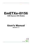
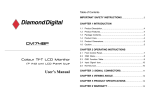
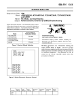
Rev.1.01
Dec 16, 2011
R20UT0456EJ0101
Operating Environment of the Included Software Products
R0E521500MCU00 Release Notes - Read this before using this product Renesas Solutions Corp.
This document contains the information necessary for using this product. Be sure to read this before using the product.
Introduction
The operating environments of the included software products are shown below.
(1) Operating environment of the host machine (Windows® XP)
Host machine
IBM PC/AT compatibles
OS
Windows® XP 32-bit editions *1 *2
CPU
Pentium 4 running at 1.6 GHz or more recommended
Memory
1 Gbyte plus 10 times the file size of the load module or larger recommended
The R0E521500MCU00 is an MCU unit for the R8C/5x Series of Renesas 16-bit MCUs.
(2) Operating environment of the host machine (Windows Vista® or Windows® 7)
Host machine
IBM PC/AT compatibles
Windows Vista® 32-bit editions *1 *3
OS
Windows® 7 32-bit editions / 64-bit editions *1
Pentium 4 running at 3 GHz or
CPU
Core 2 Duo running at 1 GHz or more recommended
2 Gbytes plus 10 times the file size of the load module or larger recommended (32-bit
editions)
Memory
3 Gbytes plus 10 times the file size of the load module or larger recommended (64-bit
editions)
*1 Windows and Windows Vista are either registered trademarks or trademarks of Microsoft Corporation in the
United States and/or other countries.
*2 The 64-bit editions of Windows® XP are not supported.
*3 The 64-bit editions of Windows Vista® are not supported.
Product outline
This product consists of the following two products.
(1) MCU unit: R0E521500MCU00
This is an MCU unit (board) for the R8C/5x Series.
(2) M16C R8C E100 Emulator Software
The Included software is stored in the CD-ROM.
- M16C R8C E100 Emulator Debugger
This is a control software specifically designed for the R8C E100 Emulator to control the R0E521500MCU00
emulator.
For the Latest Information
Installing the Included Software Products
Visit our website (URL below). Please use this website providing the latest information of Renesas tool products.
Furthermore, the latest version of the included software (emulator debugger and evaluation version C compiler package)
can be downloaded.
http://www.renesas.com/tools
After inserting the included CD-ROM into the host machine’s CD-ROM drive, the installation window will open. Select the
product to be installed and click “Install” button.
Before installing the software, check that the High-performance Embedded Workshop is not started up on the PC
environment you use and that any Renesas emulator is not connected to the PC.
Setup Guide
1. Check the contents
▼
2. Install emulator debugger
▼
3. Register your R0E521500MCU00
▼
4. Setup hardware and turn on the emulator
▼
Startup the High-performance Embedded
Workshop and the emulator debugger.
▼
6. For usage of each product
5.
* If using Windows® 7, Windows Vista® or Windows® XP as the host machine OS, have the software installed by
someone of administrator access level. Installation cannot be completed by users with lower access level status.
For details, refer to...
>> “Package Components”
When a PC Running Windows Vista® Cannot Communicate with the Emulator
>> “Installing the Included Software Products”
After connecting the E100 emulator to the host machine, power on the emulator. Then open the Device Manager and select
Renesas USB Driver, and open its [Properties] dialog box. On [General] tab you can check the [Device status]. If it does not
show “This device is working properly.”, follow the procedure listed below to install the USB driver manually.
>> R0E521500MCU00 User’s Manual
“User Registration”
1. Double click dpinst.exe stored in the attached CD-ROM, in a directory:
<drive name>\e100_m16c\drivers\for_32bit\Renesas_E_Series_USB, to execute dpinst.exe.
2. You'll see a [User Account Control] dialog box titled "An unidentified program wants access to your computer" and
stating "Don't run the program unless you know where it's from or you've used it before." To continue the installation,
click [Allow].
*dpinst.exe is a driver package installation utility provided by Microsoft.
3. When [Device Driver Installation Wizard] appears, click the [Next] button.
4. A dialog box appears asking "Would you like to install this device software?" Then, click the [Install] button.
5. When the driver installation is complete, click the [Finish] button on the [Device Driver Installation Wizard].
>> R0E521500MCU00 User’s Manual
“Chapter 2. Setup”
>> R0E521500MCU00 User’s Manual
“Chapter 3. Tutorial”
>> R0E521500MCU00 User’s Manual
“Chapter 5. Debugging Functions”
Package Components
Check to see if your product package contains all of the following items before using the product.
1
R0E521500MCU00 MCU unit
2
R0E521500MCU00 Release Notes (this document)
R0E521500MCU00 Release Notes (Japanese)
3
Repair Request Sheet (English)
Repair Request Sheet (Japanese)
4
CD-ROM - M16C R8C E100 Emulator Software
If any of these items are missing or found faulty, please contact your local distributor.
Precautions for Using the Included Software Products
1
1
1
1
1
1
Release notes are installed during the software installation. Read it before using the software product.
*
Electronic manuals and release notes are included in the software package. To view electronic documents, download
Adobe Reader from Adobe Systems website (http://www.adobe.com/). Adobe and Reader are either registered
trademarks or trademarks of Adobe Systems Incorporated in the United States and/or other countries.
To Contact Us
For technical information on this product and the emulator debugger, contact us from the following URL.
http://www.renesas.com/inquiry
1/2
Applicable MCU Groups
(5)
The R0E521500MCU00 is available for the R8C/5x Series MCUs by using with the following converter boards.
Converter board
R0E53054ECFK60
(PLQP0048KB-A)
R0E53036ACFK40
(PLQP0064KB-A)
Applicable MCU Groups
: R8C/54E, 54F, 54G and 54H Groups
: R8C/56E, 56F, 56G and 56H Groups
*1: Bit 0 of the protect register (PRCR, address 00007h) controls whether to enable or disable writing to the PCLKR1
register on the actual MCU.
Restrictions on Using the Emulator
*2: Bit 5 of the protect register (EPRR, address 0025Fh) controls whether to enable or disable writing to the PCLKR1
register on this product.
This product has the following restrictions. Note that these restrictions apply only when using the emulator. When using an
actual MCU, check the hardware manual of the MCU. For restrictions other than listed below, check the
R0E521500MCU00 User’s Manual.
(1) Note on the Processor Mode Register 0 (PM0):
The R8C/5x Group actual MCU and this product differ in the initial value of the processor mode register 0 (PM0,
address 0004h).
This product: 02h
R8C/5x Group actual MCU: 00h
When using this product, be sure that bit 1 of PM0 remains "1" as initially set. If bit 1 of PM0 is cleared to "0", the
emulator will become uncontrollable.
Also, when using this product, please be sure that only a bit-manipulating instruction is used for a write to bit 3
(PM03) of processor mode register 0 (PM0, address 0004h). If this bit is inadvertently written to, shut down the power
to the emulator and restart.
(2)
Note on the Low-current-consumption Read Mode:
Do not stop the user program during the low-current-consumption read mode. If the user program is halted during the
low-current-consumption read mode, values in the flash ROM area cannot be read correctly until the MCU is reset
thereafter.
(3)
Note on Non-maskable Interrupts:
When using this product, do not use the non-maskable interrupts listed blow. If one of these non-maskable interrupts
contends with another interrupt, the occurrence of the intended non-maskable interrupt may delay. Note, however,
that this does not apply for the actual MCU.
(1) Watchdog timer
(2) Oscillation stop detection
(3) Voltage monitor 1
(4) Voltage monitor 2
(4)
Note on Peripheral Clock Select Register (PCLKR1):
In order to rewrite the1 peripheral clock select register 1 (PCLKR1, address 0000Fh)
while using this product, you
need to first set bit 0* of the protect register (PRCR, address 00007h) and bit 5*2 of the protect register (EPRR,
address 0025Fh) to “1”. Once the rewrite on PCLKR1 is complete, set bit 0 of PRCR and bit 5 of EPRR back to “0”*3.
The actual MCU does not have the protect register EPRR, the setting of which, however, does not affect the actual
operation.
*3: When using this product, note that the PCLKR1 register is rewritable if bit 5 of EPRR is “1” even if bit 0 of PRCR is
“0”. Make sure to set bit 5 of EPRR back to “0”.
(6)
Note on the PLL Clock:
When using this product, be aware that the high-speed on-chip oscillator cannot be used as the clock source for the
PLL frequency synthesizer.
(7)
Note on the Low-speed On-chip Oscillator Oscillation Stop Bit (CM14):
When the low-speed on-chip oscillator is selected for the operating clock, the low-speed on-chip oscillator oscillation
stop bit (CM14, bit 4 at address 0009h) in the actual MCU is disabled from being set to "1" (= stop). In this product,
however, this bit can be set to "1" (= stop).
(8)
Note on Oscillation Stop Detection at WAIT Time:
When using this product, leave oscillation stop detection turned off during WAIT mode. This is because this function
may not work normally during WAIT mode.
(9)
Note on the timer RB2:
To use the output event of timer RB2 along with the event link controller (ELC) in this product, follow the procedure
described below.
(1) If interrupt handling based on timer RB2 is unnecessary, set bits 2–0 (IVL2–IVL0 bits) of TRB2IC_0 and 1
registers to 000b to disable interrupts.
(2) Set up the DTC-related registers so that DTC transfers based on underflow of timer RB2 are executed. At this
time, be sure the repeat mode is selected and that the source and destination registers are mapped to a free
RAM area, etc. where they can be accessed without affecting the system.
(3) Set bit 7 (TRBIE) of TRBIR register to "1" to enable the timer RB2 interrupt.
(10) Note on the Pin Assignment Select Register (PMCSEL)
When the 48-pin product is selected, the values for the pin assignment select bit are different between the R8C/5x
Group actual MCU and this product.
Note on Program Stoppage and Hardware Breaks:
If an operation to stop the program is performed or a hardware break occurs in the emulator debugger, be aware that
the program does not stop until after the period described below ends.
- Providing that interrupts are enabled, a period from when a request for an interrupt whose priority level
(selected by a register bit) is higher than the IPL is generated till when the interrupt routine is entered
48-pin product standard pin assignment:
48-pin product communication function priority pin assignment:
This product
PMCSEL=000b
PMCSEL=001b
R8C/5x Group actual MCU
PMCSEL=011b
PMCSEL=100b
(11) Note on Power Supply Voltage of the User System
To use this product, the power supply voltage range of the user system must be 2.7[V] ≤ Vcc ≤ 5.5[V]. A voltage of
2.7 [V] or lower makes the emulator uncontrollable.
Note: If the above interrupt request is for an interrupt nested in another or disabled by clearing the I flag to "0", it will
take a longer time than otherwise before the interrupt routine is entered. In this case, the timing with which the
program is halted is delayed that much.
Note, however, that this does not apply to software breaks.
2/2