1
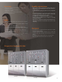
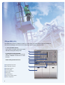
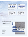
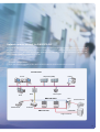
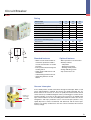
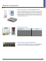
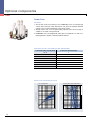
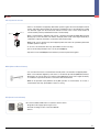
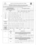
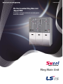
www.lsis.biz
SF6 Gas Insulated Ring Main Unit
RMU
A Compact switchgear solution for secondary power
distribution networks.
Super Solution
Ring Main Unit
Ring Main Unit
The best solution for Power Distribution
Contents
4
Features
6 Configurations
15 Optional components
8 Intelligent application
20 Operational sequence
10 Main characteristics
21 Dimensions
Detailed characteristics for each
22 Quality assurance
RMU
A Compact Switchgear Solution for Secondary Distribution
(Ring Main Unit Up to 24kV, SF6 - Insulated)
Susol RMU is enable to install on medium voltage distribution network and mainly used
for protection of transformers in compact substations. It is used for medium voltage
distribution in compact substations, small buildings, residential housing complex, large
shopping malls, airports, wind power, etc. comprising medium voltage networks.
The concept of Susol RMU is offering a choice of other switch-fuse combination or
circuit breaker with relay for protection of the transformer.
function
[
12 Load Break Switch
13 Circuit Breaker
14 Fuse combination Switch
14 Cable compartments
]
RMU is the solution to meet your medium
voltage power distribution line needs.
Susol RMU is a compact ring main unit combining all MV functional units to enable to
supply and protect transformers on the secondary distribution network.
Susol RMU can be supplied in various and different configurations suitable for most
switching applications in 12/17.5/24 kV distribution networks.
4
Technology
Durability and usefulness
�Metal enclosed unit for Indoor installation and type tested.
�Insulated by SF6 Gas.
�Maintenance free and easy installation.
�Independent of climate.
�ON-OFF-Earth, three position load break switch.
�Recyclable materials used.
�Metal enclosed tank is hermetically sealed, it means this is
independent of environmental effects such as dirt, small insects,
moisture and so on.
�Load break switch operating is possible in the front of Ring Main
Unit.
�All switching operations can be made safely to personnel
because of interlocking system that operates automatically
according to the switch position by the operator.
�No requirement of recharging SF6 gas until its service life.
�Remote operation available in case of using motor operating
mechanism and FRTU.
�HRC power fuse will trip the mechanism automatically by a fuse
striker pin connected to mechanism in the event of fault
happening.
Safety
�Approachable and operable safely in the presence of power in
the cables.
�Clear indication of operation status via mimic diagram on front
panel.
�Fully automatic interlocking system.
- Operation is only possible in case door is totally closed.
- Fuse compartment is only accessible when Load break
switch is earthed.
- Voltage detector to check whether cables are lined or not.
�Rupture disk is designed to protect devices in case of
emergency like gas expansion.
�Internal arc withstand is tested for the operator safety in case of
accident current occur. (21kA/1s, without SF6 Gas)
Saving cost
�No maintenance is required other than replacement of HRC
Power Fuse after installation.
�Compact design that requires minimum space to install and
operate locally is main advantage especially where the space is
limited.
�No additional costs for replacement because of long service life.
�Materials can be recycled after the end of its service life.
CB type (LCL) & Fuse type (LFL) RMU
LCL type
LFL type
5
CB type RMU (LCL)
Susol RMU offers a choice of solutions to make 2,3 or 4 directional connections with line protection by 630A CB,
with network switching by switch-disconnectors with integrated power supply telecontrol device
�L : LBS (Load Break Switch)
Three position Load Break Switch below 630A
with disconnecting and earthing switch
�C : VCB (Vacuum Circuit Breaker)
200A vacuum circuit-breaker for transformer
protection 400/630A circuit-breaker for feeder
protection
�Cable bushing horizontal in front
�
�
�
�
�
�
�
� Ring S/W Earth operation
� Circuit Breaker operation
�
� Ring S/W operation
� Pressure gauge
� Earth S/W operation
� Name plate
� Voltage Indicator
� Disconnector S/W operation
� Cable compartment
6
�
Configurations
�Information of model name
L : LBS
(Load Break Switch)
L
L : LBS
(Load Break Switch)
F/C
L
F : Load break switch-Fuse combination
C : Vacuum Circuit breaker with Disconnecting switch
No. of LBS
L
F/C
No. of F/C system
�Diagram, standard types
LCL ( 2L1C )
LFL ( 2L1F )
Fuse type RMU (LFL)
LFL-model of Susol RMU offers the solution of transformer protection by fuses
�L : LBS (Load Break Switch)
Three position Load Break Switch below 630A
with disconnecting and earthing switch
�
�F : Switch Fuse (Load Break Switch-Fuse
combination)
200A switch-fuse combination for transformer
protection
�Cable bushing horizontal in front
�
�
�
�
� Ring S/W Earth operation
� T-off operation
� Ring S/W operation
�
�
� Pressure gauge
� Voltage Indicator
�
� Cable compartment
� Fuse compartment
� Name plate
7
Intelligent application
Equipped with RTU (Remote Terminal Unit), the Susol RMU
switchgear can implement intelligent application. Connecting all
Susol RMU with communication network, it enables to monitor
and control the switchgear remotely.
�RTU (Remote Terminal Unit)
The Remote Terminal Unit(RTU) collects data from field instruments &
sensors and transmits the information to the Supervisory Control and Data
Acquisition System (SCADA) installed in a central control room through
communication systems and lines, and receives control commands from the
telemeter telecontrol system to conduct online controls in real time.
8
Network remote control for DAS/SCADA
Equipped with RTU (remote termination unit), the Susol RMU switchgear can implement intelligent application. Connecting all
the IRMUs by a communication network, it enable to monitor and control the switchgear remotely, locate and isolate fault
automatically as well as the system recovery. This will dramatically reduce the affected area and duration of blackout, and
realize the high reliability and excellent power quality.
�System configuration
Susol RMU equipped with RTU provides all the functions needed to operate the MV network in real time
Control Center
Server
OTS
Dispatcher (MMI)
DAU
Hard Copier
RMU with RTU
Power Plant
Printer
RTU
Small Customer
Substaion
RMU with RTU
Pol Switch
Large Customer
9
Main characteristics
Rating
Rated voltage
kV
12
17.5
24
Rated frequency
Hz
50/60
50/60
50/60
Rated power frequency withstand voltage
kV
28
38
50
Rated lightning impulse withstand voltage
kV
75
95
125
A
630
630
630
Rated current main busbars
Rated short-time withstand current (3s)
kA
21
21
21
Rated short-circuit making current
kA
54.6
54.6
54.6
kA
21
21
21
Psi.G
5
5
5
Internal arc fault current (1s, AFAL)
Rated SF6 gas pressure
Standards
LCL type
Susol RMU meets international standards such as following
Standard
IEC 62271-1
IEC 62271-100
IEC 62271-102
IEC 62271-103
IEC 62271-105
IEC 62271-200
Description
High-voltage switchgear and controlgear
Part 1: Common specifications
High-voltage switchgear and controlgear
Part 100: Alternating-current circuit-breakers
High-voltage switchgear and controlgear
Part 102: Alternating current disconnectors and earthing switches
High-voltage switchgear and controlgear
Part 103: Switches for rated voltages above 1 kV up to and including 52 kV
High-voltage switchgear and controlgear
Part 105: Alternating current switch-fuse combinations
High-voltage switchgear and controlgear
Part 200: AC metal-enclosed switchgear and controlgear for rated
voltages above 1 kV and up to and including 52 kV
Environment conditions
LFL type
Conditions
Temperatures
Altitude
Humidity
Description
- The cubicles must be stored and installed in a dry area free from dust and
with limited temperature variations.
- For stocking : from -40 °C to +60 °C
- For working : from -25 °C to +40 °C
- Other temperature, consult us.
- Altitude for installation above sea level : under 1,000 m
- Relative humidity : max. 95 %
Additional information
Conditions
Global options
User options
Protection index
10
Description
- Manometer
- VIS(Voltage Indication Systems)
- All cable covers with interlock system
- Fuse cover with interlock system
- Internal arc exhausting box for 21kA/1s
- Remote operating system for Load break switch
- Remote operating system for fuse combination switch
- Remote operating system for circuit breaker
- OCR(Over Current Relay) operating Circuit breaker
- Padlock system (key locking devices)
- IP3X on front face, IP67 for SF6 tank
Types and diagrams
Dimension (W×H×D), mm
1. standard type
LFL (2L1F)
LCL (2L1C)
1030×1400×752
1030×1400×752
2. Load break switch combinations
LLL (3L)
LLLL (4L)
1030×1400×752
LLLLL (5L)
1390×1400×752
1720×1400×752
3. Transformer protection by circuit breakers
LC (1L1C)
LCCL (2L2C)
LLCL (3L1C)
755×1400×752
1450×1400×752
1390×1400×752
LLCCL (3L2C)
1780×1400×752
4. Transformer protection by fuses
LF (1L1F)
LFFL (2L2F)
755×1400×752
1500×1400×752
LLFL (3L1F)
1360×1400×752
LLFFL (3L2F)
1830×1400×752
11
Load Break Switch
Rating
Rated voltage
kV
12
17.5
24
Rated frequency
Hz
50/60
50/60
50/60
Rated power frequency withstand voltage
kV
28
38
50
Rated lightning impulse withstand voltage
kV
75
95
125
A
630
630
630
Rated current
Rated short-time withstand current (3s)
kA
21
21
21
Rated short-circuit making current
kA
54.6
54.6
54.6
Electrical endurance class
E3
E3
E3
Mechanical endurance class
M1
M1
M1
Earthing switch
Rated short-time withstand current (3s)
kA
21
21
21
Rated short-circuit making current
kA
54.6
54.6
54.6
Electrical endurance class
E1
E1
E1
Mechanical endurance class
M1
M1
M1
* M1: 1,000 Mechanocal Operations
Standard features
Optional features
�Three position load break switch
with disconnector and earthing
switch
�Operating mechanism with two
separate shaft for load and earthing
function
�Switch position indication for LBS
and ES
�Cable bushing horizontal in front
with integrated capacitor for voltage
indication
�Motor operation for load break
switch
�Auxiliary switches
- Load break switch position
- Earthing switch position
�Voltage indicating system
�Short circuit and earth fault indicator
Operation of 3-Position Load Break Switch
Main close
12
Open
Earth
Circuit Breaker
Rating
Rated voltage
kV
12
17.5
24
Rated frequency
Hz
50/60
50/60
50/60
Rated power frequency withstand voltage
kV
28
38
50
Rated lightning impulse withstand voltage
kV
75
95
125
A
200/630
200/630
200/630
Rated current
Rated short-time withstand current (3s)
kA
21
21
21
Rated short-circuit making current
kA
54.6
54.6
54.6
Electrical endurance class
E2
E2
E2
Mechanical endurance class
M1
M1
M1
630
630
630
Disconnector and Earthing switch
Rated current
A
Rated short-time withstand current (3s)
kA
21
21
21
Rated short-circuit making current
kA
54.6
54.6
54.6
Electrical endurance class
E1
E1
E1
Mechanical endurance class
M1
M1
M1
* M1: 2,000 Mechanocal Operations
Standard features
Optional features
�200 A vacuum circuit-breaker for
transformer protection or 630 A
vacuum circuit-breaker for feeder
protection
�Three position disconnecting and
earthing switch
�Switch position indication for CB
and DS/ES
�Cable bushing horizontal in front
�Interlocking between CB and
DS/ES
�Motor operation for circuit breaker
�Auxiliary switches
- CB position
- Disconnector position
- Earthing switch position
�Voltage indicating system
�Trip coil and close coil
Vacuum interrupter
Current
path
Driving force
on the high
current ARC
ARC
In the closed position, normal current flows through the interrupter. When a fault
occurs and interruption is required, the contacts are quickly separated. The arc
drawn between the surfaces of contact is rapidly moved around the slotted
contact surface by self induced magnetic effects, preventing gross contact erosion
and the formation of hot spot on the surface. The arc burns in an ionized metal
vapor, which condenses on the surrounding metal shield. At current zero the are
extinguishes and vapor production ceases. The metal vapor plasma is very
rapidly dispersed, cooled, recombined, and deionized, and the metal vapor
products are quickly condensed so that the contacts withstand the transient
recovery voltage.
13
Switch-fuse combination
Rating
Rated voltage
kV
12
17.5
24
Rated frequency
Hz
50/60
50/60
50/60
Rated power frequency withstand voltage
kV
28
38
50
Rated lightning impulse withstand voltage
kV
75
95
125
A
200
200
200
Rated current
Electrical endurance class
E1
E1
E1
Mechanical endurance class
M1
M1
M1
5
5
5
Earthing switch
Rated short-time withstand current (1s)
kA
Rated short-circuit making current
kA
13
13
13
Electrical endurance class
E1
E1
E1
Mechanical endurance class
M1
M1
M1
* M1: 1,000 Mechanocal Operations
Standard features
Optional features
�Three position switch-fuse
combination with earthing switch
�Switch position indication for switchfuse combination and earth switch
�Cable bushing horizontal in front
�Fuse holder for DIN type fuse-links
�Fuse-link rating
- 12/17.5kV: max. 100 A, LSIS DIN
type fuse-link
- 24kV: max. 75 A, LSIS DIN type
fuse-link
�Automatically tripped to protect from
fault current when a fuse is blown
�Motor operation for switch-fuse
combination
�Auxiliary switches
- LBS position
- Earthing switch position
- Fuse blown status
�Voltage indicating system
�Trip coil
Cable compartment
6
7
8
9
3
1
2
5
14
4
1. Screened body
2. Inner screen
3. Compressing lug
4. Stress cone adapter
5. Earthing eye and lead
6. Theaded pin
7. Rear plug with test point
8. Test point
9. Conductive end cap
Optional components
OCR (Current Relay) : CT powered protection relay
This relay is self-powered relay by the CT in Susol RMU and can be set with
definite time and inverse time characteristics for short circuit, overload and earth
fault current. Parameter setting can be done in different user-friendly ways,
computer controlled or with HEX switches on the front. The relay is also
provided with a digital memory for the storage of the most recent tripping values.
This relay has proven to be a reliable and widely accepted method of protection
in worldwide distribution networks.
CT(Current transformer )
Max. system voltage
kV
0.6
Primary current
A
7.2~230.4
Secondary current
A
0.075
Rated burden
VA
Accuracy class
Short time-current
Rated frequency
0.1
10P80
KA/1s
Hz
20
50/60
Voltage indicator lamps (Voltage Detector)
It is a device to check the presence or absence of voltage in the cables. It is
conforming to IEC standard 61958. Push button type LED voltage indicator is
provided and lamp power is supplied by bushing type capacitive dividers.
15
Optional components
Power Fuse
Features
1. The LS HRC Power Fuses belong to the PRIME MEC series. It interrupts high
currents before the peak value and therefore cuts down the required withstand
capacity of the associated equipment on the electric system.
2. Though small in size, it has a high breaking capacity and its enclosed type is
suitable for use inside of the panel board.
3. PRIME-MEC fuses are equipped with striker pins for trip indicators as well as for
inflicting impulse to trip link of related load break switches.
Selection of fuses: According to IEC 60787(24kV)
Transformer rating capacity (kVA)
Power Fuse rated current (A)
36 ~75
5
75 ~ 157
10
172 ~ 358
20
258 ~ 538
30
464 ~ 965
40
598 ~ 1246
50
745 ~ 1554
63
1000 ~ 1983
75
Note) Please ask fuse maker for optimum selection of fuses.
Power fuse characteristic curve
Cut-off characteristic
Pre-arcing time-current characteristics
1000
800
600
1000
800
600
5A
200A
400
400
10A
160A
200
20A
125A
100
80
60
30A
100A
40A
75A
50A
63A
100
80
60
200A
40
125A
160A
100A
20
75A
10
8
6
63A
4
40A
50A
30A
2
20A
10A
1
0.8
0.6
5A
0.4
20
10
8
6
4
2
1
0.8
0.6
0.4
0.2
0.2
0.1
0.08
0.06
0.1
0.08
0.06
0.04
0.04
0.02
0.02
0.01
Prospective breaking current (rms:A) →
4000
6000
8000
10000
2000
400
600
800
1000
200
40
60
80
100
20
4
6
8
10
2
40
100
6
8
10
20
2
4
0.2
0.6
0.8
1
0.4
0.06
0.08
0.1
0.04
0.02
0.01
Prospective breaking current(rms:kA) →
16
40
Operating time(sec.) →
Cut-off current(peak value:kA) →
200
Optional components
Optional components for CB mechanism
CB Mechanism
�
�
�
�
�
� SHT coil for CB
SHT is a control device which trips a circuit breaker from remote place, when applying
voltage continuously or instantaneously over 200ms to coil terminals
� Closing coil for CB
It is a control device which closes a circuit breaker, when the voltage is applied
continuously or instantaneously over 200ms to the coil terminals
� MTD (Magnetic Tripping Device)
It is a control device which trips a circuit breaker from the OCR, when the short circuit
current or overload current occurred
*Tripping time could be set by the OCR t-settings
� Auxiliary switch for CB
It is a contact used to monitor ON/OFF position of circuit breaker from remote place
*Standard ON charge 5a5b/ Standard OFF charge 5a5b
� Geared motor for CB
Charge the closing spring of a circuit breaker by the external power source. Without the
external power source, charge manually.
*Operating voltage range → 85%~110% Vn
17
Optional components
Optional components for LBS/F-LBS mechanism
LBS Mechanism
F-LBS Mechanism
�
�
�
�
� Auxiliary switch for LBS/F-LBS
It is a contact used to monitor ON/OFF position of Load break switch/ fuse combination
switch from remote place
*Standard ON/OFF/EARTH for each position
� Geared motor for LBS mech
Charge the closing and opening spring of a load break switch by the external power
source. Without the external power source, charge source. manually.
*Operating voltage range → 85%~110% Vn
� Geared motor for F-LBS mech
Charge the closing spring of a fuse combination switch by the external power source.
Without the external power source charge manually source. source, manually.
*Operating voltage range → 85%~110% Vn
� SHT coil for F-LBS mech
SHT is a control device which trips a fuse combination switch from remote place when
applying voltage continuously or instantaneously place, over 200ms to coil terminals
18
CB-Trip alarm contact
AL2, 1a
AL1, 1a
� When a circuit breaker is tripped by OCR which operates against the fault current(Over Current
Relay), Trip Alarm switch provides the information regarding the trip of circuit breaker by sending
the electrical signal from the mechanical indicator on main cover of main circuit breaker or
internal auxiliary switch. (Installed at the inside of circuit breaker)
�When a circuit breaker is tripped by fault current, a mechanical trip indicator(MRB, Manual Reset
Button) pops out from the main cover and the switch(AL) which sends control signal electrically is
conducted to output the information occurred from fault circuit breaker
�MRB and AL can be operated only when tripped by OCR, but doesn’t be operated by Off button
and OFF operation of trip coil.
�To re-close a circuit breaker after a trip, press MRB to reset it for closing.
�2pcs of electrical trip switch(AL1, AL2, 1a) are provided(Option)
�Trip alarm contact and MRB(Manual reset button) need to be purchased together
MRB (Manual Reset Button)
�It is a function which resets a circuit breaker manually when a circuit breaker is tripped by OCR.
�When a circuit breaker tripped by fault current, a mechanical trip indicator(MRB,Manual Reset
Button)pops out from the main cover and the switch(SDE)which sends control signal electrically
is conducted to ouput the information occurred from fault circuit breaker.
�MRB can be operated only by OCR but not by OFF operation of circuit breaker, To re-close a
circuit breaker after a trip, press MRB to reset it for closing.
EFI (Earth fault indicator)
EFI can be installed at RMU frame or anywhere customer wants.
�Single Phase AC supply split core type sensor
�Automatic resetting function on AC 220~230V3Ph
�3Phase
19
Operational sequence
Operational sequence for CB
Closing start
Closing operation finish
Opening signal
Closing signal
Opening start
Power ’ON’ Motor charging start (5s)
Opening operation finish
MOTOR
CLOSING SPRING
OPENING SPRING
CLOSING COIL
SHUNT COIL
MAIN CONTACTS
Closing time
Opening time
Operational sequence for LBS
Opening signal
Motor charging start (5s)
Closing operation finish
Closing start
Closing signal finish Motor charging start
Opening start
Opening operation finish
MOTOR
CLOSING, OPENING SPRING
MAIN CONTACTS
Closing time
Opening time
Operational sequence for F-LBS
Closing operation finish
Opening signal
Closing start
Opening start
Closing signal Motor charging start
Opening operation finish
MOTOR
CLOSING SPRING
OPENING SPRING
SHUNT COIL
MAIN CONTACTS
Closing time
20
Opening time
Dimensions
LCL (2L1C)
950
26.5
1400
600
734
Mounting hole
4- 18
587
A-view
52.5
1030
27.2
724.8
752
27.2
724.8
752
A
LFL (2L1F)
950
26.5
1400
600
734
Mounting hole
4- 18
52.5
587
A-view
1030
A
21
Quality assurance
Certified quality
: STL(The Short-Circuit Testing Liaison, KERI), ISO 9001, ISO 14001
LSIS has integrated a functional organization into each of its units, the main purpose of which is to check
quality and ensure the adherence to standards.
Routine quality check
While producing Susol RMU, various routine tests are taken for product capacity. Tested items are as
shown follows.
�Filling pressure check
�Tightness check
�Manual and motor operation check
�Dielectric check
�Contact resistance check
Ordering Information
LFL
24
62
12
Type
Operation
Code
Rated Voltage
Code
Rated Current
LFL
Manual
B
24kV
12
(Main/T-OFF)
LCL
AC 110V
A1
17.5kV
17
630/630A
LLL
AC 220V
A2
12kV
24
630/400A
LLLL
DC 110V
D1
630/200A
62
LCCL
DC 220V
D2
630/-A
60
LFFL
LLCL
LLFL
22
B
D
BIL
Code
125kV BIL
12
66
95kV BIL
09
64
75kV BIL
07
Code
DIN Type Bushing : D
� For your safety, please read user's manual thoroughly before operating.
� Contact the nearest authorized service facility for examination, repair, or adjustment.
� Please contact a qualified service technician when you need maintenance.
Do not disassemble or repair by yourself!
Safety Instructions
� Any maintenance and inspection shall be performed by the personnel having expertise concerned.
ⓒ 2012. 10 LSIS Co.,Ltd. All rights reserved.
� HEAD OFFICE
LS-ro 127 (Hogye-dong) dongan-gu Anyang-si
Gyeonggi-do Korea
Tel. (82-2)2034-4887, 4873, 4918, 4148
Fax. (82-2)2034-4648
www.lsis.biz
� Global Network
�LSIS (Middle East) FZE �
�Dubai, U.A.E.
Address: LOB 19 JAFZA VIEW TOWER Room 205, Jebel Ali Freezone P.O. Box 114216, Dubai, United Arab Emirates
Tel: 971-4-886 5360 Fax: 971-4-886-5361 e-mail: [email protected]
�Dalian LSIS Co., Ltd. �
�Dalian, China
Address: No.15, Liaohexi 3-Road, Economic and Technical Development zone, Dalian 116600, China
Tel: 86-411-8273-7777 Fax: 86-411-8730-7560 e-mail: [email protected]
�LSIS (Wuxi) Co., Ltd. �
�Wuxi, China
Address: 102-A , National High & New Tech Industrial Development Area, Wuxi, Jiangsu, 214028, P.R.China
Tel: 86-510-8534-6666 Fax: 86-510-522-4078 e-mail: [email protected]
� CHEONG-JU PLANT
Cheong-Ju Plant #1, Song Jung Dong, Hung Duk Ku,
Cheong Ju, 361-720, Korea
�LSIS-VINA Co., Ltd. �
�Hanoi, Vietnam
Address: Nguyen Khe - Dong Anh - Ha Noi - Viet Nam
Tel: 84-4-882-0222 Fax: 84-4-882-0220 e-mail: [email protected]
�LSIS-VINA Co., Ltd. �
�Hochiminh , Vietnam
Address: 41 Nguyen Thi Minh Khai Str. Yoco Bldg 4th Floor, Hochiminh City, Vietnam
Tel: 84-8-3822-7941 Fax: 84-8-3822-7942 e-mail: [email protected]
�LSIS Shanghai Office �
�Shanghai, China
Address: Room 32 floors of the Great Wall Building, No. 3000 North Zhongshan Road, Putuo District, Shanghai, China
Tel: 86-21-5237-9977 Fax: 89-21-5237-7189 e-mail: [email protected]
�LSIS Beijing Office �
�Beijing, China
Address: B-Tower 17FL.Beijing Global Trade Center B/D. No.36, BeiSanHuanDong-Lu, DongCheng-District,
Beijing 100013, P.R. China
Tel: 86-10-5825-6025,7 Fax: 86-10-5825-6026 e-mail: [email protected]
�LSIS Guangzhou Office �
�Guangzhou, China
Address: Room 1403, 14/F, New Poly Tower, No.2 Zhongshan Liu Road, Guangzhou 510180, P.R. China
Tel: 020-8326-6754 Fax: 020-8326-6287 e-mail: [email protected]
�LSIS Chengdu Office �
�Chengdu, China
Address: Room 1701 17Floor, huamin hanjun internationnal Building, No1 Fuxing Road Chengdu, 610016, P.R. China
Tel: 86-28-8670-3201 Fax: 86-28-8670-3203 e-mail: [email protected]
�LSIS Qingdao Office �
�Qingdao, China
Address: Room 2001,20/F,7B40, Galaxy Building, No.29 Shandong Road, Shinan District, Qingdao 266071, P.R. China
Tel: 86-532-8501-6058 Fax: 86-532-8501-6057 e-mail: [email protected]
�LSIS NETHERLANDS Co.Ltd �
�Schiphol-Rijk, Netherlands
Address: 1st. Floor, Tupolevlaan 48, 1119NZ,Schiphol-Rijk, The Netherlands
Tel: 31-20-654-1420 Fax: 31-20-654-1429 e-mail: [email protected]
Specifications in this catalog are subject to change without notice due to
continuous product development and improvement.
2012. 10
�LSIS Gurgaon Office �
�Gurgaon ,India
Address: 109 First Floor, Park Central, Sector-30, Gurgaon- 122 002, Haryana, India e-mail: [email protected]
Susol Ring Main Unit (E) 2012. 10/(01) 2012. 10 Printed in Korea STAFF