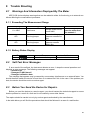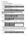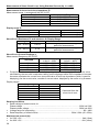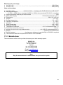
1
OPERATING MANUAL SHORT-CIRCUIT LOOP IMPEDANCE METER MZC-310S SONEL SA ul. Wokulskiego 11 58-100 Świdnica Version 3.4 TABLE OF CONTENTS 1 PREFACE ...................................................................................................... 5 2 INTRODUCTION ............................................................................................ 6 3 SAFETY ......................................................................................................... 6 4 DEVICE DESCRIPTION AND ITS FUNCTIONALITY ................................... 6 4.1 4.2 4.3 4.4 MZC-310S CHARACTERISTICS.................................................................... 6 STANDARD ACCESSORIES ........................................................................... 7 OPTIONAL ACCESSORIES ............................................................................ 7 TERMINALS AND KEYS LAYOUT .................................................................... 8 4.4.1 4.4.2 4.5 4.6 4.7 Terminals .......................................................................................................8 Keyboard ........................................................................................................9 GRAPHICAL DISPLAY PANEL (LCD) ............................................................ 10 BUZZER .................................................................................................... 11 TEST LEADS ............................................................................................. 12 5 STORAGE .................................................................................................... 13 6 BEFORE YOU START................................................................................. 13 7 OPERATIONS .............................................................................................. 14 7.1 7.2 7.3 7.4 7.5 7.6 7.7 7.7.1 7.7.2 7.7.3 7.7.4 7.7.5 7.7.6 7.7.7 7.7.8 7.7.9 7.8 7.9 7.9.1 7.9.2 7.9.3 PREPARING THE DEVICE FOR W ORK.......................................................... 14 POWER SUPPLY VOLTAGE MONITORING .................................................... 15 BATTERY REPLACEMENT ........................................................................... 15 CONDITIONS FOR PERFORMING TESTS AND OBTAINING CORRECT RESULTS 16 DEVICE CONNECTION DIAGRAMS ............................................................... 17 MEASUREMENT OF ALTERNATING VOLTAGE ............................................... 22 SHORT-CIRCUIT LOOP MEASUREMENT ...................................................... 22 Measurement of Network Voltage and Frequency .......................................23 Changing The Network Rated Voltage ......................................................... 23 Displaying All Measurement Results Or The Main Result Only.................... 23 Displaying The Measurement Results In Terms of Impedance or ShortCircuit Current .............................................................................................. 24 Measurement of Touch Voltage UST And Touch Shock Voltage UT .............24 Selection of Test Cables Length (For Measurements Using Two-Pole Method) ........................................................................................................25 Results Display ............................................................................................ 25 Measurement of Short-Circuit Loop Parameters Using Two-Pole Method ...26 Measurement of Short-Circuit Parameters By the Four-Pole Method ..........26 MEASUREMENT OF EARTHING RESISTANCES .............................................. 26 SAVING THE MEASUREMENT RESULTS ....................................................... 28 Storing Measurement Results In The Memory .............................................29 Memory Browsing ........................................................................................ 29 Erasing the memory ..................................................................................... 30 3 7.10 MENU ....................................................................................................... 31 7.10.1 7.10.2 7.10.3 7.10.4 7.10.5 7.10.6 7.10.6.1 7.10.6.2 7.10.7 7.11 SENDING DATA TO A COMPUTER................................................................ 34 7.11.1 7.11.2 8 Display Contrast Adjustment ........................................................................31 Data Transmission ....................................................................................... 31 Display settings ............................................................................................ 31 Loop Measurement Settings ........................................................................32 Language Selection ..................................................................................... 32 Advanced Functions ..................................................................................... 32 Expected Dispersion of Results ...................................................................32 Upgrading The Software ..............................................................................33 Information About The Manufacturer And The Software .............................. 34 Communications Kit ..................................................................................... 34 Connecting The Meter To A Computer......................................................... 34 TROUBLE SHOOTING ................................................................................ 35 8.1 W ARNINGS AND INFORMATION DISPLAYED BY THE METER ......................... 35 8.1.1 8.1.2 8.2 8.3 Exceeding The Measurement Range ........................................................... 35 Battery Status Display .................................................................................. 35 SELF-TEST ERROR MESSAGES.................................................................. 35 BEFORE YOU SEND THE DEVICE FOR REPAIRS. .......................................... 35 9 CLEANING AND MAINTENANCE .............................................................. 36 10 DECOMMISSIONING AND RECYCLING ................................................... 36 11 APPENDICES .............................................................................................. 37 11.1 11.2 4 TECHNICAL SPECIFICATIONS ..................................................................... 37 MANUFACTURER ....................................................................................... 39 1 Preface Thank you for purchasing our short-circuit loop impedance meter. MZC-310S is a state-of-the-art, high-quality measuring instrument that is easy and safe to operate. However, familiarising with this manual will let you avoid measurement errors and will prevent possible problems that might occur while operating the device. In this instruction we use three types of warnings. They are shown as a framed text and describe possible hazards for either the user of the device. Texts that start with the word “WARNING:” describe a life threatening or hazardous situation that can result if the instructions are not followed. Wherever a “CAUTION!” exclamation opens the framed text, it describes a situation where non-adherence to the manual can result in damage to the meter. Possible problems that may occur are preceded with the word “Note:”. WARNING: Before starting to use the device, please read carefully this manual, always follow all health and safety rules and comply with manufacturer’s recommendations. WARNING: MZC-310S meter is designed to measure short-circuit loop impedance and alternating voltages. Using the device for purposes other then described in this manual can cause an injury to the operator and/or can damage the device. WARNING: MZC-310S may be used only by qualified personnel who is certified to work with electrical installations. Operating the instrument by a person who is not qualified, can result in a hazardous situation and/or can cause damage to the meter. WARNING: Using this manual does not exclude the need to comply with occupational health and safety regulations and with other relevant fire regulations required during the performance of a particular type of work. Before starting the work with the device in special environments, e.g. potentially fire-risk/explosive environment, it is necessary to consult it with the person responsible for health and safety. Note: An attempt to install drivers in 64-bit Windows 8 may result in displaying "Installation failed" message. Cause: Windows 8 by default blocks drivers without a digital signature. Solution: Disable the driver signature enforcement in Windows. 5 2 Introduction This manual describes the MZC-310S short circuit loop meter. We recommend that you familiarize yourself thoroughly with the contents of this manual in order to avoid errors that can result in a safety hazard or in an incorrect assessment of tested installations. More information related to safety issues can be found in chapter 3 – Safety. Before you use the device for the first time, read carefully chapter 6 – Before You Start. If the device causes any problems, refer to chapter 8 – Trouble Shooting. All information on how to use the device is located in chapter 7 – Operations. 3 Safety MZC-310S device is intended for testing electric shock protection and grounding in AC power networks. Results obtained from readings determine the safety status of installations. Therefore, to ensure correct operations of the device and reliability of measurements, you need to adhere to the following rules: Before starting to use the meter, you have to become thoroughly familiar with this manual. The device should be operated only by persons holding appropriate qualifications and who attended appropriate occupational health and safety training. It is not acceptable to: o Use the meter that is damaged in any way o Use leads with damaged insulation o Use a meter stored in inappropriate conditions (e.g. high humidity) for a prolonged period of time Before commencing a measurement, select the desired mode and make sure that the test leads are connected to the appropriate terminals. Repairs can be performed by an authorised service agent only. Additional points to remember: The text BAT! appearing in the right upper corner of the display (instead of the battery symbol) indicates insufficient power supply voltage and signals a need to replace the batteries. Measurements made with the meter with the supply voltage being too low are burdened with some additional errors that are impossible for the user to evaluate and therefore must not be relayed upon when assessing if the installation tested is sufficiently protected. 4 4.1 Device Description and Its Functionality MZC-310S Characteristics MZC-310S is designed to measure short-circuit loop impedance and alternating voltages. Main features of MZC-310S. Measurement of very low short-circuit loop impedances with a current of 150A at 230V, maximum 280A at 440V (Rzw = 1,5) Touch voltage and touch shock voltage measurement Ability to perform a measurement with a current of 23A at 230V, maximum 42A at 440V (R zw = 10) Measurements in installations with rated voltages between 220/380V and 230/400V and frequencies 45...65Hz Selection of rated voltage: 220V/380V or 230V/400V Ability to perform measurements in short-circuit system: phase-phase, phase-protective, phaseneutral Automatic calculation of the short-circuit current Differentiation between the phase voltage and the inter-phase voltage while calculating the shortcircuit current 6 Automatic choice of measurement range Ability to change the length of measurement cables without a need to re-calibrate the instrument Measurement of alternating voltages Memory to store 990 measurement results with an ability to transfer them to PC via an RS-232C connection Large, legible LCD with a backlit option Monitoring battery’s charge status Automatic switch-off when the instrument is not used (AUTO-OFF) Ergonomic design 4.2 Standard Accessories The device is supplied in a kit that contains: MZC-310S meter – WMPLMZC310S Set of measuring conductors: 1.2 m black conductor with pin plugs – WAPRZ1X2BLBB 1.2 m yellow conductor with pin plugs – WAPRZ1X2YEBB Black test prod with a female connector – WASONBLOGB1 Yellow test prod with a female connector – WASONYEOGB1 3-m two-wire cable (2 pcs.) – WAPRZ003DZBB Black crocodile clip K03 (4 pcs.) – WAKROBL30K03 Kelvin’s crocodile clip (2 pcs.) – WAKROKELK06 High current prod with a female connector – WASONSPGB1 Carrying case L1 for the meter and its accessories – WAFUTL1 Serial transmission cable RS-232 – WAPRZRS232 Meter carrying harness – WAPOZSZE1 Service manual Calibration certificate – LSWPLMZC310 5 R14 batteries Note: In order to measure touch voltage use the 20 m cable included among the accessories. 4.3 Optional Accessories Additional accessories that are not a part of the standard kit can be purchased from the manufacturer or from suppliers: USB/RS232 adapter– WAADAUSBRS232 Yellow cables with pin plugs for measurements of loop impedance by means of the bipolar method (2 pcs): - Length: 5m – WAPRZ005YEBB - Length: 10m – WAPRZ010YEBB - Length: 20m – WAPRZ020YEBB SONEL “Electric measurements” software aiding preparation of complete measurement documentation – WAPROSONPE3 Software generating drafts, electric installation schematic diagrams SONEL Schematic – WAPROSCHEM Measurement calculation software SONEL PE Calculations – WAPROKAL 7 4.4 Terminals and Keys Layout 7 1 RS 232 MZC-310S MZC-310S 4 MAX 440V 8 15 4p 5 U2 2p (Imax=42A) 4p (Imax=280A) 10 3 MEM MAX 440V U 14 2p UUST/T B 6 2 9 11 12 13 Fig.1. MZC-310S front panel layout 4.4.1 Terminals CAUTION! MZC-310S is designed to operate at rated phase voltages of 220V and 230V and interphase voltages of 380V and 400V. Applying voltages higher than those specified to any of the test terminals can damage the device. 1 Test terminal I1 (Imax 280A) Terminal to connect the phase current cable in the four-pole method of the short-circuit loop impedance measurement using current not exceeding 280A. 2 Test terminal I1 (Imax 42A) Socket to connect the phase current cable in the two-pole method of the short-circuit loop impedance measurement using current not exceeding 42A. 3 Test terminal I2 Terminal (common for both methods) to connect the neutral cable N, protective cable PE/PEN (current cable in the four-pole method) or another phase cable in a case of a short-circuit loop impedance measurement in the phase-phase configuration. 4 Test terminal U1 Terminal to connect the voltage phase cable in the four-pole method of short-circuit loop impedance measurement or a cable to measure alternating voltage. 8 5 Test terminal U2 Terminal to connect the voltage neutral cable N or the protective cable PE (PEN) in the four-pole method of short-circuit loop impedance measurement or the cable to measure alternating voltage. 6 Test terminal UST/T (UB) Terminal to connect the protective cable PE (PEN) in the function of touch voltage UST measurement or an electrode (probe) in the touch shock voltage UT measurement mode. 7 Test terminal RS-232C Terminal to connect a serial communications cable (RS-232C). 4.4.2 Keyboard 8 Key Switching the device power supply on and off. 9 Rotary mode switch Selection of measurement function: U - measurement of alternating voltage 2p (Imax=42A) – measurement of short-circuit loop impedance by the two-pole method using a current not exceeding 42A (short-circuit resistor Rzw = 10) 4p (Imax=280A) – measurement of short-circuit loop impedance by the four-pole method using a current not exceeding 280A (short-circuit resistor Rzw =1.5) and touch voltage measurement MEM – memory browsing 10 Key Starting the measurement of short-circuit loop impedance or short-circuit current. 11 Keys Set of cursor keys with auto-repetition function activated by holding the key depressed: , - Selection of an option vertically, change of the bank number , - Selection of an option horizontally, change of the cell number 12 Key Confirmation of selected option On completing of the measurement: Start of the memory write mode In the memory write mode – storing the measurement result in the selected cell 13 Key Selection of additional functions: Display contrast adjustment Starting the data transmission mode Setting the measurement and display parameters Language selection Advanced functions Manufacturer and software info 9 14 Key Exit from selected option Return to the previous screen 15 Key Switching the LCD illumination on and off. 4.5 Graphical Display Panel (LCD) 16 - Device overheating (symbol replaces “READY” flag) 17 - Battery status 18 - Battery low – needs replacement. 19 - Sending results to the memory. Measurement function Value of voltage being measured Battery status Frequency of voltage being measured Fig.2. Screen layout in alternating voltage measurement mode Bank and cell number (in store-in-memory mode) or the text “READY” advising about the capability to make the measurement Length of measurement cables for “2p” or the temperature excess symbol Measurement function Battery status Main result or messages Current value of U and I or messages Complementary results Fig.3. Screen layout in short-circuit loop impedance measurement mode (all results) 10 Length of measurement cables for “2p” Battery status Measurement function Text “READY” advising about the capability to make the measurement or the temperature excess symbol Main result or messages Current value of U and f or messages Fig. 4. Screen layout in short-circuit loop impedance measurement mode (main result only) Function Network rated voltage Bank and cell numbers Measurement method Main result Complementary results Fig.5. Screen layout in the memory browse mode Fig.6. Screen appearance after switching the meter on (loop impedance measurement – all results) 4.6 Buzzer Warning signals: Continuous beep The voltage applied to meter’s terminals exceeds 440 11 CAUTION! Applying voltage that is higher than the permissible value can damage the device. Long beep (0.5 sec) Key, that is inactive for the selected function, has been pressed. Device overheating (after the key 10 has been pressed) Two long beeps (after starting a measurement by pressing the 10 Network frequency outside of the permissible range (45..65 Hz). Supply power voltage too low UX<Umin key) Test leads connected incorrectly Voltage fading or measurement error. Short-circuit loop faulty. Measurement range exceeded Confirmation and miscellaneous sounds: Short sound Confirmation of a key being pressed and of a function being performed by the device. Transition from the greeting screen to a screen appropriate for the mode selected. Return to the home screen after displaying an error message. In MEM mode – return to the main menu after erasing a cell, a memory bank or the entire memory. Ready to perform a measurement (displaying READY) Long sound (0.5 sec) Signals turning the device ON Signals that the meter has automatically switched off Three short sounds Measurement result stored in the memory Confirmation of new MENU settings Cell, bank or the entire memory erasure confirmation 4.7 Test Leads MZC-310S short-circuit loop meters using a 2p method are factory calibrated to compensate for the resistance of the proprietary test leads that are supplied in the following lengths: cable L: 1.2m cable PE/N: 1.2m 5m 10m 20m Cables used for measurements using the four-pole method do not require calibration. However, they have to ensure an undisturbed flow of high currents. 12 WARNING: Connecting unsuitable or faulty cables can cause an electrical shock. Note: The manufacturer guarantees correct readings only if the original leads supplied with the device are used and if the correct length (for 2p method) has been selected in the MENU. Extension leads or third party cables can be a source of additional errors. Note: Symbol “CAT III 1000V” shown on accessories is equivalent to the symbol “CAT IV 600V” 5 Storage When storing the device you should: Disconnect all leads from the meter Ensure that the device and all accessories are dry Ensure that the batteries are removed if the device is not going to be used for a prolonged period of time Storage should conform to the PN-85/T-06500/08 standard. Storage temperatures listed in the technical specification are acceptable 6 Before You Start After the purchase: Check the contents of the packaging Insert batteries Verify and if necessary modify instrument’s configuration (method of displaying results, network rated voltage, measurement of touch voltage, length of cables in the 2 p method) 13 7 Operations You need to get familiar with this chapter as it describes test diagrams, testing methods and basic rules of interpreting obtained results. 7.1 Preparing the Device For Work Before commencing the measurements: Make sure that the battery condition will allow you to complete the task Check if the meter’s housing and leads’ insulation are not damaged WARNING: Using test leads with damaged insulation can cause electrocution. WARNING: Do not use a device that was stored for a prolonged period of time in unsuitable (e.g. humid) conditions. WARNING: You must not use the device with open or partially closed battery compartment and you must not use any power source other than specified in this manual. WARNING: You must not leave disconnected leads while some of them remains connected to the tested installation. You must not leave the device unattended while it is connected to the tested installation. You must not touch appliances connected to the tested installation. WARNING: You must not use the device if you notice that a loose object is present inside (the device is rattling when shaken). Do not insert any objects into the device through the fan mesh nor use the device if an object was placed inside. Note: If the display is totally illegible, press down the keys 13 contrast using the keys 14 and . and 12 and adjust the 7.2 Power Supply Voltage Monitoring The battery charge is shown by the indicator located in the upper right corner of the display as shown in Fig.7. Charged batteries From Discharged batteries to Replace batteries! next Function name Measurement results Fig.7. Battery charge indicator 7.3 Battery Replacement MZC-310S meter is supplied with five R14 batteries (alkaline batteries are recommended) that should be placed in the battery compartment located in the bottom part of the meter’s housing. WARNING: Leaving the leads attached to the terminals can result in a life threatening electrocution. CAUTION! If the batteries leaked inside the compartment, the device should be sent to an authorised service agent. When the symbol 18 is displayed, it signals that the batteries are discharged. Replacement of the batteries is then necessary. To do it you need to: Disconnect all leads from the terminals Remove the battery compartment lid Replace all batteries. The batteries (5xR14) should be inserted as shown on the diagram inside the compartment. Incorrectly installed batteries will not damage the device or the batteries but will prevent the meter from functioning Replace the lid and secure it with screws. 15 Fig. 8. Opening the battery compartment 7.4 Conditions for Performing Tests and Obtaining Correct Results To start a test sequence a number of conditions have to be fulfilled. The device will automatically prevent a test from commencing (except for voltage measurement) if any of the conditions listed below is not satisfied: Situation The voltage applied to meter’s terminals exceeds 440V. Displayed symbols and warning signals Text: U > 440V! and a continuous beep produced. Remarks Immediately disconnect the meter from the tested installation! The voltage frequency in the installation is outside of the range 45..65Hz. Texts: Error! and: f<45Hz or f>65Hz Two long beeps The text appears and a sound signal is produced when the key 10 The voltage applied to meter’s terminals is too low to measure the impedance. Texts: Error! and: U<180V or U<190V Two long beeps The text appears and a sound signal is produced when the key 10 Improperly connected cable I1: in 4p method to socket I1(42A) or in 2p method to socket I1(280A) Texts: Cables connected improperly! and: Terminal I1(42A)! or Terminal I1(280A)! Two long beeps Text: No voltage on terminals I1, I2! Two long beeps The text appears and a sound signal is produced when the key 10 In the 4 p method, cables U or I swapped, or connected to different phases Text: Different voltage phases on terminals U and I! Two long beeps The text appears and a sound signal is produced when the key 10 Improperly connected cable UB with the set option of touch voltage measurement Texts: Incorrectly connected cable! and: Terminal UB! Two long beeps Text: Voltage failure while measuring! Two long beeps Text: Error while measuring! Two long beeps The text appears and a sound signal is produced when the key 10 Cables I1 or I2 are not connected (in the 4p method). While measuring the loop impedance a voltage drop below Umin took place. While measuring the loop impedance a situation preventing completion of the measurement occurred. 16 is pressed is pressed. is pressed The text appears and a sound signal is produced when the key 10 . is pressed is pressed Situation While measuring the loop impedance the fuse was burnt or another emergency situation in the current circuit occurred. Thermal protection prevents the measurement. Exceeded measurement range Discharged batteries Displayed symbols and warning signals Text: Short circuit loop faulty! Two long beeps Displayed symbol 16 Long beep Inscription: OFL Two long beeps Displayed symbol 18 Remarks A sound signal is produced when . the key 10 is pressed Making the measurements is still possible, however, the user should take into account some additional errors. Note: Displayed warnings stay on the screen for 3 seconds. 7.5 Device Connection Diagrams CAUTION! The meter is connected to the tested installation as shown in Figures 9 -19. Attention should be paid to the correct selection of test terminals since the precision of the measurements being performed depends upon the quality of connections made. They have to provide a good contact and allow for undisturbed flow of high current measured. For instance, it is unacceptable to clip the crocodile connectors onto oxidized or corroded points – they have to be either cleaned beforehand, or the test needle tip probe should be used for measurements. The device is to be connected to a tested installation or appliance in the way shown in fig. 9-19. L1 L2 L3 N PE U1 U2 Fig.9. Alternating voltage measurement 17 L1 L2 L3 N PE I2 I1 max42A Fig.10. Measurement of impedance in working circuit (L-N) using two-pole method L1 L2 L3 N PE I2 I1 max42A Fig.11. Measurement of impedance in protective circuit (L-PE) using two-pole method L1 L2 L3 N PE I2 I1 max42A Fig.12. Measurement of impedance in working circuit (L-L) using two-pole method 18 L1 L2 L3 N PE I1 max280A U1 U2 I2 Fig.13. Measurement of impedance in working circuit (L-N) using four-pole method L1 L2 L3 N PE I1 max280A U1 U2 I2 Fig.14. Measurement of impedance in protective circuit (L-PE) using four-pole method L1 L2 L3 N PE I1 max280A U1 U2 I2 Fig.15. Measurement of impedance in working circuit (L-L) using four-pole method 19 a) L1 L2 L3 PEN Rr I2 I1 max42A b) L1 L2 L3 PEN Rr I2 I1 max42A Fig.16. Verification of anti-shock protection reliability of appliance’s housing using two-pole method for: a) TN networks b) TT networks 20 a) L1 L2 L3 PEN Rr I1 max280A U1 U2 I2 b) L1 L2 L3 PEN Rr I1 max 280A U1 U2 I2 Fig.17. Verification of the anti-shock protection reliability of appliance’s housing using fourpole method for: a) TN networks b) TT networks L1 L2 L3 PEN Rr I1 max280A U1 U2 I2 UST/T(UB) PE Fig.18. Measurement of touch voltage UST 21 L1 L2 L3 PEN Rr I1 max280A U1 U2 I2 UST/T(UB) F Probe Fig.19. Measurement of shock voltage UT 7.6 Measurement of Alternating Voltage CAUTION! Applying voltage in excess of 440V to any of the test terminals may damage the device. To measure alternating voltage: Connect the test cables to sockets: 4 U1 and 5 U2 (Fig.9) Set the rotary switch 9 to position U The measurement result is displayed as shown in Fig.2. The instrument measures alternating voltage with the frequency between 45Hz and 65Hz as True RMS without separating a possible constant component. Voltage with the frequency lower than 45Hz is measured as direct voltage. If the frequency of the run being measured is not included within the specified limits, instead of its value an appropriate message is displayed: f<45Hz or f>65Hz. 7.7 Short-Circuit Loop Measurement WARNING: You must not leave disconnected leads while some of them remains connected to the tested installation. You must not leave the device unattended while it is connected to the tested installation. You must not touch appliances connected to the tested installation 22 CAUTION! If the tested installation includes RCD circuit breakers, you should bridge them for the duration of the test. You should keep in mind however that doing so you modify the tested circuit and consequently the results can marginally differ from the expected results. Remember to remove any modifications of the installations that were introduced and check the functioning of the RCD circuit breakers. Note: Performing a large number of consecutive measurements in short intervals can cause the resistor limiting the current flowing through the device to produce large amounts of heat which in turn can cause the device’s housing to become hot. This is quite normal. The device has a built-in overheating protection. During measurements with a current of an order of 280A, the instrument, if necessary, activates a fan that reduces the instrument cool-down time. Note: The minimum time interval between successive measurements is5 seconds. The text „START” displayed on the screen informs the user that the device is ready to perform the measurement. 7.7.1 Measurement of Network Voltage and Frequency In the short-circuit loop parameters measurement (2p or 4p) mode, the instrument constantly monitors the network voltage and frequency in the way described in section 7.6. Their values are displayed at the bottom of the screen. Index attached to the voltage U symbol informs the user whether the phase voltage - ULN, or the inter-phase voltage - ULL is measured, or whether the voltage value exceeds the ranges shown in Fig.19. - U. The same rules to determine the voltage type apply to the voltage measured while measuring the short-circuit loop impedance. 7.7.2 Changing The Network Rated Voltage The rated voltage is used to compute the short-circuit voltage value. In order to set the voltage rated value do the following: Press down the key 13 Select Loop measurement settings In the item Un[V] select and store the rated voltage value (see section 7.10.3 MENU) 7.7.3 Displaying All Measurement Results Or The Main Result Only In order to choose between displaying all measurement results or the main result only (ZS or IK) you need to: Press the key 13 Select Display settings In the item Results, select and store the option required (see section 7.10.3 MENU) 23 7.7.4 Displaying The Measurement Results In Terms of Impedance or ShortCircuit Current The main result of the measurement can be displayed as a short-circuit loop impedance or a short-circuit current. If the impedance has been selected, the first of the auxiliary results will be the current, otherwise it will be the impedance (Fig.3). To select the value to be displayed you need to: Press the key 13 Select Display settings In the Main result option select and save the value type to be displayed (impedance or current) (see section 7.10.4 MENU) The device always measures impedance, and the short-circuit current displayed is calculated from the formula: Ik Un ZS where: Un – rated voltage of the network being tested, Zs – impedance measured. The meter automatically recognizes the measurement for inter-phase voltage (380V or 400V) and takes it into account in calculations. In a case when the installation voltage is outside of tolerance, the meter will not be able to determine the rated voltage for the short-circuit current calculation. In such event the display will show horizontal dashes instead of the short-circuit current value. Fig. 7 shows voltage ranges for which the short-circuit current is calculated. Voltage ranges for which impedance is measured 180 190 230 220 260 270 340 400 380 420 440 U [V] 360 Voltage ranges for which short-circuit current is calculated Fig. 20. Relationship between the network voltage and the ability to calculate the short-ciruit current Further in this document the term „impedance measurement” will refer to performing the measurement and displaying the result in terms of current or impedance. 7.7.5 Measurement of Touch Voltage UST And Touch Shock Voltage UT Note: Touch shock voltage UT as measured by the meter applies to the network rated voltage for which the measurement was made. For other rated voltages the result displayed should be converted. In order to measure touch voltage UST or touch shock voltage UT you need to: 24 Press the key 13 Select Loop parameters settings In the item Measurement (4p), select UST or UT and save the selection (see Paragraph 7.10.4 MENU) Connect test leads as in Fig.18 for UST or as in Fig. 19 for UT. Note: If touch voltage is not measured, the user should, in MENU item „Measurement (4p)”, select and save the „– –” option. Otherwise the displayed values will not be correct since they can induce interfering voltages in unconnected socket UST/T (UB). The value of touch voltage UST (or touch shock voltage UT), being the value referred to the anticipated short-circuit current calculated from the formula as presented in section 7.7.4., is displayed instead of frequency in the auxiliary results field (Fig.21). The measurement of touch shock voltage UT is performed after introducing an additional resistor (inside the device) of 1kΩ between the terminals U2 and UST/T (UB).The resistor simulates resistance of the human body, while the terminal UST/T (UB) is to be connected to the probe that simulates human feet located on the ground (Fig.19), whose properties and load are described by relevant standards. 7.7.6 Selection of Test Cables Length (For Measurements Using Two-Pole Method) Before starting a measurement, a correct length of test leads should be selected. CAUTION! Using the proprietary test leads and the correct length selection guaranties that the declared accuracy of measurements will be maintained. Note: It is assumed that only one test lead has the length selected in the MENU. The other one is always 1.2m in length. Non-compliance with this assumption will cause additional measurement errors (test leads resistance is always taken into account by the device). In order to select the length of cables, you need to: Press the key 13 Select Loop measurement parameters In the item Cable 2p [m], select and save an appropriate value (see section 7.10.4 MENU) 7.7.7 Results Display If display of all results was selected, the short-circuit impedance ZS or expected short-circuit current IK is shown as the main result. On the right hand side of the screen the measurement components are displayed: Short-circuit current IK or ZS Resistance R Reactance XL As well as: Mains voltage at the time of the measurement (ULN, ULL, ULPE or U~) Frequency at the time of the touch (shock voltage) measurement 25 An example of a display after a short-circuit loop measurement was performed is shown in fig. 21. Fig.21. Displaying the results of short-circuit loop parameters measurement If displaying of the main result only has been selected, the layout of the screen is as shown in Fig.4. 7.7.8 Measurement of Short-Circuit Loop Parameters Using Two-Pole Method This is a measurement involving a current with a value of up to 42A (10 short-circuit resistor, 200 measurement scope). To make the measurement you need to: Connect the test cables to the sockets: 2 I1 (Imax 42A) i 3 I2 (Figs.10-12) Set the rotary switch 9 to the position 2p (Imax = 42A) Press the key 10 7.7.9 Measurement of Short-Circuit Parameters By the Four-Pole Method WARNING: Use caution when operating the device as hot air that can be expelled by the built-in fan. This is a measurement involving the current with a value of up to 280A (1.5 short-circuit resistor, 2 measurement range). It is specifically designed for circuits with very low short-circuit loop impedance. To make the measurement you need to: Connect the test cables in the following way (Figs.13-15): - Current cables to sockets: 1 I1 (Imax 280A) and 3 I2 - Voltage cables to sockets: 4 U1 and 5 U2 Set the rotary switch 9 to the position 4p (Imax = 280A) Press the key 10 7.8 Measurement of Earthing Resistances MZC-310S can be used for rough measurements of earthing impedance and resistance. To do this, use the installation phase cable as an auxiliary voltage source – see Fig.22. The measurement result is the sum of resistances of the earth electrode, working grounding, source and phase cable, thus it is burdened with a positive error. However, if it does not exceed the value allowable for the grounding being tested, the user may accept that the grounding has been made correctly and that there is no need to use more accurate measurement methods. 26 a) L1 L2 L3 N(PEN) Rr Ru I2 I1 max 42A b) L1 L2 L3 N(PEN) Rr I1 max 280A U1 U2 I2 Ru Fig.22. Method of connecting MZC-310S when measuring the grounding resistance for TN-C, TN-S i TT : a) using two-pole method b) using four-pole method During earth resistance measurement it is necessary to familiarize with existing scheme of earth systems. To receive correct results, earth system should be disconnected from the network (N and PE cables). To measure earthing system in TN-C-S system and simultaneously to use the phase as the current source it is necessary to disconnect PE and N cable from measured earthing system. If such a incorrect results (test current will flow not only through the grounding system). 27 a) L1 L2 L3 N PE Disconnect Rr I2 I1 max 42A b) Ru L1 L2 L3 N PE Disconnect Rr I1 max 280A U1 U2 I2 Ru Fig.23. MZC-310S connection diagram to be used when measuring the earth resistance for TN-C-S a) using two-pole method b) using four-pole method WARNING: Disconnection of neutral and protective cables (N and PE) is dangerous for persons execute measurement and outside persons. It is obligatory to connect protective and neutral cables to the network immediately after measurements! If disconnection is not possible need to be used meter from MRU family. 7.9 Saving the Measurement Results MZC-310S devices have a built-in memory for storing up to 990 results of short-circuit loop parameters. A location in the memory where a single result is stored is called a memory cell. The whole memory is divided into 10 banks, each consisting of 99 cells. Every result can be stored in a cell with a specific address and in a selected bank. In this way the user can allocate the cell numbers to individual measuring points and the bank number to particular objects, make measurements in any sequence and repeat them without losing the other data. The results storage is not erased when the meter is switched off. The data can be therefore retrieved at a later time or transferred to a computer. The address of the current cell or bank number does not change either. It is recommended to erase the memory after the data has been read or before making a new series of measurements that can be stored to the same cells as the previous ones. 28 7.9.1 Storing Measurement Results In The Memory Only the results of measurements made with the rotary switch set to the position 2p or 4p may be stored in the memory. To do this, follow the steps below: Press the key 12 . The currently used bank number and the address of the currently used cell will be displayed on the screen (Fig.24). The border around the bank number means that at least one cell in the bank is occupied. The border around the cell number means that the cell is occupied. a) b) Fig.24. The layout of the screen in the store-in-memory mode: a) empty cell b) cell with the recorded result (the main result is displayed in grey) Using the keys and select the bank number and using the keys and select the cell number or keep the current numbers (recommended if the bank has been erased before the measurements) Press the key 12 again The main result and its components as well as the values of network voltage, frequency at the time of making the measurement and the network rated voltage, will be stored in the memory. An attempt to make an entry to the occupied cell will result in a warning signal, instead of the main result, displayed on the screen: Cell occupied! Overwrite? Pressing the key 12 will cause the new result to be saved and the previous one will be lost. In order to cancel the entry and to select another free cell, the user should press the key 14 . Successful memory entry is signalled with the symbol 19 displayed on the screen and three short beeps are produced. While filling the last cell in the given bank, instead of displaying the symbol 19 , the screen will show a text: Last cell in the bank! 7.9.2 Memory Browsing In order to view the measurement results stored in the memory, the user should set the rotary switch 9 to the position MEM. Choose Review from the menu. The screen will display the contents of the recently filled cell (Fig.5). Using the keys and the user can select the bank number 29 he/she wishes to review, and using the keys and the cell number. If the cell is not filled, horizontal lines will be displayed instead of the memory cell contents. 7.9.3 Erasing the memory You can erase the whole memory, individual banks or single cells. In order to delete a cell you need to: Set the rotary switch 9 to the position MEM Select Delete cell Using keys and choose the bank number and using keys you want to delete (Fig.25) and the cell number Fig.25. Deleting a memory cell: 1 – bank No, 8 – cell No, 1 – bank with at least one cell used, 8 – a cell in use Press the key 12 After selecting the YES option, press the key 12 ; the screen will display a message: Deletion of the selected cell as well as a progress bar. When deletion is completed a message will be displayed:: Cell deleted! and the meter will produce three short beeps. . The screen will display a prompt asking if you want to erase the cell. In order to delete an entire bank you need to: Set the rotary switch 9 to the MEM position Select Bank deletion Using the keys Press the key 12 bank. After selecting the YES option, press the key 12 ; the screen will display a message: Deletion of the whole bank and a progress bar. When deletion is completed, a message will be displayed: Bank deleted! and the meter will produce three short beeps. and select the bank number . The screen will display a prompt asking if you want to erase the entire In order to delete the whole memory you need to: Set the rotary switch 9 to the MEM position Select Memory deletion from the menu Press the key 12 whole memory . The screen will display a prompt asking whether you want to erase the After selecting YES, press the key 12 ; the screen will display a message: Deletion of the whole memory and a progress bar. When deletion is completed, a message will be displayed: Whole memory deleted! and the meter will produce three short beeps. In order to cancel the deletion, press the key 14 30 . 7.10 Menu The menu is available in any position of the rotary switch with the exception of MEM. You can enter the menu by pressing the MENU key. This will give you an access to the following functions: Adjustment of the display contrast (0...100%) Data transmission via RS232 Selecting the parameters to be displayed Setting the parameters of a loop impedance measurement Language selection Checking the network stability and upgrading the software – advanced functions Obtaining basic information about the manufacturer and about the software version. Note: By pressing the key 13 the „Display contrast” option is selected as a default. 7.10.1 Display Contrast Adjustment Press the key 13 Using keys In order to quit this option, press the key 14 and . set the required contrast. . 7.10.2 Data Transmission In order to transfer data between the meter and a PC, you need to: Connect the meter to a PC (see Paragraph 7.11.2) From the MENU select the Data transmission (RS-232) option Start an appropriate program on the PC 7.10.3 Display settings In this submenu (Fig.26) the displaying of the following parameters can be selected: displaying the results: all of them or ZS (IK) only displaying the main result in terms of ZS or IK To select parameters use the keys and . To select values use the keys and . In order to confirm changes to the settings, select Save? and the select YES and press the key 12 . Fig.26. MENU – Display settings 31 7.10.4 Loop Measurement Settings In this submenu (Fig.27) the following parameters can be set: network rated voltage Un (220V or 230V) length of cables in the measurement of short-circuit loop parameters using a two-pole method (2p) measurement of touch voltage UST or touch shock voltage UT (and their displaying instead of frequency in the column of auxiliary results). The selection is made as described in section 7.10.3. Fig.27. MENU – Loop measurement settings 7.10.5 Language Selection Submenu Language, enables the user to select a language that the device will use to display all text. 7.10.6 Advanced Functions 7.10.6.1 Expected Declension of Results If the result of the short-circuit loop impedance measurement diverges from an anticipated value or there is no consistency of results within a series of measurements made, you may use the function Expected Dieclension. This function can be used to assess errors of loop impedance measurements resulting from the voltage instability at a given measurement point (thus independent of the device parameters). The device (set and connected to the network as for the measurements of short-circuit loop impedance – 2p or 4p) performs the analysis and on its basis it computes the errors values that might additionally burden short-circuit loop impedance measurements. Note: The function applies to the most recent measurement result only. After entering this option a short message describing its functionality and a recommendation to get familiarized with this instruction is displayed. After electing YES and pressing the key 12 ture shown in Fig.28 (for the 4p method) is displayed. 32 , a pic- Fig.28. Expected declension At the top of the screen the values of the currently tested network voltage and frequency are displayed. Underneath the calculated estimate of the error for the measurement method to which the meter is presently set is presented. In order to start the measurement, select Measurement and press the key 12 . The message Wait, the measurement is going on and a progress bar will be displayed. When the measurement is completed, the result will be shown (Fig.28 – instead of horizontal lines). By pressing the key 12 again another measurement will be initiated. To quit this option, select Exit and then press the key 12 . You can also use the key 14 . 7.10.6.2 Upgrading The Software It is possible to upgrade the built-in software without a need to send the meter to a service agent. CAUTION! The function is intended exclusively for users with a high level of computer literacy. The warranty does not cover any malfunctions of the device that result from incorrect application of this function. To update the software you need to: Download the software from the manufacturer’s web site (www.sonel.pl) Connect the meter to the PC On the device MENU select the function „Software upgrade” and confirm that you have read the information displayed. Install and then launch the software on the PC. Select the port in the program, activate the option „Connection test” and then start the option „Programming” Follow the instructions displayed by the software. CAUTION! For the duration of the software upgrade operation replace the batteries with the new ones. The user must not turn off the meter nor disconnect the communications cables during the procedure. Note: During the programming operation the keyboard (except for key 8 In this function the meter does not switch off automatically. ) is inoperative. 33 7.10.7 Information About The Manufacturer And The Software By activating this submenu, the user may obtain the basic information about the meter manufacturer and the software version. 7.11 Sending Data to a Computer 7.11.1 Communications Kit In order to interface the meter with a computer an optional communications kit is required: a serial cable and appropriate software. If the software package has not been ordered together with the meter, it can be purchased from the manufacturer or from an authorized distributor. The software package can be used to communicate with a range of instruments manufactured by SONEL S.A. that are equipped with an RS232 connection. Detailed information about the software is available from the manufacturer and the distributors. 7.11.2 Connecting The Meter To A Computer 34 Connect the communications cable to a serial port (RS-232) of the computer and to the socket 7 of the meter. From the MENU start the data transmission mode (see Section 7.10.2). Start the software. Follow the instructions displayed by the program. 8 8.1 Trouble Shooting Warnings And Information Displayed By The Meter MZC-310S device displays warnings that can be related to either its functioning or to external conditions affecting the measurement processes. 8.1.1 Exceeding The Measurement Range Text displayed U > 440V! Audible signal Continuous OFL Two long beeps OFL Two long beeps Reason Voltage measured exceeds 440V Action Immediately disconnect the meter from the network ! Short-circuit loop resistance exceeds 2 (4p) Short-circuit loop resistance exceeds 200 (2p) 8.1.2 Battery Status Display Text displayed 8.2 Reason Batteries are discharged Action Insert new batteries Self-Test Error Messages If, as a result of the self-test, the instrument detects an error, it stops the normal operation and displays an error message. The following messages can appear: - Internal error - Damaged FLASH kernel! - Damaged calibration data The message that appears may be caused by a momentary interference or an external factor. You should therefore switch the device off and then on to determine if this is the case. If the problem persists, the device should be sent to a service agent. 8.3 Before You Send the Device for Repairs. Before you send the device to a service agent, you should contact the technical support to ensure that the problem is a result of a fault and is not caused by some other factors. The repairs should be carried out only by service agents authorised by the manufacturer. In the table below you will find the procedures that should be followed in a case of a malfunction. 35 Symptom The meter does not switch on with the push-button 8 . While measuring, the symbol 18 is displayed. Consecutive results obtained in the same measuring point differ markedly. Reason Batteries discharged or inserted incorrectly Faulty connection in the installation being tested Installation with a high level of interference or unstable voltage. Measurement errors when the deNeed for acclimatizing. vice is moved from a cold to a warm and humid environment. The meter shows values close to ze- Fault in the short circuit ro or zero irrespective of the measloop urement place, and the values deviate considerably from the anticipated values. 9 Action Make sure that the batteries are correctly inserted. Replace the batteries. If the problem persists send the device to the service agent. Find and remove faulty connections Perform more measurements. Average the results. Use the MENU option: „Expected declension” (see section 7.9.5.1) Do not use the device until it reaches the ambient temperature (approx. 30 min) and dries out. Send the device to a service agent. Cleaning and Maintenance The housing of the meter should be cleaned with a soft, damp cloth using a general-purpose detergent. Do not use any solvents or any abrasive cleaning agents. The electronic system of the meter does not require any maintenance. 10 Decommissioning And Recycling Decommissioned electrical and electronic equipment should be collected separately from any other types of waste. Decommissioned electronic equipment should be sent to a recycling depot in conformance with waste management guidelines. Do not remove any components from electronic equipment before sending it to a waste depot. Local legislation and guidelines regulating disposal of packaging and batteries should be followed. 36 11 Appendices 11.1 Technical Specifications The abbreviation „i.v.” in the definition of the basic error means the displayed value. Voltage Measurement (True RMS) Range Resolution Basic error 0...440V 1V (2% i.v. + 2 digits) Frequency range: DC, 45...65Hz Input impedance of the voltmeter: 200k Frequency Measurement (for voltages within the range 50...440V) Range Resolution Basic error 45.0...65.0Hz 0.1Hz (0.1% i.v. + 1 digit) Short-Circuit Loop Parameters Measurement Using High Current (4p, Imax=280A) Measurement of short-circuit loop impedance ZS Measurement range in accordance with IEC61557...........................................7.2 1999m Display Range ZS Range Resolution Basic error 0.0...199.9 m 0.1 m (2% i.v. + 2 m) 200...1999 m 1 m Short-Circuit Resistance RS and reactance XS Display Range Range Resolution Basic error 0.0...199.9 m 0.1 m (2% + 2 m) of the impedance reading for a particular measurement 200...1999 m 1 m Short-Circuit Current Readings IK Measurement range in accordance with IEC 61557: for Un = 230V..............115,0A 32,0kA for Un = 400V.................200A 55,7kA Display Range IK Range Resolution Basic error 115.0...199.9A 0.1 A 200A...1999A 1A Calculated from the short-circuit er2.00kA...19.99kA 0.01 kA ror 20.0kA...199.9kA 0.1 kA 200kA...* 1 kA * 230 kA for ULN 400 kA for ULL Prospective fault current calculated and displayed by the meter may slightly differ from the value calculated by the user with a calculator, basing on the displayed value of the impedance, because the meter calculates the current from unrounded value of fault loop impedance (which is used for displaying). As the correct value, consider Ik current value, displayed by the meter or by firmware. Touch Voltage Measurement UST (shock voltage UT) Range Resolution Basic error 0...100V 1V (10%w.w. + 2 digits) For UT – resistor simulating electrical resistance of the human body – 1k 37 Measurement of Short-Circuit Loop Using Standard Current (2p, Imax=42A) Measurement of short-circuit loop impedance ZS Measurement range in accordance with IEC 61557 Test Lead 1.2m 5m 10m 20m Measurement Range ZS 0.13…199.9 0.15…199.9 0.19…199.9 0.25…199.9 Display range ZS Range 0.00...19.99 20.0...199.9 Resolution 0.01 0.1 Basic Error (2% m.w. + 3 digits) (3%m.w. + 3 digits) Short-Circuit Resistance RS and reactance XS Display Range Range Resolution Basic Error (2% + 3 digits) impedance reading for a 0.00...19.99 0.01 particular measurement (3% + 3 digits) impedance reading for a 20.0...199.9 0.1 particular measurement Short-Circuit Current Readings IK Measurement Ranges wg IEC 61557 Measurement Range Measurement Range IK dla Un = 230V IK dla Un = 400V 1.2m 1.150A…1849A 2.00A …3,21kA 5m 1.150A…1539A 2.00A …2,67kA 10m 1.150A…1262A 2.00A …2,19kA 20m 1.150A…924A 2.00A …1607A Prospective fault current calculated and displayed by the meter may slightly differ from the value calculated by the user with a calculator, basing on the displayed value of the impedance, because the meter calculates the current from unrounded value of fault loop impedance (which is used for displaying). As the correct value, consider Ik current value, displayed by the meter or by firmware. Test Lead Display ranges Display Range 1.150A...1.999A 2.00A…19.99A 20.0A...199.9A 200A...1999A 2.00kA...19.99kA 20.0kA…40.0kA Resolution 0.001A 0.01 A 0.1 A 1A 0.01 kA 0.1 kA Basic Error Calculated from the short-circuit error Working Conditions Rated voltage of tested circuits Un: Phase voltage …………………....................................….………...…………….…….. 220V lub 230V Phase-t-phase voltage…………………....................................……..………………… 380V lub 400V Voltage range for loop testing ......................................…............................................…. 180...440V Rated frequency of tested circuits....................…....................................… 50Hz i 60Hz (45...65Hz) Maximum test current (2p) for 230V +5% …...……………………………………....................................…………....... 24A (10ms) for 400V +5% …………………………………...................................…………………...… 42A (10ms) 38 Maximum test current (4p) for 230V +5% …………………………...……………....................................…………..... 160A (30ms) for 400V +5% …………………...……………...................................….………………..... 280A (30ms) Other technical data a) Insulation class ..........................double insulation – complying with PN-EN 61010-1and IEC 61557 b) Metrological category ..............................…...................................................................................... .....IV 300V (< 2000m above sea level), IV 255V (< 3000m above sea level) EN 61010-1 compliant c) Housing protection class as per PN-EN 60529 .......................................................................... IP20 d) Meter power supply ............................................................................R14 alkaline batteries (5 pcs.) e) Dimensions ..........................................................................................................295 x 222 x 95 mm f) Weight...……….................................................................................................................. ca. 2.2 kg g) Storage temperature........................................................................................................–20...+60C h) Operating temperature........................................................................................................ 0...+40C i) humidity..............................................................................................................................20%...80% j) Rated temperature ..........................................................................................................+20...+25C k) reference humidity.............................................................................................................40%...60% l) Temperature coefficient.......................................................................0.1% of measured value / C m) Time before automatic shutdown...........................................................................................120 sec. n) Number of short-circuit loop measurements……….…………...... min. 4000 (2 measurements/min.) o) Display ....................................................................................................graphical LCD 192x64 dots p) Quality standard..............................development, design and manufacturing to ISO 9001 compliant q) The instrument meets the requirement of the IEC 61557 standard. 11.2 Manufacturer The manufacturer of the device provides all warranty and after-warranty repairs: SONEL S.A. ul. Wokulskiego 11 58-100 Świdnica Poland tel. +48 74 858 38 60 fax +48 74 858 38 09 E-mail: [email protected] Web page: www.sonel.pl Note: Only the manufacturer is authorized to carry out service repairs. 39 40