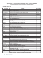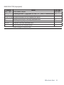
1
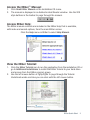
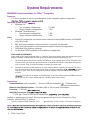
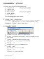
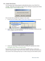
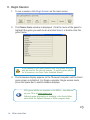
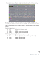
EEGer™ Quick Start Guide
Table of Contents
Introduction
1
Accessing the EEGer Manual & EEGer Tutorial
2
Access the EEGer Manual
3
Access EEGer Help
3
View the EEGer Tutorial
3
System Requirements
4
BASIC OPERATION
5
STARTING YOUR HARDWARE AND SOFTWARE
5
RUNNING EEGer SESSIONS
6
™
I.
Create Client - Clinical Use Only
6
II. Select Client
8
III. Choose Layout - Clinical Use Only
9
IV. Plan Session - Clinical Use Only
10
V. Begin Session
14
VI. Run Session
18
VII. Post-Session and Other Options
19
a. Replay Raw Data
19
b. Review
19
c. Spectral
20
d. Client File Management
20
Appendix A — Keypresses Commonly Used During Feedback
22
Appendix B — What Is This?
24
Version 4.2 REV122611
Introduction
Welcome! We’d like to thank you for purchasing EEGer™ and hope that you
enjoy
the new software. There are a number of exciting new features available.
This manual is designed to give you a brief overview of the basic requirements
and functionality of EEGer™ to get you started quickly.
•
• Instructions for accessing the Tutorial and complete EEGer Manual
• System Requirements
• Basic Operations
Keystrokes Most Commonly Used During Feedback
For more in-depth information, please refer to the EEGer Manual available on
your installation CD or on the web at http://www.eeger.com.
The EEGER website is also a great source of other useful
information. You can also download the very latest updates for your EEGer™
program and related software.
Please visit us at www.eeger.com.
EEGer Quick Start 1
DOS & WINDOWS® 98 UPGRADE USERS: Your system must be running Windows XP
or later to perform the installation or take advantage of the documentation available
on the CD. DOS and Windows 98 systems are not able to run EEGer software
version 4.2 or later. Please review the system requirements carefully to be sure the
Client/Game system is compatible with EEGer.
To run Windows on the Client/Game computer, press Esc to exit the game menu.
Accessing the EEGer™ Manual & EEGer Tutorial
Insert your EEGer Installation CD and the installation menu appears.
(If it does not, double-click the CD/DVD drive in “My Computer”.)
2 EEGer Quick Start
Access the EEGer™ Manual:
1. Click Read EEGer Manual on the Installation CD menu.
2. The manual is displayed in an Adobe Acrobat Reader window. Use the VCR
style buttons in the toolbar to page through the manual.
Access EEGer Help:
The EEGer manual contents are included in the EEGer Help that is available,
with index and search options, from the main EEGer screen.
Click the Help menu in EEGer to select Help Manual.
View the EEGer Tutorial:
1. Click the EEGer Tutorial icon to run the application from the installation CD or
go to Additional Installations to install the EEGer Tutorial to your hard drive
and access from the EEGer program group.
2. Use the left mouse button or PgUp/PgDn to page through the Tutorial.
Underlined words are links you can click with the left mouse button.
EEGer Quick Start 3
System Requirements
MINIMUM Recommendations for EEGer™ Computers
Processor
1.8 GHz or greater; do not mix manufacturers in two-computer system configuration
Operating System & RAM
• Windows® XP
> Two computer configuration:
512 MB
> Single computer configuration:
1 GB
• Windows® Vista/Windows 7
> Two computer configuration:
2 GB
> Single computer configuration:
3 GB
Video
• DirectX 9.0 supported, accelerated video card with at least 64MB memory for 800x600
with 16-bit color
• Mid-level game graphics recommended for 2-computer configuration
• High-level game graphics recommended for single-computer configurations.
• Dedicated video memory preferred.
• Do not select INTEL graphics for Dual Monitor configuration.
VIDEO CARD REQUIREMENTS
Video cards are the most significant factor in ”usability” since they directly affect the therapist and game
display. Feedback is independent of video speed, but responsiveness to keystrokes is not.
1.
You must be able to use DirectX version 9.0. However, if you upgrade your version of DirectX to the
current version, you must first be sure that your card has drivers that are compatible with that version of DirectX. If not, it will be necessary to replace your video card.
2.
Displays are affected by the amount of on-card memory and the resolution you choose. You must
or higher
have at least 64mb of on-card memory, but if you use larger resolutions
color sets, you’ll need more memory. Most currently available cards provide at least 256 MB of
memory.
The minimum resolution of 800x600 with 16-bit color setting requires 64 MB of memory.
An increase to 32-bit color setting requires 128 MB of video card memory.
Connections
Communications (each computer) - 1 Serial or USB-serial adapted
1 Ethernet port
(Ethernet recommended)
Video for Dual Monitor system - Secondary VGA or DVI port with VGA adapter.
Licensing - 1 USB slot
Amplifier Connection
1 USB
1 Serial or USB-serial adapted port
Laptops or desktops may be used. Most newer laptops will work for the Therapist or Client
computer with the EEGer™ software.
Technical Support: EEGER Affiliates - Free
4 EEGer Quick Start
Non-Affiliates - $100 per hour (15 minute increments)
BASIC OPERATION
This booklet is designed to give you a quick overview of EEGer™ to get you
started. Refer to the EEGer manual on the installation CD for more details
on the software features and options.
STARTING YOUR HARDWARE AND SOFTWARE
Once the software and hardware are installed, we recommend that you
connect/disconnect cables and other devices used with your computer(s) with
the power off. If you must connect anything with the power on, attach only
one thing at a time to allow Windows to configure them properly.
1. Turn on your computer(s).
2. If necessary, disable any hardware or software and make adjustments
that are necessary to avoid interference during a live neurofeedback
session
.
3. Start the Software:
Double-click the EGS icon on the Game/Client computer first if
you use a two-computer configuration. Check the communication
selection in the upper-left corner to be sure the correct choice is
displayed.
Double-click the EEGer icon on the Therapist computer.
•
If a message regarding port settings is displayed, it is meant to notify you
that a your EEGer setup choices do not match the available communication
options. Note which ports are not valid and which are available.
•
The
message
appears if the communication options are not set correctly or if the Game/
Client computer does not have the EGS Game menu displayed. In the latter
case, double-click the EGS icon then click Retry. For incorrect connections,
review the installation guide for correct settings.
EEGer Quick Start 5
RUNNING EEGer™ SESSIONS
The basic steps involved in running EEGer are:
I. Create Client
(Clinical Systems Only)
II. Select Client
III. Choose Layout
IV. Plan Session
(Clinical Systems Only)
V. Begin Session
VI. Run Session
VII. Post-Session and Other Options
I. Create Client - Clinical Use Only
Clinical Use:
Client creation and setup can only be performed using EEGer
Clinical Systems. You must complete the first two steps.
Remote Use: Proceed to Item II - Select Client.
IA. Create New Client ID
1. From the Client menu, select Create New Client ID.
2.
3. Enter an ID for the client, using up to 31 characters without spaces or
punctuation.
4.
Click OK to save and continue to the next screen.
5.
Enter the client’s name, using up to 64 characters.
6.
Click OK to save.
7.
Enter the client’s date of birth (MM/DD/YYYY).
8.
Click OK to save.
Enter the client’s biological sex (N/F)
Click OK to save.
Proceed to IB - Create Client Class.
6 EEGer Quick Start
IB. Create Client Class
The Choosing Class dialog appears automatically when a new Client ID is
created. Select the class type for this client by clicking the appropriate button:
BetaSMR, Alpha-Theta or Experimental.
You can also set up additional classes for the client:
1. From the Client menu, select Create Client Class (formerly Create Client Protocol).
2. Select the Client ID you created from the list of available clients and click
OK (or double-click the Client ID).
3. Select the class type for this client by clicking the appropriate button:
BetaSMR, Alpha-Theta or Experimental.
Experimental class allows you to try alternative BetaSMR settings, including the
optional screening layouts. Note that the data, histories, and reports are separate for
each protocol class (although they may be combined using the Archive/Move option).
EEGer Quick Start
IC. Create Remote Use Disk (Optional)
Please refer to the separate Therapist/Client instructions supplied with
purchase of a Remote Use system.
Additional information is available in the complete EEGer™ Manual (available on
the installation CD or at www.eeger.com) The EEGer Tutorial outlines step by step
directions for setting up Remote Use Session Plans. (Refer to page 2-3 of this
booklet for access instructions.)
II. Select Client
1. Insert Remote Use Storage Device (Flash drive), if used.
2. Click Select Client on the main EEGer screen.
3. Choose the appropriate Class/Client ID from the list of available clients
and click OK (or double-click to select).
REMOTE SYSTEMS: Click the drive letter that contains your Remote
Use Session Plan (click the BIG button on the screen) and the client from
the external disk drive is automatically displayed.
4. At this point the client’s name is displayed on the main screen and the
other buttons become active.
5. REMOTE SYSTEMS: Proceed to Step V - Begin Session.
8 EEGer Quick Start
III. Choose Layout - Clinical Use Only
1. Click Choose Layout.
2. Click the corresponding layout button to choose the traces for
the EEG training display:
BetaSMR layouts:
•
5-trace -- ChA, ChB, Inhibit, Reward, Inhibit (EEGer 4.0 display)
•
6-trace inhibit -- ChA, ChB, Inhibit, Inhibit, Reward, Inhibit
•
6-trace reward -- ChA, ChB, Inhibit, Reward, Reward, Inhibit
•
8-trace (DUAL MODE) -- ChA, ChB, Inhibit, Reward, Inhibit, Inhibit,
Reward, Inhibit
•
Reward-only -- ChA, ChB, Monitor, Reward, Monitor
Alpha-Theta layouts:
•
5-trace -- ChA, ChB, Inhibit, Reward, Inhibit
•
6-trace inhibit -- ChA, ChB, Inhibit, Inhibit, Reward, Inhibit
•
8-trace (DUAL MODE) -- ChA, ChB, Inhibit, Reward, Inhibit, Inhibit,
Reward, Inhibit
Experimental layouts:
•
All BetaSMR Layouts
•
Optional Screening Layouts
»
ChanA, screen - 12 Monitor traces for ChA; multiple default
Setup stages
»
2-chan, screen - 6 Monitor traces for ChA, 6 Monitor traces for
ChB, multiple default Setup stages
»
ChanB, screen - 12 Monitor traces for ChB; multiple default
Setup stages
EEGer Quick Start 9
IV. Plan Session - Clinical Use Only
1. Click the Plan Session button to display the EEGer™ Stage Edit screen
and specific session information.
Note: The session planning screen default settings are dependent on the
option selected in Choose Layout.
Each client requires a “session plan”. This is where initial site locations,
frequencies, feedback modes, and autogoal selections are made. Most
selections are changeable during a session but an initial plan is required. A
session plan is comprised of “stages”. There are two kinds of “stages”: Setup
stages (electrode placement, frequency/mode establishment) and Run stages
(specified time). Each client has a session plan for each protocol.
This display has three “panes”:
• The leftmost pane is where stages are created or selected. At the top of
the left pane is a series of buttons showing which “stage” of a session is
being modified. Clicking these buttons “selects” that stage for modification. The bottom of the left pane has buttons for creating and deleting
stages or changing the stage type.
‚ In the center pane are the values for the currently selected stage.
ƒ On the right pane for Setup stages is a symbolic head with electrode
placements and a graph showing the frequency bands for the current filter
frequency settings.
10 EEGer Quick Start
2. Create Session Plan
a. Specify Setup Stage Settings
Site locations: Click in one of the Input channels. You can then type in values
or click Clear to erase the current settings and use the mouse to click on desired
locations on the Head Map displayed at right.
10-20 or 10-10 layout: When editing an Input Channel, you can switch the
locations displayed on the Head Map between 10-20 and 10-10 options (more
advanced sites) by clicking the button on the right side above the Head Map.
Inhibit(s): Click in the lower or upper range field to change the frequency, or use
the Up and Down arrow buttons to increase or decrease the value.
Reward(s): Click in the fields to change the low or high end of the frequency, or
use the Up or Down arrow buttons to increase or decrease the value by a whole
number. Click the Reward button to change Reward Mode.
Monitor(s): Click in the lower or upper range field to change the frequency, or
use the Up and Down arrow buttons to increase or decrease the value. These
traces are not included in determining rewards.
Pause at end of setup: Check this box to allow time between stages. Uncheck
the box to move to the next stage without interruption.
Feedback Mode: Click the Feedback Mode button (top center) to display choices
for initial feedback modes. At actual feedback time, any unlicensed condition will
cause SingleA (single channel, A input) to be selected. Of course, you can change
the feedback mode (using F3) during the actual feedback process.
The feedback modes work as follows:
SingleA - Single channel, source data from the “A” input channel
SingleB - Single channel, source data from the “B” input channel
Sum - Sum of A & B channels is used as source data
Differ - Difference of A & B channels is used as source data
Psync - Compares filtered A & B envelopes (Synchrony)
Async - Compares filtered A & B envelope slopes (Comodulation)
GAsync - Compares lowpass A & B envelope slopes (Global Comodulation)
AminusB - Difference between filtered A & B envelopes
BminusA - Difference between filtered B & A envelopes
PDelta - Phase difference between A & B signals
RatioA - Input is A; reward is ratio of reward trace to inhibit trace just above reward trace
RatioB - Input is B; reward is ratio of reward trace to inhibit trace just above reward trace
Dual - Input is A & B lowpass values (A feeds 3 traces, B feeds 3 traces); reward is SMR
MonitorA - Input A lowpass value; No rewards or game outputs
MonitorAB - Input A & B lowpass values; 6 traces from A, and 6 from B; No rewards/game outputs
MonitorB - Input is B lowpass value; No rewards or game outputs
Additional choices are available if the ANI ZScore module is installed. Refer to the ZScore
appendix in the EEGer™ Manual or program Help.
EEGer Quick Start 11
Autogoal Settings: Click Autogoal settings at the bottom of the
session planning
screen to bring up a menu that allows adjustment of threshold
values used when F11 is pressed (BetaSMR example).
• Any stream with 0% selected has NO change with F11.
• The Minimum µv value is the minimum (measured average
value) threshold is “automatically” set by F11.
• The Maximum µv value is the largest threshold value set by F11.
• The frequency of Autogoal adjustment is set using a toggle
button. Click the button to select:
» Autogoal only on F11
» Automatic autogoal every rest period (seconds must be 0)
» Enter a number of seconds to select Autogoal every #
seconds
Click OK to save settings and return to the setup stage planning
b. Specify Run Stage Settings
Clicking a Run button brings up a slightly different screen.
Notice there is no “head” shown. The important field on this screen
is Minutes to run. Enter the number of minutes you want to run the
settings displayed in the preceding Setup stage.
To run a session manually, you can delete the Run stages from
setup. You can also check Pause at end of run to have the program
wait for your instruction so that you can prepare for the next phase.
12 EEGer Quick Start
c. Other Setup Options
• Preset Settings
Clicking the Presets button (top center) brings up a selection
list of defined settings. These are the values available from the
user-defined presets established using the Preferences menu
(Edit filter setups). Use them to automatically fill in settings you
commonly use for your clients’ sessions.
•
Inserting and Deleting Stages
»
»
»
Clicking Insert Before or Insert After button adds a
new stage with a type of “Empty”.
An Empty stage type must be assigned a type by
clicking Run or Setup.
The Delete Current button deletes the stage.
3. Click OK to save all of your session plan specifications.
ð
EEGer Quick Start 13
V. Begin Session
1. To run a session, click Begin Session on the main screen.
2. The Choose Game window is displayed. Click the name of the game to
highlight the game you wish to run and click Select, or double-click the
game name.
If you choose to Edit game options from this screen, they will
only be used for the current session. To modify game options
for all sessions, use Tools-Tailor Installed Games.
3. The brainwave display appears on the Therapist computer and the Client
game screen is initialized. For Single-computer, Single-screen mode,
press the Space Bar to switch between displays.
EGS game details are available in the EEGer™ User Manual
on your CD or at www.eeger.com.
Optional game information is available in the Quick Reference Guide for Optional Games or EEGer program Help.
ð
14 EEGer Quick Start
This sample shows a typical single channel setup for the 5-trace display.
The top two streams are the input channels (labeled “A” and “B”). In this
example, the “A” channel electrodes are at C4-A2. The three streams below
that are reward and inhibit streams (labeled at about the middle of each stream
display).
Possible legends are:
a.
b.
c.
d.
ArtI
Inhb
Rwrd
Down
Artifact Inhibit (lowpass data)
Inhibit
Reward (signal above threshold)
Reward (signal below threshold)
Additionally, for advanced users:
e.
f.
g.
h.
Cntr
Elev
DevU
DevD
Reward (signal close to threshold)
Reward (signal above threshold, clamp to threshold)
Reward (deviation above)
Reward (deviation down)
ð
EEGer Quick Start 15
The current frequency range of each stream is shown at the left next
to the color blocks that contain the trace number. The “color” of the
blocks is based on the center frequency of the frequency range (using
the customizable colors selectable from the Tools menu). Other trace
information includes:
•
•
•
•
•
•
•
•
•
Scale, Thresh, and Avg values are microvolts (peak-to-peak).
The %above value is the percent of time the signal was over the threshold
voltage (smoothed over the previous 30 seconds).
The Avg value is the average value of the signal smoothed over the previous 30
seconds.
The blue horizontal lines represent the relative position of the threshold setting.
The (frequency) colored bars at the bottom are a measure of the energy
contained in each 1 Hertz frequency range from 0 to 45 Hz. They are computed
as FFT (Fast Fourier Transform) values every ½ second.
The Raw stream shows a horizontal GREEN line when all reward criteria are
met (no artifact/inhibit & all rewards OK). The vertical GREEN line indicates
when a reward (beep) is issued.
The reward stream shows a GREEN line in the center when the signal is over
threshold.
The inhibit band displays a RED line when the signal is above threshold.
GREEN lines must be present in the Reward band to issue a reward, but if RED
lines appear in the Inhibit band no reward is issued.
The bottom area of the screen has a number of regions of data. Shown
below are some boxes with text inside. This is a graphical representation of
the session plan.
•
•
•
•
•
The little boxes with “S” inside represent Setup stages.
The run stages have the setup text from the previous setup and a width
proportional to the specified run time.
The entire bottom width is scaled to represent the maximum session time (from
the preferences screens).
The white bar is filled in to show the current position in the session plan.
The boxes, text, and bar disappear if the session plan is no longer being
followed (e.g., if no Run stage is present or Ctrl+F5 is used for manual run).
ð
16 EEGer Quick Start
Below the stage information boxes is a line of status information.
•
•
•
•
•
•
The leftmost field contains the current status of feedback (Pause, Run, Rest,
Stage) with a different background color for each status.
» Pause indicates an operator action (F5) is required to continue the session.
» Rest is shown during the rest periods between game periods and implies no
operator action is required.
» Stage displays when there is an operator action/decision needed (move
electrodes, continue/change session process, etc.).
The current period, score, and feedback time (minutes:seconds) is shown to the
right of the current status. Next is shown the current feedback mode (SingleA).
There are a number of flags and operator-changeable modes whose state is
shown in the middle of this line.
Possibilities are:
+PB
playback mode (not live)
+Gen
signal generator mode
+Athr
autothreshold (auto F11) at beginning of rest period
+Astg
auto stage processing enabled
-DC
DC compensation turned off
-Ainh
artifact inhibit turned off
-lpf
lowpass filter disabled
-Nuse
unused raw trace data is suppressed
Eopn
eyes open
Ecls
eyes closed
Further right, the current time of day (24hr clock) is shown.
At the lower-right edge, the battery-operated amplifier voltage is shown (or NONE
if no amplifier is being sensed). If another I/O device is used, other data may
show here. In all cases, a flashing RED message indicates a fatal error condition.
The bottom two lines contain program messages, in this case displaying the
setup-specified site locations.
EEGer Quick Start 1
VI.
Run Session
During a session there are certain actions that can be taken to adjust
the display and client feedback. Press F1 for Help to display a list of
available options and keypresses. The most common keypresses are
listed in Appendix C of this guide.
Run/Pause (F5)
When the brainwave screen first appears, it is in Pause mode. When the
Client’s game screen is ready:
•
•
•
Press F9 to autoscale the traces
Press F11 to initialize Autogoal
Press F5 to change to Run mode and begin the session. To Pause
the session, press F5 again.
Single Computer (Space)
Press the Space Bar to choose between training and game display.
Adjust Scale (F9)
Sometimes the display of waves would be easier to read if they were displayed
larger or smaller. Scale is used to zoom in or out on the wave display. Press
Page Down (PgDn) or Page Up (PgUp) to select the line you wish to adjust.
Press F9 to activate scale adjustment. Use the plus (+) and minus (–) keys to
increase and decrease the scale. The larger the scale, the smaller the display.
Press Enter twice to leave the trace.
Adjust Threshold (F11)
Depending on the current mind-state of the client, it might be advantageous to
modify the thresholds to adjust the reward or inhibit feedback. Pressing F11
if a stream is selected, will choose appropriate threshold value for only that
stream. If the stream is a lowpass stream, the threshold adjusts based on 1%
over threshold as target. If no streams are selected, EEGer will choose appropriate threshold value for all non-lowpass streams. If the user-specified threshold percentage is zero, no autothreshold action is ever taken on that stream.
Changing Stages (Auto-stage or F4)
When the session plan is set for a second stage, the program can automatically
pause before the second protocol setting begins to run. Press F5 to continue
the training when ready to run the second stage. You may also manually switch
by pressing F4 to change to the next stage. This change also turns off the
Autotimer. To restart the Autotimer for the next stage, press Ctrl-F4.
ð
18 EEGer Quick Start
Notes (F8 or Shift+F8)
Pressing F8 opens a full-screen text Editor for note taking. Shift+F8 causes the two
bottom lines to be used as a single-line text entry area for notes or “marks”.
Help (F1)
Press F1 at any time to display a Help screen of keys and their associated function.
Exiting the Brainwave Display (Esc)
When the session is complete, press Esc to exit the brainwave display.
VII. Post-Session and Other Options
1. Replay Stored Data
After running a client session, the data can be displayed and analyzed using
the Replay Stored Data selection from the main screen. Note: This feature
replays the data, but not the settings used during the session. It is not like
replaying a tape of the session.
2. Review
You can compare the data from multiple sessions with the Review option from
the main menu. The following image is an example of the line graph display.
Refer to the EEGer Manual or program Help for more details.
When Review is first opened, the graph for last session run appear in the
upper section. The Trend graph appears in the lower section. Click the datelabeled area of the Trend graph to view a different session graph at the top.
Move the cursor over the upper graph to view session details at the top of the
display for any given point in the session.
You can also print the Summary, Detail or Trend graph directly to your
Windows default printer or to a file for printing later or sending for a
consultation. (NOTE: EEGer prints to a printer by default. To change that option, go to
Preferences-Configuration and select the Setup tab. Click to uncheck “Print directly to
default printer” and save.)
Refer to the EEGer™ Manual or program Help for more information.
EEGer Quick Start 19
3. Spectral
F1 - Help, List of all control keys
Pause - Pause or Resume playback
C - Continue/Start
P - Pause
Esc - Quit
F6 - Save screen shot
F12 - Toggle number of channels
4. Client File Management
a. Archive Client
From the Files menu, select Archive and click the Archive button. You are
prompted to select the client and files to be archived. The Archive function
reduces the size of the files and saves them in a separate directory. The
archived sessions do not appear for Review/Spectral/Replay. Use the Unarchive
button to restore the historical sessions.
b. Edit Client Name or Birthdate
To edit a client’s full name or birthdate, click the Client menu and select Edit
Client data. Select the client ID you wish to update. Enter any changes to the
client name and click OK, then edit the birthdate (MM/DD/YYYY) and click OK.
The correct birthdate is necessary for ANI ZScore modes.
c. Rename an Existing Client
To change the Client ID, click the Files menu and select Archive. Click the button
labeled Rename an existing client. Select the client to rename, then enter a
new Client ID and click OK.
d. Delete Individual Client Files
From the Files menu, select Archive. Click either Delete files from active client
or Delete files from archived client. Select a Client ID and choose files to delete.
e. Delete Client
From the Files menu, select Archive and click button labeled Permanently delete
an entire client without possible recovery. You are prompted to select the client
and confirm deletion. This process removes all data for the selected Client ID.
f.
Move Session Data to a Different Client ID
From the Files menu, select Archive. Click the button labeled Move files from
active client/class to another client. Select the ID that includes the files you
want to move. Choose the files to be moved. Select the destination client ID.
The session data is transferred to the Client ID folder for the chosen client.
20 EEGer Quick Start
g. Back Up Client Files
It is important to back up your client files to another computer or external drive
in case of hard drive failure. How you do this depends on
your hardware environment. You can burn the files to CD, store on an external
device such as a ZIP drive or USB memory stick, back up to another hard drive,
or use any other procedure that works for you.
1.
Manual file backup
FILE STRUCTURE:
C:\(Hard Drive Root Directory)
\EEGer
\CLIENTS
\YourClientID
\SMR
\AT
2.
WHICH FILES SHOULD I BACK UP?
Back up the files in the EEGer\CLIENTS folder. You can do the entire folder or back
up each ClientID folder individually. The “eegdemo” and “ET_data” sample clients
can always be recovered by reinstalling EEGer.
Also, back up the C:\EEGer\Preferences folder. Your license file and game options
are stored in the Keys subfolder. If you have archived clients (to make them
inactive), you should also back up the C:\EEGer\Archive folder.
NOTE: if you have changed the default folders for EEGer, you should back up
wherever you have redirected those folders!
HOW DO I RESTORE FILES?
How you restore files depends on how you backed up the files. Copy the files
you’ve backed up into the appropriate folder through My Computer in Windows. If
you used a compression utility for backup, such as WinZip, you’ll need to extract
the files to copy them into the appropriate location.
If you stored the entire CLIENTS folder, you can copy the entire CLIENTS folder
into the EEGer folder, replacing the contents.
You can copy the individual ClientID folders into the EEGer\CLIENTS folder.
a.
Individual sessions can be copied into the appropriate protocol folder for the
client. View the file’s date/time property to determine which file corresponds
to the session.
b.
When
finished copying files, open EEGer. Go to the Clients menu and select Rebuild
c.
Client Index File.
NOTE: If you are prompted to replace a file, only do so if the file to be replaced is
OLDER than the file you are copying to the drive.
EEGer Quick Start 21
Appendix A — Keypresses Commonly Used During Feedback
(complete list available on Help screen and in the EEGer Manual)
NO BAND SELECTED
Function
Action
Select band to adjust
F1
Help (F1 again to exit)
F2 / Shift+F2
Cycle for Downtraining or other reward mode
F3 / Shift+F3
Switch Channel (A to B); cycle or popup feedback mode menu
Ctrl+F3
Toggle game color
Alt+F3
Toggle Low Pass filter
F4
Switch protocols (next Stage)
Shift+F4
Turn Autostage back on
Ctrl+F4
Change to previous session frequency
F5
Start/Stop
Ctrl+F5
Turn off automatic timer – Manual run
F6
Save current EEG display to print
Ctrl-F6
Change feedback source
Alt+F6
Sine wave signal generator
F7
Toggle integral display (debug)
Ctrl+F7
Impedance for J&J amplifiers (Ctrl+F7 to return)
F8
Insert comment (text)
Alt+F8
Toggle Arti Inhib
F9
AutoScale training bands (no band selected)
Ctrl+F9
Single scale A-adjust
F10 / Shift+F10 Increase/Decrease spectral display band height
Ctrl+F10
Hide spectral bands
Alt+F10
FFT markers On/Off
F11
AutoThreshold all traces (no band selected)
Ctrl+F11
Toggle AutoThreshold at stage and AutoThreshold with F11
F12 / Shift+F12 Graph of live session trend and spectral mirror (F12 to return)
Ctrl+F12
Toggle draw speed
Alt+F12
Toggle “hide unused traces”
Ctrl+é or ê Increase/Decrease REWARD frequency
Alt-A / Alt-B
Insert text note if protocol changed
Esc
End session and exit
Space
Toggle single-computer Therapist/Game display
% or G / V / T / O Adjust Goal, Volume, or Tactile settings
D/F
Adjust Therapist Display or Feedback Display options
PgUp / PgDn
22 EEGer Quick Start
DOS Key
PgUp/PgDn
F1
Ctrl+F2
F3
automatic
F4
F5
F6
F2
F11
Esc
BAND SELECTED (Highlighted)
Function
PgUp / PgDn
Action
Select band to adjust
DOS Key
PgUp/PgDn
+/–
Increase/Decrease: 1. scale value (F9, then + or -, Enter) 2. threshold width + / Ctrl+ç or è Increase/Decrease LOWER frequency for band
Ctrl+é or ê Increase/Decrease UPPER frequency for band
F9
Manually set scale for currently selected band
Alt-E
Alternately change Eyes open/closed state
Ctrl+F9
AutoScale currently selected band
AutoThreshold for selected band
Finish change on current band
F11
Enter
F2
Enter
EEGer Quick Start 23
Appendix B — What Is This?
These images provides a visual aid for items distributed with neurofeedback component kits. The
items you receive are dependent upon your computer configuration and amplifier model. Not all
items listed here are included in your shipment.
SOFTWARE INSTALLATION DISKS
1.
2.
3.
4.
5.
6.
EEGer™ Installation CD
EEGer Keyblock File CD
SpaceRace Installation CD
Chomper Installation CD
BoatRace Installation CD
BeyondVR Cybernetic Interface System 2-CD Installation Set (for StarLight, Squared,
INtoIT, Kaleidoscape, and StoneSoup installation)
SECURITY KEYS
1.
2.
3.
4.
EEGer dongle
DOS NeuroCog dongle (obsolete)
BeyondVR USB HASP key (black or green key)
BeyondVR Parallel HASP key (obsolete)
CONNECTION CABLES AND DEVICES
1.
2.
3.
4.
Null Modem Cable
Ethernet Cable (crossover or direct)
USB-Serial adapter with driver installation CD
USB 4-port Hub with power supply
24 EEGer Quick Start
AMPLIFIER & COMPONENTS esiPRO 4.3
1.
2.
3.
esiPRO 4.3 amplifier
USB cable
esiPro 2.2 amplifier
J&J Technologies
1.
2.
3.
4.
5.
BrainLynx amplifier
GP+ amplifier (obsolete)
C2-Mini amplifier with XP1.0 USB adapter (obsolete)
TP-60 Electrode adapter (C2-Mini and GP+)
Shorting plug (C2-Mini and GP+)
Thought Technology
1.
2.
3.
4.
5.
6.
7.
ProComp Infiniti 8-channel amplifier
ProComp2 2-channel amplifier
Fiber optic cable
ProSB interface adapter
9-25 Pin Null Modem Cable
FlexPro pre-amplifier (ProComp 8-channel and ProComp2 ChB only)
DIN electrode adapter
EEGer Quick Start 25