1
P1000 Installation Guide
P1000
Installation Guide
Ver. Draft 1.2_2009/06/29
P1000 Installation Guide
System box module installation caution note
CAUTION: Before installing or removing the CPU Box into the system unit, please make
sure that the system power is turned off and the AC power adaptor is disconnected from
the system unit.
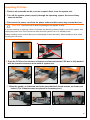
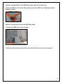
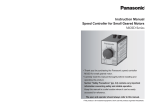
Correct installation PC Box Procedure:
①. Push the CPU Box into the base of system, and ensure that the CPU BOX is fully
docked with the internal connector at the back of system unit.
②. Raise the handle, as indicated, and make sure that the 2 thumb screws, as shown,
are locked..(The 2 thumb screws place in Accessory box.)
P1000 Installation Guide
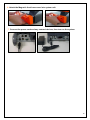
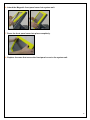
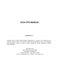
③. Attach the Magnetic front base cover into system unit.
④. Connect the AC power adaptor to the system as shown.
⑤.Turn on the power.
P1000 Installation Guide
Federal Communications Commission (FCC)
This equipment has been tested and found to comply with the limits for a Class A digital device, pursuant
to Part 15 of the FCC Rules. These limits are designed to provide reasonable protection against harmful
interference in a residential installation. This equipment generates, uses, and can radiate radio frequency
energy and, if not installed and used in accordance with the instructions, may cause harmful interference
to radio communications. However, there is no guarantee that interference will not occur in a particular
installation. If this equipment does cause harmful interference to radio or television reception, which can
be determined by turning the equipment off and on, the user is encouraged to try to correct the
interference by one or more of the following measures:
Reorient or relocate the receiving antenna.
Increase the separation between the equipment and the receiver.
Connect the equipment to an outlet on a circuit different from that to which the receiver is connected.
Consult the dealer or an experienced radio/TV technician for help.
Shielded interconnect cables and shielded AC power cables must be employed with this equipment to
insure compliance with the pertinent RF emission limits governing this device. Changes or modifications
not expressly approved by the system’s manufacturer could void the user’s authority to operate the
equipment.
Declaration of Conformity
This device complies with part 15 of the FCC Rules. Operation is subject to the following two conditions:
1. This device may not cause harmful interference
2. this device must accept any interference received, including interference that may cause
undesired operation.
DHHS- the CD-ROM Drive
FDA Regulations require the following statement for all laser-based devices:
“Caution, Use of controls or adjustments or performance of procedures other than those specified herein
may result in hazardous radiation exposure.”
CAUTION: This appliance contains a laser system and is classified as a “CLASS 1 LASER
PRODUCT”. To use this model properly, read the instruction manual carefully and keep this manual for
future reference. In case of any trouble with this model, please contact your nearest “Authorized Service
Station”. To prevent direct exposure to the laser beam, do not try to open this enclosure.
P1000 Installation Guide
Important Safety Information
SAFETY INSTRUCTIONS
1. Please read these safety instructions carefully.
2. Keep this User’s Manual for later reference.
3. Disconnect this equipment from the AC outlet before cleaning. Don’t use liquid or spray detergent for
cleaning. Use only a moistened sheet or cloth.
4. For pluggable equipment, the socket-outlet should be installed near the equipment and should be
easily accessible.
5. Keep this equipment from humidity.
6. Lay this equipment on a stable surface when installing.
7. Do not leave this equipment in an non-air-conditioned environment, or in a storage temperature above
60∘C. Such conditions may damage the equipment.
8. The openings on the enclosure are for air convection and protect the equipment from overheating. DO
NOT COVER THE OPENINGS.
9. Check the voltage of the power source when connecting the equipment to the power outlet.
10. Place the power cord so that it will not be stepped on. Do not place anything over the power cord.
The power cord must be rated for the product and for the voltage and current marked on the product’s
electrical ratings label. The voltage and current rating of the cord should be greater than the voltage
and current rating marked on the product.
11. All cautions and warnings on the equipment should be noted.
12. If the equipment is not used for a long time, disconnect the equipment from the mains to avoid
damage.
13. Never allow liquid into ventilation openings. This could cause fire or electrical shock.
14. Never open the equipment. For safety reasons, qualified service personnel should only open the
equipment.
15. If one of the following situations arises, get the equipment checked by service personnel:
a. The Power cord or plug is damaged.
b. Liquid has penetrated the equipment.
c. The equipment has been exposed to moisture.
d. The equipment does not work well or you cannot get it work according to the user’s manual.
e. The Equipment has been dropped and damaged.
f. The equipment has obvious signs of damage.
WARNING! Not intended for Outdoor Use.
CAUTION: Danger of explosion if battery is incorrectly replaced. Replace only with same type,
and discard used batteries according to manufacturers instructions.
P1000 Installation Guide
Copyright
The information in this guide is subject to change without prior notice.
The manufacturer shall not be liable for technical or editorial errors or omissions contained herein, nor
for incidental or consequential damages resulting from the furnishing, performance, or use of this
material.
This manual contains information protected by copyright. No part of this manual may be photocopied or
reproduced in any form without prior written consent from the manufacturer.
© 2009 All rights reserved.
The software described in this guide is furnished under a license agreement or nondisclosure agreement.
The software may be used or copied only in accordance with the terms of the agreement.
Product names mentioned herein may be trademarks and/or registered trademarks of their respective
companies.
First Edition April 2009
P1000 Installation Guide
Table of Content
Chapter 1
Introduction...............................................................................................................1
P1000 Characteristics ...........................................................................................................1
How to Use This Manual .......................................................................................................2
Specifications ........................................................................................................................3
A Visual Tour of P1000..........................................................................................................4
Front View.................................................................................................................................4
Rear View..................................................................................................................................5
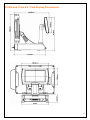
Dimensions ............................................................................................................................8
P1000 Dimensions ...................................................................................................................8
P1000 and MSR Dimensions ...................................................................................................8
P1000 and 15cm 8.9” Pole Display Dimensions....................................................................9
P1000 and 15cm VFD Pole Display Dimensions ................................................................. 10
Connector Panels ................................................................................................................ 11
Primary Connector Panel ...................................................................................................... 11
Second Connector Panel....................................................................................................... 12
Chapter 2
Hardware Setup ...................................................................................................... 13
P1000 Assembly .................................................................................................................. 13
Warnings and Cautions ......................................................................................................... 13
Installing CPU box ................................................................................................................. 14
Changing Front Panel Cover................................................................................................. 16
Changing Front Base Cover.................................................................................................. 18
Removing the CPU box and box cover ................................................................................ 19
Replacing the CPU box cover ............................................................................................... 20
Installing UPS......................................................................................................................... 21
Installing Additional Memory Card ....................................................................................... 23
Populating DIMM Sockets .................................................................................................. 23
Installing DIMMs.................................................................................................................. 23
Removing and Replacing the SATA Hard Disk ................................................................... 25
Installing Compact Flash Card ............................................................................................. 27
Installing MSR/Fingerprint/I-Button module ........................................................................ 28
Installing 8.9” pole display and VFD pole display............................................................... 29
P1000 and 8.9” 15cm pole display full view...................................................................... 31
P1000 and VFD 15cm pole display full view ..................................................................... 31
Installing Cash Drawer .......................................................................................................... 32
Main Board Configuration................................................................................................... 33
Main Board Pin Definition ..................................................................................................... 33
Clearing CMOS....................................................................................................................... 35
I/O Board Configuration ...................................................................................................... 36
IOTR Board Pin Definition ..................................................................................................... 36
Top IO Board Pin Definition .................................................................................................. 43
Bottom IO Board Pin Definition ............................................................................................ 45
P1000 Installation Guide
Chapter 3
Software Setup ....................................................................................................... 48
Driver Software List............................................................................................................. 48
Intel Chipset Driver Installation.......................................................................................... 49
Intel Graphics Driver Installation ....................................................................................... 50
ELO Touch Screen Driver Installation ............................................................................... 51
Audio Driver Installation ..................................................................................................... 53
Gigabit LAN Driver Installation........................................................................................... 54
Wireless LAN Driver Installation (optional) ....................................................................... 55
RFID Driver Installation (optional)...................................................................................... 56
Fingerprint Reader Driver Installation (optional) .............................................................. 57
System Driver Installation (Required for Cash Drawer and UPS) ................................................. 58
OPOS Driver Installation........................................................................................................... 59
MSR Driver Installation (optional) ...................................................................................... 60
Appendix A. Sample C++ Cash Drawer Code for Windows ..................................................... 61
Appendix B. Sample Visual Basic Cash Drawer Code for Windows ....................................... 62
Chapter 1
Introduction
P1000 Characteristics
¾
P1000 uses a high speed processor capable of handling a high capacity data efficiently.
¾
P1000 solid quality Magnesium-Aluminum & Aluminum Die-casting housing distinguishes it
from ordinary plastic housings.
¾
The P1000 touch terminal all-in-one design combines a powerful PC, multiple LCD and touch
screens, which are suitable for any market. The primary LCD panel can be tilted at multiple
angles.
¾
P1000 functionality extends far beyond the standard setup. P1000 can be adapted for a
variety of uses with the addition of any of the following options: Magnetic Stripe Card Reader,
Fingerprint Reader, I-Button Reader, RFID, WIFI/Bluetooth, VFD/LCD customer display and
cash drawer, LAN, Audio devices, Compact Flash or USB devices (all available upon request).
¾
The solid Magnesium-Aluminum & Aluminum Die-casting Housing design enhances heat
dissipation and passes EMI testing.
¾
P1000 can easily replace the front panel cover, providing a variety of colors for you to choose
from for a variety of business occasions and indoor space.
1
How to Use This Manual
This manual contains all the information you need to set up and use P1000. In addition, you can
also consult the manuals for the operating system and added hardware.
Chapter 1 Provides an introduction what you have in the box and give you an overview of the
product specification, appearance and interface.
Chapter 2 Provides all necessary information for how to properly mount the peripheral devices.
And shows the definitions and locations of jumpers and connectors that you can easily
configure your system.
Chapter 3 Provides the necessary information for installing the Intel Chip set driver, Video driver,
and the touch screen tools, Audio, USB, VFD and LAN drivers.
This guide provides basic information for upgrading this model.
WARNING! Text set off in this manner indicates that failure to follow directions could
result in bodily harm or loss of life.
CAUTION: Text set off in this manner indicates that failure to follow directions could result
in damage to equipment or loss of information.
NOTE: Text set off in this manner provides important supplemental information.
2
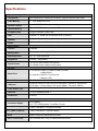
Specifications
System Configuration
CPU(μPGA)
Intel Pentium M / Celeron M Processor, supports 400/533 MHz FSB
Cash Memory
2nd level depend on CPU
System Chipset
Intel 915 GME+ICH6
System Memory
Default 256MB, maximum up to 2 GB
Compact Flash
Support Compact Flash Card
HDD
Internal 2.5” 80GB SATA hard disk drive (or above)
Speaker
Integrated 2 stereo 2 watt speakers.
Power
External 120 watt 19Vdc power adapter.
Main Display
Chipset
GMA900
Memory Size
Share system Memory, 32MB
Resolution Size
15” TFT LCD/1024x768
Brightness
250cd/㎡ (Adjustable)
Touch Screen
15” ELO 5-wire resistive touch panel
15” ABON 5-wire resistive touch panel
I/O Port
Serial Port
4 x External: COM1 & COM2 & COM5 (D-SUB)
COM6(RJ-45)
2 x Internal: COM3 for Touch screen.
COM4 for VFD.
Parallel Port
One Bi-directional Parallel Port(D-SUB25)
USB port
Supports 8 USB 2.0 ports for future expansion (3xInternal, 5xExternal)
Front side x 1, Rear sidex4 (12V power USBx1, 5V power USBx1)
Cash drawer port
RJ-11 Single/Dual Cash Drawer port ,12V/24V actuation support.
LAN Port
10/100/1000Mbps Base-T
Audio Port
Line-out
Optional Features
Customer display
VFD Display
8.9” TFT LCD(Resistive Touch/Non-Touch)
2-in-1(MSR +Fingerprint)
Triple Track MSR.+ Fingerprint Reader
2-in-1(MSR +I-Button)
Triple Track MSR.+ I-Button Reader
RFID
Radio Frequency Identification module
Wi-Fi or Bluetooth
Wi-Fi module 802.11 b/g or USB Bluetooth module
3
UPS
Battery pack(5 minutes run time after power loss)
Mechanical and Environment
Construction
Die-casting Housing & Magnesium-Aluminum alloy
Dimensions
389.5(L) x 360.3(W) x 390(H) mm
Housing Color
Housing color: Gray
Front panel cover & Front base cover color: Silver, Red, Gray, Green,
Yellow, Orange
Weight
9 Kg
Operating temperature
EMI/Safety
0 ℃ ~ 35 ℃
(*CPU needs Cooler & silicone heatsink paste*)
CE, RoHS
A Visual Tour of P1000
Before you start, take a few moments to become familiar with P1000.
Front View
LCD Display
MSR/Fingerprint/
I-Button Assembly
USB Port Cover
ATX Power Switch
4
Rear View
WiFi/Bluetoooth Cover
Display Hinge
2nd Display Cover
RFID/HDD Cover
IO Cover
5
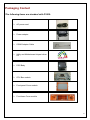
Packaging Content
The following items are standard with P1000:
¾
AC power cord
¾
Power adaptor
¾
COM6 Adaptor Cable
¾
Utility and Motherboard chipset driver
CD
¾
POS Body
¾
CPU Box module
¾
Front panel Cover module
¾
Front base Cover module
6
The following items are optional:
¾
2-in-1 ( Magnetic Stripe Card Reader + Fingerprint Reader )
¾
2-in-1 (Magnetic Stripe Card Reader + I-Button Reader )
¾
2-way choice ( WiFi or Bluetooth )
¾
Radio Frequency Identification (RFID)
¾
Uninterruptible power supply (UPS)
¾
15cm pole VFD customer display
¾
15cm pole 8.9” 2nd display
7
Dimensions
P1000 Dimensions
P1000 and MSR Dimensions
8
P1000 and 15cm 8.9” Pole Display Dimensions
9
P1000 and 15cm VFD Pole Display Dimensions
10
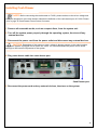
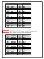
Connector Panels
Primary Connector Panel
The primary connector panel is located at the bottom of the base.
1 2 3 4
ITEM
I/O Port
5
6
Connector Type
7
8
9 10 11 12
Description
1
Audio Line Out
2
POWER
DC Power Connector
Connects P1000 to the power supply.
3
LAN
LAN RJ-45 Connector
It is a Giga LAN port which is used to hook P1000
to a local area network.
4
COM6
RJ-45 Connector
5
COM5
DSUB Connector
6
5V Power USB
Power USB Connector
7
LPT1
Parallel Connector
8
12V Power USB
Power USB Connector
9
COM2
DSUB Connector
10
USBX2
USB Connector
11
COM1
DSUB Connector
12
Cash Drawer
RJ-11 Connector
2 PIN Socket
This port connects an external audio output device.
The serial port COM6 can be used to connect
serial devices such as a mouse or a VFD customer
display.
The serial ports COM5 can be used to connect
serial devices such as a mouse or a fax/modem.
USB port with 5V for USB peripherals. It can
reduce cable.
The parallel port LPT1 can be used to connect
parallel devices, such as a printer.
USB port with 12V for USB peripherals. It can
reduce cable.
The serial ports COM2 can be used to connect
serial devices such as a mouse or a fax/modem.
The USB (Universal Serial Bus) port can be used
to connect USB devices.
The serial ports COM1 can be used to connect
serial devices such as a mouse or a fax/modem.
Cash Drawer Connector, 12 V or 24V Actuation
support for solenoid.
11
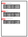
Second Connector Panel
The second connector panel is located on the front side of the base.
1
ITEM
1
2
2
I/O Port
Connector Type
USB
USB TYPE A
Power Button
w/LED
POWER SWITCH
Description
The USB (Universal Serial Bus) port can be used
to connect USB devices.
ATX Power Switch function.
The LED standers power on or power off.
(Green: ON / Dark : OFF).
12
Chapter 2
Hardware Setup
P1000 Assembly
Warnings and Cautions
Before performing hardware upgrades be sure to carefully read all of the applicable instructions,
cautions, and warnings in this guide.
WARNING! To reduce the risk of personal injury from electrical shock, hot surfaces, or fire:
Disconnect the power cord from the wall outlet and allow the internal system components to cool before
touching.
Do not plug telecommunications or telephone connectors into the network interface controller receptacles.
Do not disable the power cord grounding plug. The grounding plug is an important safety feature.
Plug the power cord in a grounded (earthed) outlet that is easily accessible at all times.
CAUTION: Static electricity can damage the electrical components of the computer or optional
equipment. Before beginning these procedures, ensure that you are discharged of static electricity by
briefly touching a grounded metal object.
When the computer is plugged into an AC power source, voltage is always applied to the main board.
You must disconnect the power cord from the power source before opening the computer to prevent
damage to internal components.
13
Installing CPU box
1. Remove all removable media, such as compact discs, from the system unit.
2. Turn off the system power properly through the operating system, then turn off any
external devices.
3. Disconnect the power cord from the power outlet and disconnect any external devices.
CAUTION: To prevent loss of work and damage to the system or drive:
If you are inserting or removing a drive, shut down the operating system properly, turn off the system, and
unplug the power cord. Do not remove a drive while the system is on or in standby mode.
Before handling a drive, ensure that you are discharged of static electricity. While handling a drive, avoid
touching the connector.
4. Push the CPU box into the base of system, and ensure that the CPU box is fully docked
with the internal connector at the back of system unit.
5. Raise the handle, as indicated, and make sure that the 2 thumb screws, as shown, are
locked..(The 2 thumb screws are placed in Accessory box.)
14
6. Attach the Magnetic front base cover into system unit.
7. Connect the power cord and any external devices, then turn on the system.
15
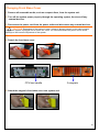
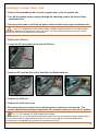
Changing Front Panel Cover
1. Remove all removable media, such as compact discs, from the system unit.
2. Turn off the system power properly through the operating system, then turn off any
external devices.
3. Disconnect the power cord from the power outlet and disconnect any external devices.
CAUTION: Regardless of the power-on state, voltage is always present on the main board as
long as the system is plugged into an active AC outlet. You must disconnect the power cord to avoid
damage to the internal components of the system.
4. Release 4 screws that secure the front panel cover to the system unit.
5. Detach the front panel cover from system unit.
4 magnets
16
6. Attach the Magnetic front panel cover into system unit.
7. Press the front panel cover into place completely.
8. Replace 4 screws that secure the front panel cover to the system unit.
17
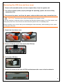
Changing Front Base Cover
1. Remove all removable media, such as compact discs, from the system unit.
2. Turn off the system power properly through the operating system, then turn off any
external devices.
3. Disconnect the power cord from the power outlet and disconnect any external devices.
CAUTION: Regardless of the power-on state, voltage is always present on the main board as
long as the system is plugged into an active AC outlet. You must disconnect the power cord to avoid
damage to the internal components of the system.
4. Detach the front base cover.
CPU box handle
3 magnets
5. Attach the magnetic front base cover into system unit.
18
Removing the CPU box and box cover
1. Remove all removable media, such as compact discs, from the system unit.
2. Turn off the system power properly through the operating system, then turn off any
external devices.
3. Disconnect the power cord from the power outlet and disconnect any external devices.
CAUTION: To prevent loss of work and damage to the system or drive:
If you are inserting or removing a drive, shut down the operating system properly, turn off the system, and
unplug the power cord. Do not remove a drive while the system is on or in standby mode.
Before handling a drive, ensure that you are discharged of static electricity. While handling a drive, avoid
touching the connector.
4. Detach the front base cover.
5. Remove 2 thumb screws that secure the CPU box.
6. Pull out the CPU box.
7. Remove 2 screws on the rear of CPU box that secure the cover to the box chassis.
19
8. Slide the CPU box cover then lift it off the box unit .
1
2
Replacing the CPU box cover
1. Place the CPU box cover on the chassis in front of the final position and slide it back into
place until it stops.
2
1
2. Replace the 2 screws that secure the CPU box cover to the chassis.
20
Installing UPS
1. Remove all removable media, such as compact discs, from the system unit.
2. Turn off the system power properly through the operating system, then turn off any
external devices.
3. Disconnect the power cord from the power outlet and disconnect any external devices.
CAUTION: To prevent loss of work and damage to the system or drive:
If you are inserting or removing a drive, shut down the operating system properly, turn off the system, and
unplug the power cord. Do not remove a drive while the system is on or in standby mode.
Before handling a drive, ensure that you are discharged of static electricity. While handling a drive, avoid
touching the connector.
4. Remove the CPU box and CPU box cover.
5. Secure battery holder with 2 screws, and place the rubber battery support.
6. Put the battery pack into battery box, and locate the battery pack power cable.
7. Connect the battery pack to CN14 and ensuring correct polarity.
CN14
21
NOTE: Before connecting the battery connector cable to main board, please refer to page 32
External BAT connector pin description.
8. Secure battery box cover with 2 screws.
9. Replace CPU box cover and CPU box.
10. Replace the front base cover.
11. Reconnect the power cord and any external devices, then turn on the system.
22
Installing Additional Memory Card
The memory sockets on the main board can be populated with up to two industry-standard DIMMs.
These memory sockets are populated with at least one preinstalled DIMM. To achieve the
maximum memory support, you can populate the main board with up to 2-GB of memory.
Populating DIMM Sockets
There are two DIMM sockets on the main board. The sockets are labeled CN2 and CN3.
1
2
ITEM
1
2
Description
CN2 socket
Socket Color
Black
CN3 socket (populate first)
Black
Installing DIMMs
CAUTION: You must disconnect the power cord and wait approximately 30 seconds for the
power to drain before adding or removing memory modules. Regardless of the power-on state, voltage is
always supplied to the memory modules as long as the system is plugged into an active AC outlet. Adding
or removing memory modules while voltage is present may cause irreparable damage to the memory
modules or main board. If you see an LED light on the main board, voltage is still present.
The memory module sockets have gold-plated metal contacts. When upgrading the memory, it is
important to use memory modules with gold-plated metal contacts to prevent corrosion and/or oxidation
resulting from having incompatible metals in contact with each other.
Static electricity can damage the electronic components of the system or optional cards. Before
beginning these procedures, ensure that you are discharged of static electricity by briefly touching a
grounded metal object.
When handling a memory module, be careful not to touch any of the contacts. Doing so may damage
the module.
23
1. Remove all removable media, such as compact discs, from the system unit.
2. Turn off the system power properly through the operating system, then turn off any
external devices.
3. Disconnect the power cord from the power outlet and disconnect any external devices.
CAUTION: Regardless of the power-on state, voltage is always present on the main board as
long as the system is plugged into an active AC outlet. You must disconnect the power cord to avoid
damage to the internal components of the system.
4. Remove the CPU box and CPU box cover.
NOTE: If the system is installed UPS, must first be removed battery connector and battery pack
away, finally able to see memory sockets. Please refer to page 21 Installing UPS.
5. Locate the memory sockets on the main board.
WARNING! To reduce risk of personal injury from hot surfaces, allow the internal system
components to cool before touching.
6. Insert the memory module into the socket, and push the module down, ensuring that the
module is fully inserted and properly seated. Make sure the latches are in the closed
position.
2
1
NOTE: A memory module can be installed in only one way. Match the notch on the module with
the tab on the memory socket.
7. Repeat step 6 install any additional modules.
8. Replace the CPU box cover and CPU box.
9. Replace the front base cover.
10. Reconnect the power cord and any external devices, then turn on the system. The
system should automatically recognize the additional memory when you turn on the
system.
24
Removing and Replacing the SATA Hard Disk
NOTE: The system does not support Parallel ATA (PATA) hard drives.
Before you remove the old hard drive, be sure to back up the data from the old hard drive so that you
can transfer the data to the new hard drive. Also, if you are replacing the primary hard drive, make sure
you have a Recovery Disc Set to restore the operating system, software drivers, and any software
applications that were preinstalled on the system.
1. Remove all removable media, such as compact discs, from the system unit.
2. Turn off the system power properly through the operating system, then turn off any
external devices.
3. Disconnect the power cord from the power outlet and disconnect any external devices.
CAUTION: Regardless of the power-on state, voltage is always present on the main board as
long as the system is plugged into an active AC outlet. You must disconnect the power cord to avoid
damage to the internal components of the system.
4. Remove 2 screws and unplug HDD cover.
5. Remove 2 screws that secure the HDD tray holder, and pull out the HDD box.
HDD box
6. Remove 4 screws at both sides, and remove the hard disk.
25
7. Replace new Hard Disk to the HDD tray holder, and secure the screw.
8. Insert the HDD box into the socket, ensuring that the HDD box is fully inserted and
properly seated.
9. Replace 2 screws that secure the HDD tray holder.
10. Replace the HDD cover and 2 screws.
11. Reconnect the power cord and any external devices, then turn on the system.
26
Installing Compact Flash Card
1. Remove all removable media, such as compact discs, from the system unit.
2. Turn off the system power properly through the operating system, then turn off any
external devices.
3. Disconnect the power cord from the power outlet and disconnect any external devices.
CAUTION: Regardless of the power-on state, voltage is always present on the main board as
long as the system is plugged into an active AC outlet. You must disconnect the power cord to avoid
damage to the internal components of the system.
4. Remove the CPU box.
5. Locate the CF card socket in the side of CPU box.
6. Insert the CF card into the socket, until the card back button up.
7. Replace the CPU box.
8. Replace the front base cover.
9. Reconnect the power cord and any external devices, then turn on the system. The
system should automatically recognize the CF card device when you turn on the system.
NOTE: CF card and 2.5” HDD master/slave setting:
P1000 allow the use of CF card and hard disk at the same time, but user need to set the system BIOS to
boot the order. When P1000 installed only the CF card, or just install 2.5 "hard disk, BIOS will be
automatically be designated as a 'master' as a system boot device.
27
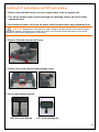
Installing MSR/Fingerprint/I-Button module
An optional 2-in-1(Magnetic Stripe Reader + Fingerprint Reader) or 2-in-1(Magnetic Stripe Reader
+ I-Button Reader) can be installed on the right side of P1000.
1. Remove all removable media, such as compact discs, from the system unit.
2. Turn off the system power properly through the operating system, then turn off any
external devices.
3. Disconnect the power cord from the power outlet and disconnect any external devices.
CAUTION: Regardless of the power-on state, voltage is always present on the main board as
long as the system is plugged into an active AC outlet. You must disconnect the power cord to avoid
damage to the internal components of the system.
4. Remove the 2 screws and expansion cover that on rear of the main unit.
5. Plug the MSR.
MSR top view
MSR bottom view
6. Replace the 2 screws that secure the MSR to the main unit.
7. Reconnect the power cord and any external devices, then turn on the system.
28
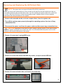
Installing 8.9” pole display and VFD pole display
1. Remove all removable media, such as compact discs, from the system unit.
2. Turn off the system power properly through the operating system, then turn off any
external devices.
3. Disconnect the power cord from the power outlet and disconnect any external devices.
CAUTION: Regardless of the power-on state, voltage is always present on the main board as
long as the system is plugged into an active AC outlet. You must disconnect the power cord to avoid
damage to the internal components of the system.
4. Remove 2 thumb screw and IO cover.
5. Remove the screw and secondary display cover.
6. Secure pole display module.
VFD 15cm pole display
8.9” 15cm pole display
29
7. Replace the I/O Cover and thumb screws.
8. Reconnect the power cord and any external devices, then turn on VFD/LCD power,
Finally, turn on the system power.
30
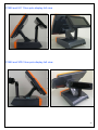
P1000 and 8.9” 15cm pole display full view
P1000 and VFD 15cm pole display full view
31
Installing Cash Drawer
NOTE: Before connecting the cash drawer to P1000, please make sure the driver voltage and
cable pin assignment of the cash drawer matches the definition of the cash drawer port of P1000. Please
refer to page 36 Cash Drawer Power Select Connector.
1. Remove all removable media, such as compact discs, from the system unit.
2. Turn off the system power properly through the operating system, then turn off any
external devices.
3. Disconnect the power cord from the power outlet and disconnect any external devices.
CAUTION: Regardless of the power-on state, voltage is always present on the main board as
long as the system is plugged into an active AC outlet. You must disconnect the power cord to avoid
damage to the internal components of the system.
4. Plug cash drawer cable into cash drawer port.
Cash Drawer port
5. Reconnect the power cord and any external devices, then turn on the system.
32
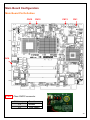
Main Board Configuration
Main Board Pin Definition
CN10
CN15
CN13
CN1
CN14
CN1
Clear CMOS connector
CN1 Jumper
1-2
2-3
1 2 3
Function
Default
Clear CMOS
33
CN14
External BAT connector
PIN No.
1
2
3
CN10
BAT_T+
GND
Description
FAN_IO1
FAN1_12V
FAN_PWM1
CN10
3 2 1
CN15
3 2 1
System Fan connector
PIN No.
1
2
3
CN13
Description
BAT+
CPU Fan connector
PIN No.
1
2
3
CN15
3 2 1
Description
FAN_IO2
FAN2_12V
FAN_PWM2
Power Button connector
PIN No.
1
2
3
4
Description
+V5SB
PANSWIN
+V3.3
GND
4321
34
Clearing CMOS
1. Remove all removable media, such as compact discs, from the system unit.
2. Turn off the system power properly through the operating system, then turn off any
external devices.
3. Disconnect the power cord from the power outlet and disconnect any external devices.
CAUTION: Regardless of the power-on state, voltage is always present on the main board as
long as the system is plugged into an active AC outlet. You must disconnect the power cord to avoid
damage to the internal components of the system.
4. Remove the CPU box and CPU box cover.
5. Locate CN1 connector on the main board.
CN1 Jumper
NOTE: Before setting jumper in the CN1 connector. Please refer to page 33 CN1 Jumper
Function.
6. Replace the CPU box cover and CPU box.
9. Reconnect the power cord and any external devices, then turn on the system.
35
I/O Board Configuration
The IOTR board transform signals form main board to TOP IO board and Bottom IO board.
IOTR Board Pin Definition
Top side faces the PC box
Locate the Power I/O Jumpers inside
the System case.
MD_1
J1
MD_2
J2
IO_BUS1
J1
J3
IO_BUS2
Cash Drawer Power Select Connector
PIN No.
1
2
3
Description
12V
Drawer Power Select
24V
Select Cash Drawer Power as shown in the table
1-2 Short
2-3 Short
J1
12V (Default)
24V
36
J2
COM1 & COM2 Power Select Connector
PIN No.
1
2
3
4
5
6
J3
Description
5V
RIA
RI_A
RIA
12V
RIA
PIN No.
7
8
9
10
11
12
Description
5V
RIB
RI_B
RIB
12V
RIB
COM5 & COM6 Power Select Connector
PIN No.
1
2
3
4
5
6
Description
5V
RIE
RI_E
RIE
12V
RIE
PIN No.
7
8
9
10
11
12
Description
5V
RIF
RI_F
RIF
12V
RIF
Select COM Port Power as shown in the table
Connector
COM Port
COM1
J2
COM2
COM5
J3
COM6
Connect
3-4
1-2
5-6
9-10
7-8
11-12
3-4
1-2
5-6
9-10
7-8
11-12
Description
RI*
+5V
+12V
RI*
+5V
+12V
RI*
+5V
+12V
RI*
+5V
+12V
(Default: RI* signal)
37
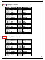
MD_1
Display I/O Connector
PIN No.
1
3
5
7
9
11
13
15
17
19
21
23
25
27
29
31
33
35
37
39
MD_2
Description
SPK_R+
SPK_RPVDD
RXO0RXO1GND
RXO2RXOCLKGND
RXO3GND
12V
12V
12V
UD5GND
UD65V
NC
KB-CK
PIN No.
2
4
6
8
10
12
14
16
18
20
22
24
26
28
30
32
34
36
38
40
Description
GND
GND
PVDD
RXO0+
RXO1+
GND
RXO2+
RXOCLK+
GND
RXO3+
GND
ON/OFF
LCD_ADJ
GND
UD5+
GND
UD6+
5V
NC
KB-DA
PIN No.
2
4
6
8
10
12
14
16
18
20
22
24
Description
SPK_L5V
5V
5V
12V
UD7+
SA0_TXN
GND
SA0_RXP
GND
GND
GND
Display I/O Connector
PIN No.
1
3
5
7
9
11
13
15
17
19
21
23
Description
SPK_L+
5V
5V
5V
12V
UD7SA0_TXP
GND
SA0_RXN
TX_C
RX_C
RTS_C
38
25
27
29
IO_BUS1
CTS_C
DSR_C
DTR_C
26
28
30
GND
GND
GND
IO_BUS2
I/O BUS1(164 PIN) & IO BUS2 (64 PIN) PCI Express Connector connect to the
main board GF1 & GF2.
Bottom side faces the I/O Connector
2ND_DISPLAY
PIN No.
A1
A2
A3
A4
A5
A6
A7
A8
A9
A10
A11
A12
A13
Second Display 36 PIN PCI Express Connector
Description
DSR_D
RTS_D
TX_D
GND
GND
NC
12V
12V
12V
12V
12V
GND
GND
PIN No.
B1
B2
B3
B4
B5
B6
B7
B8
B9
B10
B11
B12
B13
Description
DTR_D
CTS_D
RX_D
GND
GND
GND
GND
NC
5V
5V
5V
GND
GND
39
A14
A15
A16
A17
A18
TOP_BUS
PIN No.
A1
A2
A3
A4
A5
A6
A7
A8
A9
A10
A11
A12
A13
A14
A15
A16
A17
A18
A19
A20
A21
A22
A23
A24
A25
A26
A27
A28
A29
A30
DDCCLK
DDCDAT
BLUE
GRN
RED
B14
B15
B16
B17
B18
VSYNC
HSYNC
GND
GND
GND
TOP_BUS 98 PIN PCI Express Connector connects to the
TOP IO board TOP_BUS Golden Finger.
Description
GND
GND
NC
DTR_D
DSR_D
CTS_D
RTS_D
RX_D
TX_D
NC
GND
5V
5V
5V
5V
NC
GND
GND
GND
GND
GND
GND
GND
LAN_L2LAN_L2+
LAN_L1LAN_L1+
LAN3LAN3+
LAN2-
PIN No.
B1
B2
B3
B4
B5
B6
B7
B8
B9
B10
B11
B12
B13
B14
B15
B16
B17
B18
B19
B20
B21
B22
B23
B24
B25
B26
B27
B28
B29
B30
Description
GND
GND
VSYNC
HSYNC
DDCCLK
DDCDAT
BLUE
GRN
RED
GND
GND
12V
12V
12V
12V
NC
GND
LINE_HP
LINEO_L
LINEO_R
GND
GND
GND
GND
UD4+
UD4GND
UD3+
UD3GND
40
A31
A32
A33
A34
A35
A36
A37
A38
A39
A40
A41
A42
A43
A44
A45
A46
A47
A48
A49
BTM_BUS
PIN No.
A1
A2
A3
A4
A5
A6
A7
A8
A9
A10
A11
A12
A13
A14
A15
LAN2+
LAN1LAN1+
LAN0LAN0+
GND_LAN
GND
IN_0
5V
5V
5V
5V
NC
12V
12V
12V
12V
12V
12V
B31
B32
B33
B34
B35
B36
B37
B38
B39
B40
B41
B42
B43
B44
B45
B46
B47
B48
B49
UD2+
UD2GND
UD1+
UD1GND
OUT1
OUT0
Drawer Power Select
Drawer Power Select
NC
GND
GND
GND
GND
GND
GND
GND
GND
BTM_BUS 98 PIN PCI Express Connector connects to the
BOTTOM IO board BTM_BUS Golden Finger.
Description
GND_FIELD
GND_FIELD
GND_FIELD
GND_FIELD
GND_FIELD
GND_FIELD
GND_FIELD
GND_FIELD
GND_FIELD
GND_FIELD
GND_FIELD
DTR_F
DSR_F
CTS_F
RIF
PIN No.
B1
B2
B3
B4
B5
B6
B7
B8
B9
B10
B11
B12
B13
B14
B15
Description
DC_IN
DC_IN
DC_IN
DC_IN
DC_IN
DC_IN
DC_IN
DC_IN
DC_IN
DC_IN
DC_IN
RX_F
TX_F
DCD_F
RTS_F
41
A16
A17
A18
A19
A20
A21
A22
A23
A24
A25
A26
A27
A28
A29
A30
A31
A32
A33
A34
A35
A36
A37
A38
A39
A40
A41
A42
A43
A44
A45
A46
A47
A48
A49
RIE
DTR_E
DSR_E
CTS_E
GND
GND
PPE
PACKX
PD6
PD4
PSLINX
PINITX
PERX
PAFDX
GND
GND
NC
12V
12V
12V
12V
NC
GND
GND
GND
GND
RIB
CTS_B
RTS_B
DSR_B
RIA
DTR_A
DSR_A
CTS_A
B16
B17
B18
B19
B20
B21
B22
B23
B24
B25
B26
B27
B28
B29
B30
B31
B32
B33
B34
B35
B36
B37
B38
B39
B40
B41
B42
B43
B44
B45
B46
B47
B48
B49
RTS_E
RX_E
TX_E
DCD_E
GND
PSLCT
PBUSY
PD7
PD5
PD3
PD2
PD1
PD0
PSTBX
GND
GND
NC
5V
5V
5V
5V
NC
GND
GND
GND
GND
DTR_B
TX_B
RX_B
DCD_B
RTS_A
RX_A
TX_A
DCD_A
42
Top IO Board Pin Definition
TOP IO board covers the I/O ports to the IOTR board. Including: audio port, LAN, Cash Drawer,
5V power USB,12V power USB,USB.
LINE_OUT
Audio line output EAR Connector
PIN No.
1
2
3
4
5
LAN
Description
GND_SP
LO_R
LO_L
LO_HP
NC
RJ-45 LAN Port
PIN No.
1
3
5
7
P_USB2
Description
LAN0+
LAN1+
LAN2LAN3+
PIN No.
2
4
6
8
Description
LAN0LAN2+
LAN1LAN3-
PIN No.
2
4
6
8
Description
UD2GND
5V
GND
5V Power USB Port
PIN No.
1
3
5
7
Description
5V
UD2+
GND
5V
43
P_USB1
12V Power USB Port
PIN No.
1
3
5
7
USB_B1
PIN No.
2
4
6
8
Description
UD1GND
12V
GND
PIN No.
2
4
6
8
Description
UD3GND
UD4GND
USB Port
PIN No.
1
3
5
7
DRAW
Description
5V
UD1+
GND
12V
Description
5V
UD3+
5V
UD4+
RJ-11 Cash drawer Port
PIN No.
1
3
5
Description
GND
IN_0
DGO_1
PIN No.
2
4
6
Description
DGO_0
V_DRAW
GND
44
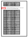
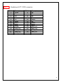
Bottom IO Board Pin Definition
BOTTOM IO board covers the I/O ports to the IOTR board. Including: DC IN, RJ-45 COM6, COM1,
COM2, COM5, LPT1.
J1
COM6&VFD select Connector
PIN No.
1
3
5
Description
RTS_F
RTSF
GND
PIN No.
2
4
6
Description
CTS_F
CTSF
RI_F
COM6
COM6 uses the RJ-45 connector to accept VFD customer display. If the customer
display is not required, this port may function as an RS-232C port. An adapter cable
to convert RJ-45 to DB-9 is placed in accessory box. Jumpers on the circuit board
must also be reconfigured as shown in the table.
Mode1 RJ-45 connector used for RS232 device (Default)
J3( IOTR board)
7-8
Short (+5V)
J1(Bottom IO board)
1-3
Short
2-4
Short
RJ-45 Pin definitions
PIN No.
1
3
5
7
Description
+5V
GND
DTRF
TXF
PIN No.
2
4
6
8
Description
CTSF
RTSF
DSRF
RXF
45
Mode2 RJ-45 connector used for VFD device
J1(Bottom IO board)
3-5
Short
4-6
Short
J3( IOTR board)
11-12
Short (+12V)
RJ-45 Pin definitions
PIN No.
1
3
5
7
DC_IN1
Description
+12V
GND
DTRF
TXF
PIN No.
2
4
6
8
Description
+12V
GND
DSRF
RXF
DC Power Jack connector
PIN No.
1
2
3
4
Description
GND
DC_IN
GND
DC_IN
COM1&COM2&COM5
PIN No.
1
2
3
4
5
6
7
8
9
RS232 port COM1,COM2 and COM5 D-SUB connector
Description
DCD
RX
TX
DTR
GND
DSR
RTS
CTS
RI
Pin9 signal can be selected as standard RI or DC power output depending on the IOTR board J2
and J3 jumper settings. The default settings are for RI.
46
LPT1
Parallel port LPT1 SCSI connector
PIN No.
1
3
5
7
9
11
13
15
17
19
21
23
25
Description
STBX
D1
D3
D5
D7
BUSY
SLCT
ERX
SLINX
GND_LPT
GND_LPT
GND_LPT
GND_LPT
PIN No.
2
4
6
8
10
12
14
16
18
20
22
24
Description
D0
D2
D4
D6
ACKX
PE
AFDX
INITX
GND_LPT
GND_LPT
GND_LPT
GND_LPT
47
Chapter 3
Software Setup
Driver Software List
Driver
Driver Setup Location
Intel Chipset
<CD>:\Driver\Intel INF\PWI-M91x
Intel Graphics
<CD>:\Driver\VGA\PWI-M91x
ELO Touch Screen
<CD>:\Driver\Touch\Elo
Abon Touch Screen
<CD>:\Driver\Touch\Abon
RealTek Audio
<CD>:\Driver\Audio\RealTek AC97
PCIe GigaBit LAN
<CD>:\Driver\LAN\PCIe_GLAN
802.11b/g Wireless
<CD>:\Driver\WLAN\802.11bg
USB RFID
<CD>:\Driver\RFID\USB driver
Fingerprint Reader
<CD>:\Driver\FingerPrint\UareU\DP Plat frsw 3.2
Cash Drawer and UPS
<CD>:\Driver\System
OPOS
<CD>:\Driver\OPOS
48
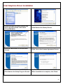
Intel Chipset Driver Installation
1.Locate and Run the Setup.exe file on the
CD in folder <CD>:\Intel INF\PWI-M91x
2.Click the Next button on the Welcome
Screen.
3.Click Yes on the License Agreement
Screen.
4.Click Next on the Information Screen.
-----
5.When Installation is complete, click
Finish.
-----
49
Intel Graphics Driver Installation
1.Locate and Run the win2k_xp1425.exe
file on the CD in folder <CD>:\VGA
Driver\PWI-M91x
2.Click Next on the Startup Screen.
3.Click the Next button on the Welcome
Screen.
4.Click Yes on the License Agreement Screen.
5.Click Next on the Setup Progress Screen. 6.When Installation is complete, click Finish.
50
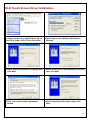
ELO Touch Screen Driver Installation
1.Locate and Run the sw600188.exe file on
the CD in folder <CD>:\Touch Driver\Elo
2.Click Unzip on the WinZip Self-Extractor
Window.
3.Select Default Installation Language then
click Next.
4.Select Install Serial Touchscreen Drivers and
then click Next.
5.Click Yes on the License Agreement
Screen.
6.Select Auto-Detect Elo Device then click
Next.
51
7.Select COM3 then click Next.
8.Click Next.
9.When Installation is complete, click
Finish and Restart the System.
10.After the computer has restarted, click
Align on the Elo Touchscreen Properties
Screen.
-----
11.Calibrate the three red points as
instructed.
-----
52
Audio Driver Installation
1.Locate and Run the WDM_A381.exe file
on the CD in folder <CD>:\Audio
Driver\RealTek AC97
2.Click Next on the Welcome Screen.
3.Click Continue Anyway on Hardware
Installation Screen.
4.When Installation is complete, click Finish.
53
Gigabit LAN Driver Installation
1.Locate and Run the Setup.exe file on the
CD in folder <CD>:\LAN Driver\PCIe_GLAN
2.Select Modify then click Next.
3.Select DefaultFeature and click Next.
4.Click Continue Anyway on Hardware
Installation Screen.
-----
5.When Installation is complete, click
Finish.
-----
54
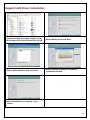
Wireless LAN Driver Installation (optional)
1.First, plug in USB WLAN Interface Module.
2.Locate and Run the Setup.exe file on the CD
in folder <CD>:\ Driver\WLAN\ 802.11bg
3.Click Next on the License Agreement Screen.
4.Select Ralink Configuration Tool then
click Next.
5.Select Optimize WiFi mode then click Next.
6.Click Install.
7.Click Continue Anyway on Hardware
Installation Screen.
-----
8.When Installation is complete, click
Finish.
-----
55
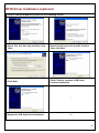
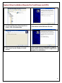
RFID Driver Installation (optional)
1.Plug in USB RFID Module and wait for the following screen.
2.Select Yes, this time only and then click
Next.
3.Select Install from a list specific location
then click Next
4.Click Next
5.Click Finish to complete USB Serial
Converter Installation
-----
6.Repeat for USB Serial Port Installation
-----
56
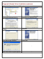
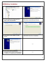
Fingerprint Reader Driver Installation (optional)
1.Plug in 2 in 1 Fingerprint Reader and MSR module.
2.Locate and Run the Setup.exe file in folder <CD>:\
Driver\FingerPrint\UareU\DP Plat frsw 3.2
3.Click Next on the Welcome Screen.
4.Click Next on the License Agreement
Screen.
5.Click Next.
6.Click Next to begin Installation.
7.Click Finish.
-----
8.Click Yes to restart the system (required)
-----
57
System Driver Installation (Required for Cash Drawer and UPS)
1. Locate and Run the Setup.exe file in
folder <CD>:\Driver\System
2. Click Next on the Welcome Screen.
3. Click Install on the Ready to Install
screen.
4. Click Finish on the Installation Complete
Screen. Note a system restart is required to
complete the Installation.
58
OPOS Driver Installation
1. Locate and Run the Setup.exe file in
folder <CD>:\Driver\OPOS
2. Click Next on the Welcome Screen.
3. Click Install on the Ready to Install
screen.
4. Wait while the driver is installed.
-----
5. Click Finish on the Installation
Complete Screen. Note a system restart
is required to complete the Installation.
-----
59
MSR Driver Installation (optional)
1. First, plug-in 2 in 1 Fingerprint Reader and MSR module.
2. Reboot system to complete installation.
60
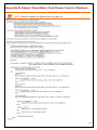
Appendix A. Sample C++ Cash Drawer Code for Windows
NOTE: Requires installation of System Driver (see page 58).
1.Open Cash Drawer
// IOCTL Codes
#define GPD_TYPE 56053
#define ADV_OPEN_CTL_CODE CTL_CODE(GPD_TYPE, 0x920, METHOD_BUFFERED, FILE_ANY_ACCESS)
#define ADV_STATUS_CTL_CODE CTL_CODE(GPD_TYPE, 0x900, METHOD_BUFFERED, FILE_ANY_ACCESS)
void OpenDrawer(UCHAR uWhichDrawer) // uWhichDrawer = 1 => CD#1, uWhichDrawer = 2 => CD#2
{
HANDLE hFile;
BOOL bRet
UCHAR uDrawer = uWhichDrawer;
// Open the driver
hFile = CreateFile(TEXT("\\\\.\\ADVSYS"),
GENERIC_WRITE | GENERIC_READ,
FILE_SHARE_READ | FILE_SHARE_WRITE, NULL,
OPEN_EXISTING, FILE_ATTRIBUTE_NORMAL, 0);
if (m_hFile == INVALID_HANDLE_VALUE)
{
AfxMessageBox("Unable to open Cash Drawer Device Driver!");
return;
}
// Turn on the Cash Drawer Output (Fire the required solenoid)
bRet = DeviceIoControl(hFile, ADV_CD_OPEN_CTL_CODE,
&uDrawer, sizeof(uDrawer),
NULL, 0,
&ulBytesReturned, NULL);
if (bRet == FALSE || ulBytesReturned != 1)
{
AfxMessageBox("Failed to write to cash drawer driver");
CloseHandle(hFile);
return;
}
CloseHandle(hFile);
}
2.Get Cash Drawer Status
void GetDrawerState()
{
HANDLE hFile;
BOOL bRet
UCHAR uDrawer = uWhichDrawer;
// Open the driver
hFile = CreateFile(TEXT("\\\\.\\ADVSYS"),
GENERIC_WRITE | GENERIC_READ,
FILE_SHARE_READ | FILE_SHARE_WRITE, NULL,
OPEN_EXISTING, FILE_ATTRIBUTE_NORMAL, 0);
if (m_hFile == INVALID_HANDLE_VALUE)
{
AfxMessageBox("Unable to open Cash Drawer Device Driver!");
return;
}
// Read the CD status
bRet = DeviceIoControl(hFile, ADV_CD_STATUS_CTL_CODE,
NULL, 0
&ReadByte, sizeof(ReadByte),
&ulBytesReturned, NULL);
if (bRet == FALSE || ulBytesReturned != 1)
{
AfxMessageBox("Failed to Read from cash drawer driver");
CloseHandle(hFile);
return;
}
else
{
AfxMessageBox(ReadByte ? “Drawer Open” : “Drawer Closed”);
}
CloseHandle(hFile);
}
61
Appendix B. Sample Visual Basic Cash Drawer Code for Windows
NOTE: Requires installation of System Driver (see page 58).
62