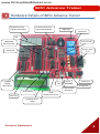
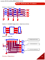
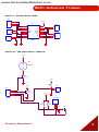
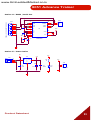
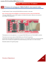
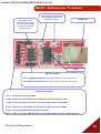
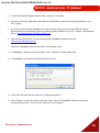
1
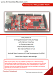
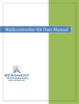
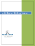
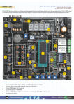
www.EmbeddedMarket.com
8051 Advance Trainer
On Board Features of 8051 AdvanceTrainer with P89V51RD2 Microcontroller
1.
2.
3.
4.
5.
6.
7.
8.
9.
RS232 interface
38KHZ RC5 IR receiver
Buzzer
Light Sensor (LDR)
Temperature Sensor
Three Analog Inputs via presets
All port open 89V51RD2 Microcontroller
Four 7-Segment Display
Real time clock with DS1307
Product Datasheet
10. EEPROM 24C256
11. Eight LEDs
12. Two Relays
13. Four Switches
14. Eight bit Analog to Digital Converter
15. Matrix keypad 4x4
16. Stepper Motor driver ULN2803
17. LCD 16 character by 2 lines
18. DC Motor Driver L293D
1
www.EmbeddedMarket.com
8051 Advance Trainer
Sr.
Num.
Topics
Page
1
About 8051 Advance Trainer
3
2
Hardware Details
4
3
Process to program P89V51RD2 microcontroller
12
4
Important information
16
Product Datasheet
2
www.EmbeddedMarket.com
8051 Advance Trainer
1. About 8051 Advance Trainer
The 8051 Advance Trainer Board is designed for experiments with 89V51RD2 microcontroller which has 8051
core. Use this board as learning board or as experiment board or as product design workbench, it has all that
is required.
There are two types of displays provided, one 16x2 alphanumeric LCD and other is 4 digit multiplexed 7segment LED display. On input side, use the 4x4 matrix keypad and four separate keys.
The board is equipped with RS232 communication, low power demo purpose motor driver circuits and ADC.
The ADC can read external analog input. On board variety of analog sensors are provided such as Light
sensor) LDR, Temperature Sensor (LM35) and manual presets (variable resistance).
Use the on board buzzer to generate bip sound for audio indication. The TSOP1738 on the board detects
38KHz modulated IR input and can function as RC5 IR decoder. This allows remote controlled application
development using 89V51RD2.
There are two advanced interfaces provided, DS1307 Real Time Clock and 24C256 EEPROM. Both are I2C
based interfaces. The 89V51RD2 does not have built-in I2C lines, so a code based on bit-bang method can
interface 89V51RD2 with these two interfaces.
Eight LEDs and Two relays make it complete development package to the board.
Product Datasheet
3
www.EmbeddedMarket.com
8051 Advance Trainer
2. Hardware Details of 8051 Advance Trainer
Multiplexed Seven
Segment LED Display
I2C based DS1307 RTC
and 24C256 EEPROM
Eight LEDs
Two Relays
ADC
P89V51RD2
Microcontroller
Four Switches
RS232 / Serial
Port
4x4 Keypad
Buzzer
ULN2803
Stepper
Motor Driver
9VDC Input
LDR
5V Regulator
Three Presets
16x2 LCD
LM35
Temperature Sensor
TSOP1738 RC5
IR Receiver
DC Motor Driver
L293D
Product Datasheet
4
www.EmbeddedMarket.com
8051 Advance Trainer
Sectional Schematics:
Section 1 – Seven Segment Displays
HEADER 4
3
3
1
Q2
BC548
2
3
Q3
BC548
2
R7
1
1
1
Q4
BC548
2
R8
R9
R10
VCC
VCC
VCC
VCC
JP21
Q1
BC548
2
3
4
3
2
1
.
.
.
.
.
.
.
.
.
.
.
.
.
.
.
.
.
.
.
.
40
39
38
37
36
35
34
33
32
31
30
29
28
27
26
25
24
23
22
21
JP26
U5
HEADER 8
1
2
3
4
5
6
7
8
9
10
11
12
13
14
15
16
17
18
19
20
.
.
.
.
.
.
.
.
.
.
.
.
.
.
.
.
.
.
.
.
40_PIN_IC_BASE
1
2
3
4
5
6
7
8
Product Datasheet
5
www.EmbeddedMarket.com
8051 Advance Trainer
Section 2 – Matrix Keypad
SW16
SW15
SW12
SW11
SW8
SW4
SW14
SW13
SW10
SW9
SW7
SW6
SW5
SW3
SW2
PD0
PD1
PD2
SW1
PD3
PD7
PD6
PD5
PD4
Section 3 – ULN2803 Stepper Motor / High Current Driver
JP27
U8
1
2
3
4
5
6
7
8
9
1
2
3
4
5
6
7
8
8 HEADER
1
2
3
4
5
6
7
8
9
JP28
18
17
16
15
14
13
12
11
10
18
17
16
15
14
13
12
11
10
8
7
6
5
4
3
2
1
VCC
ULN2803
Section 4 – 16x2 LCD
1
2
3
4
5
6
7
8
9
10
11
12
13
14
15
16
JP2
1
2
3
4
5
6
7
8
9
10
11
12
13
14
15
16
FEMALE CONNECTOR
VCC
VCC
JP4
2
1
JP12
R2
1
47K
2
R4
1K
Backlight On/Off Jumper
1
2
3
4
5
6
7
8
Data Lines D0 to D7
Control Lines RS, RW, EN
3
1
2
3
JP18
Product Datasheet
6
www.EmbeddedMarket.com
8051 Advance Trainer
Section 5 – P89V51RD2 Microcontroller with Port Pins Open for Interfacing
VCC
VCC
Reset selector Jumper.
JP1
1
2
3
4
5
6
1
2
3
VCC
HEADER 3
VCC
ISP
JP6
JP5
1
2
3
U3
1
2
3
4
5
6
7
8
1
2
3
4
5
6
7
8
9
10
11
12
13
14
15
16
17
18
19
20
JP16
1
2
3
4
5
6
7
8
C2
Y1
(OCO/TO) PB0
(T1)PB1
(AIN0)PB2
(AIN1)PB3
(SS)PB4
(MOSI)PB5
(MISO)PB6
(SCK)PB7
RESET
(RXD)PD0
(TDX)PD1
(INT0)PD2
(INT1)PD3
(XCK)PD4
(OC1A)PD5
(WR)PD6
(RD)PD7
XTAL2
XTAL1
GND
89 S
VCC
PA0(AD0)
PA1(AD1)
PA2(AD2)
PA3(AD3)
PA4(AD4)
PA5(AD5)
PA6(AD6)
PA7(AD7)
PE0(ICP/INT2)
PE1(ALE)
PE2(OC1B)
PC7(A15)
PC6(A14)
PC5(A13)
PC4(A12)
PC3(A11)
PC2(A10)
PC1(A9)
PC0(A8)
40
39
38
37
36
35
34
33
32
31
30
29
28
27
26
25
24
23
22
21
JP9
1
2
3
4
5
6
7
8
HEADER 3
JP17
1
2
3
1
2
3
4
5
6
7
8
JP19
C3
Section 6 – Presets (Variable resistance)
2
VCC
1
3
2
R19
RESISTOR VAR
1
3
JP33
3
2
1
2
R20
RESISTOR VAR
1
3
R21
RESISTOR VAR
Product Datasheet
7
www.EmbeddedMarket.com
8051 Advance Trainer
Section 7 – I2C Based RTC & EEPROM
VCC
SQW
R261K
U16
1
2
6
U17
.
.
.
.
.
.
.
.
R281K
8
7
6
5
3
8
VCC
ATMEL_U904
1
2
3
VBAT
VCC
DS1307
1
1
2
3
4
X1
X2
SCLK
SDA
SQW/OUT
5
7
GN D
X1
CRYSTAL
R271K
4
VCC
BT1
BATTERY
2
JP32
HEADER 3
Section 8 – ADC0804
VCC
R1
10K
1
2
3
4
5
6
7
8
9
10
C1
150
R3
20K
2
1
2
3
2
1
VCC
U2
.
.
.
.
.
.
.
.
.
.
.
.
.
.
.
.
.
.
.
.
20
19
18
17
16
15
14
13
12
11
OUTPUT
8
7
6
5
4
3
2
1
JP10
ADC804
3
VCC
R5
1
1
2
R6
10K
10K
Product Datasheet
8
www.EmbeddedMarket.com
8051 Advance Trainer
Section 9 – DC Motor Driver L293D
JP5
VCC
1
2
3
U1
1
2
3
4
5
6
7
8
JP6
2
1
JP7
2
1
E1
I1
O1
GND
GND
O2
I2
VS
VSS
I4
O4
GND
GND
O3
I3
E2
JP8
16
15
14
13
12
11
10
9
1
2
1
2
3
JP9
L293D
Section 10 – LDR, LM35, Buzzer, TSOP1738
1
VCC
1
BZ1
1
2
2
BUZZER
Q5
BC547
VCC
3
2
R16
3.3K
VCC
1
2
1
JP37
Q6
LM35
2
LDR
VCC
3
4
3
2
1
JP31
U9
TSOP1738
R18
200E
R17
10K
3
2
1
3
2
1
HEADER 4
C8
Product Datasheet
9
www.EmbeddedMarket.com
8051 Advance Trainer
Section 11 – Switches
1
2
VCC
SW2
1
2
SW3
R22
1K
R23
1
JP8
2
1
2
3
4
SW4
1K
R24
1
2
1K
R25
SW5
HEADER 4
1K
Section 12 – LEDs
VCC
D1
RP3
1
C
JP22
D2
2
3
4
5
6
7
8
9
1
2
3
4
5
6
7
8
D3
D4
D5
D6
D7
1K
8 HEADER
D8
Section 13 – Relays
VCC
VCC
U10
3
D9
4
DIODE
5
.
.
1
.
.
.
2
HEADER 3
U11
1
2
3
3
D10
DIODE
HEADER 1
Q7
BC548
2
1
1
HEADER 1
4
5
.
1
.
.
.
2
HEADER 3
1
2
3
JP35
Q8
BC548
2
3
1
RELAY
3
1
2
1
JH2
1
JP34
.
RELAY
Note - Use 1K resistance in series between the Port Pin of 89V51RD2 and the base pin of BC548 (marked
as R on the board). This resistance is included with the product.
Product Datasheet
10
www.EmbeddedMarket.com
8051 Advance Trainer
Section 14 – RS232 / Serial Port
JP23
F EM ALE C ON N EC T OR D B9
JP24
13
8
11
10
1
6
2
7
3
8
4
9
5
R1IN
R2IN
T1IN
T2IN
1
3
4
5
2
6
C4
C5
VCC
R1OUT
R2OUT
T1OUT
T2OUT
TX
12
9
14
7
VCC
U4
C+
C1C2+
C2V+
V-
1
2
RX
GND
VCC
15
16
MAX232/SO
C6
C7
Section 15 – Power Section
VIN
VCC
VCC
JP93
3
2
1
1
VIN
CONN JACK
GN D
U22
O/P
3
VCC
R37
1K
2
JP94
7805
C31
0.1uF
C28
0.1uF
C30
1000uF
D13
LED
1
2
HEADER 2
Product Datasheet
11
www.EmbeddedMarket.com
8051 Advance Trainer
3. Process to program P89V51RD2 microcontroller
The 8051 Advance Trainer comes with P89V51RD2 microcontroller on the board.
Note –Product pictures shows AT89S52 on the board but the product comes with P89V51RD2
To Program P89V51RD2, use the USB Programmer included with the product. Below are the instructions
about usage of this programmer –
This programmer has dual applications. It can program P89V51RD2 as well as LPC2138 ARM7 controllers.
Thus below notes includes details of P89V51RD2 and for LPC2138 Programming
In both cases, the controllers are programmed “In-Circuit” i.e. the controllers need not to be removed from the
board / circuit. Controllers are programmed and automatically they switch back to run mode once done.
Read below details for Programming steps:
Product Datasheet
12
www.EmbeddedMarket.com
8051 Advance Trainer
Add Jumper here to
connect 5V from USB to
the development Board.
Do not use this jumper
with LPC ARM.
LEDs indicate program being
transmitted from USB to the
development board.
USB B Type
FT232
Selection Jumper:
For LPC ARM Programming: Add Jumper between Left pin and Center.
For P89VXX Programming: Add Jumper between Right pin and Center.
Programming Header:
1. Vcc – 5V (Do not use for LPC ARM)
2. GND- Common Ground between this programmer & the development board
3. RXD – Connect to RX line of the microcontroller. (RX0 in case of LPC ARM)
4. TXD – Connect to TX line of the microcontroller. (TX0 in case of LPC ARM)
5. RST – Connect to RESET line of the microcontroller
6. P0.14 – BSL line for LPC ARM (Optional for LPC ARM and Not required for P89V51RD2 etc)
Product Datasheet
13
www.EmbeddedMarket.com
8051 Advance Trainer
How to Program?
1. On the USB programmer, set jumper to 89V Side, as shown in above picture.
2. Using the 6 pin female to single pin female connector, connect GND, RXD, TXD, RST of the
Programmer to GND, P3.0, P3.1, RST of the 8051 Advance Trainer Board.
On 8051 Advance Board 1. GND is second pin on the connectors marked as ISP
2. P3.0 to RXD
3. P3.1 to TXD
4. RST is sixth pin on the connector marked as ISP
Product Datasheet
14
www.EmbeddedMarket.com
8051 Advance Trainer
3. On the 8051Advance Board, Set RST SEL Jumpers to VCC Side.
4. Connect A to B Type USB cable (also called as USB cable for printer) from the programmer to your
PC / Laptop
5. If you have connected this Programmer for the first time then you may need to install the drivers.
Download the drivers matching with the operating system installed on your PC / Laptop. The download
link is : http://www.ftdichip.com/Drivers/VCP.htm
6. After installing the drivers, you may download the FlashMagic Software from link:
http://www.flashmagictool.com/
7. Install the FlashMagic software and start it from program menu.
8. In FlashMagic, Select the microcontroller’s name, COM Port number, Baud Rate
9. In FlashMagic, click Options=>Advanced Options menu
10. Click OK once done with the selection in “Advanced Options”.
11. Click “Browse” to select the hex file and click “Start” button in FlashMagic software to begin the
Programming process. Hex file is the output file of your program.
Product Datasheet
15
www.EmbeddedMarket.com
8051 Advance Trainer
4. Important information
1. The “8051 Advance Trainer” product is designed for experiments and is not suitable to be used in life support
and mission critical products.
2. Manufactured by:
Embedded Market
205 Decision Tower
Next To CityPride
Satara Road
Pune 411037 India
Ph: +91 20 24228818
For Support- Login to your account at EmbeddedMarket.com and post Support request via Support
request Link
Email for Sales – [email protected]
Website – www.EmbeddedMarket.com
3. For Product Customization & Bulk orders, contact [email protected]
Product Datasheet
16