1
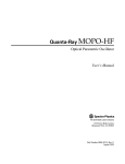
VPC-200 User’s Manual Revision 3.0 – December 3, 2001 2001 Airway Avenue Fort Collins, CO 80524 (970) 224-3898, Fax: (970) 224-3899 Copyright 1997, 1998, 1999, 2001 Paravion Technology, Inc. ALL RIGHTS RESERVED Table of Contents Description ........................................................................................................................................Page 3 UTM Conversion ..............................................................................................................................Page 3 Tilting Field Management ...............................................................................................................Page 3 Quick-Start Operation Information ...............................................................................................Page 3 Specifications ....................................................................................................................................Page 4 Specifications...............................................................................................................................Page 4 Options ..............................................................................................................................................Page 4 General Specifications......................................................................................................................Page 4 VPC Connectors ...............................................................................................................................Page 4 Cabling.........................................................................................................................................Page 5 S-Video ........................................................................................................................................Page 5 Normal Use Connections..................................................................................................................Page 5 Power ...........................................................................................................................................Page 5 Video Source ...............................................................................................................................Page 5 Video Monitor .............................................................................................................................Page 5 VCR .............................................................................................................................................Page 5 GPS Data Connection ..................................................................................................................Page 5 Cabling Cautions .........................................................................................................................Page 5 Video Connections.......................................................................................................................Page 6 S-Video Connections ...................................................................................................................Page 6 The VPC-200 Keyboard...................................................................................................................Page 7 Data Input ....................................................................................................................................Page 7 Positioning the Cursor .................................................................................................................Page 7 Entering Text ...............................................................................................................................Page 7 Editing Text .................................................................................................................................Page 7 Text Background..........................................................................................................................Page 7 Selecting Transparent Test or Opaque Text Mode ......................................................................Page 7 Configuring the VPC-200 ................................................................................................................Page 8 Showing/Exiting the Configuration Page ....................................................................................Page 8 Configuration Field Display ........................................................................................................Page 8 Selecting a Field...........................................................................................................................Page 8 Field Information .........................................................................................................................Page 8 Modifying Field Settings .............................................................................................................Page 8 Positioning the Display................................................................................................................Page 8 Saving Configuration Information...............................................................................................Page 9 Autobaud Recognition .................................................................................................................Page 9 Warm Reboot...............................................................................................................................Page 9 Cold Reboot .................................................................................................................................Page 9 Rationale for a Cold Reboot ........................................................................................................Page 9 Specific Formats Recognized (Software Rev. 3.0) .........................................................................Page 9 NMEA-0183 Version 2.0.............................................................................................................Page 9 Argus Map Formats .....................................................................................................................Page 9 IIMorrow Setup Format ...............................................................................................................Page 9 Trimble Pathfinder Basic .............................................................................................................Page 10 ARNAV .......................................................................................................................................Page 10 Northstar M1, M2, M3.................................................................................................................Page 10 Appollo ........................................................................................................................................Page 10 Rev 3.0 1 Table of Contents (Cont’d) Typical Operation ...........................................................................................................................Page 11 Need for a Video Signal...............................................................................................................Page 11 Copyright Information .................................................................................................................Page 11 Software Version Number ...........................................................................................................Page 11 Revision 3.0 – After Production Date 11/12/01...........................................................................Page 11 Trouble Shooting .............................................................................................................................Page 11 Delay in Presenting GPS Information..........................................................................................Page 11 NO GPS DATA ...........................................................................................................................Page 11 Data Rate Test Keeps Cycling .....................................................................................................Page 12 Poor Video Image/Distorted Image .............................................................................................Page 12 No Video Signal...........................................................................................................................Page 12 No Greeting/Copyright Message .................................................................................................Page 12 Radio Frequency Interference (RFI)............................................................................................Page 12 Small Snow-Like Dots on the Picture..........................................................................................Page 12 Power Induced Noise ...................................................................................................................Page 13 GPS Mis-operation ......................................................................................................................Page 13 Rev 3.0 2 VPC-200 Basic Information Description The Vision Processing Limited VPC-200 is a video titler that accepts serial GPS data and keyboard input to title video data with this information on a display of up to 11 lines of 28 characters each. The VPC-200 recognizes a variety of GPS data formats and data rates and automatically determines both data speed and data format, eliminating the need for user configuration. UTM Conversion The VPC-200 recognizes a variety GPS Latitude/Longitude information to Universal Transverse Mercator (UTM) and title the video stream with either or both forms of location information. Titling Field Management The VPC-200 provides ten fields of GPS information (altitude, date, longitude, speed, time, track, UTM Zone, UTM Northing, UTM Easting). Each field can be individually: • • • Displayed or removed Shown with or without a background Positioned anywhere on the 11 line by 28 character display The operator can use the keyboard to configure the titler and to put textual data (with or without a background) anywhere on the 11 line by 28 character display not occupied with GPS data. The keyboard can be used to configure the titler before use and then disconnected during operation if desired. It can be reconnected at any time for further control. Quick-Start Operation Information The VPC-200 has been designed to be easy to install and operate1: • • • • • Connect the VPC-200 to the video source through the Video In BNC Connector. Connect the VCR to the VPC-200 through the Video Out BNC Connector. Connect the VPC-200 to the power source through the Power Connector. Connect the GPS to the Data Cable. Plug the keyboard into the Data Cable’s keyboard connect. The VPC-200 will automatically recognize the GPS data rate and protocol and will title the GPS data on the Video In signal. If no GPS data is detected the VPC-200 will post a “No GPS Data” message on the screen. The operator can add additional titling text on the screen through the keyboard, positioning the Cursor with the arrow keys, typing the text desired, and using the backspace and delete keys to edit operator titling information. Configuration of the VPC-200’s data presentation is shown in the section “Configuring the VPC-200” on Page 7. The operator may save configuration data, including operator titling text, at any point. This configuration information, and operator titling text will be restored when the unit is next powered on, or “Warm Booted” using the CTRL-ALT-DEL key sequence. 1 BNC connections are used for Video-Input and Video-Output, using standard RS-170, 75-ohm video signals. A communications cable, supplied with the unit, connects GPS data and the keyboard to VPC-200. The keyboard may be used to configure the unit and enter user titling information. It may be removed for use with preset configuration data, without compromising normal operation. A power connector accepts a wide range of power, from 9 to 32 volts DC (negative ground). Rev 3.0 3 Specifications Specifications • Size 7-1/8 inches long, by 5 inches across and 1-1/2 inches thick (including rubber feet). One should allow 2 inches of space in the back for cable connections and 1 inch in the front for switch access. • Weight 1 lb. 8 oz., with communication and power cables. Keyboard is 1 lb. 6 oz. • Power Supply 9 Volts to 34 Volts DC, Negative ground. 2 Watts with no load on 12 Volt auxiliary output. • Inputs (Video format must be specified when ordered – default is NTSC) Video In NTSC or PAL or SECAM Video Out NTSC or PAL or SECAM Power In 9 to 30 Volts • Keyboard AT-style miniature keyboard. Standard DIN-5 connector. Options 1. S-Video Cable. 2. Mini-Keyboard. General Specifications VPC Connectors The VPC Series all have the same exterior packaging and connectors. All cabling connectors are at the rear of the enclosure, which looks like: FIGURE 1. The VPC Rear Panel Connections. +9-34 Vin GPS INPUT In VIDEO Out POWER 14-28 VDC MADE IN CALGARY, CANADA Ground Ground Connections are made through screw-on types of connectors to ensure that connections remain tight, in normal operation. 1. +9-34 Vin This connection is the input supply voltage. The VPC will correctly function through this voltage range. 2. GPS INPUT This DB-9 connector is used for both the GPS Keyboard communication connections. The communications cable is supplied with the unit. This cable should be screwed onto the posts. 3. Video In The video input to the VPC-100 is standard NTSC, RS-170, RS-330, CCIR, PAL or SECAM format 1 V P-P (at 75 Ω) video feed. 4. Video Out The video output form the VPC-100 is in the same format standard as the input, and produces 1 V P-P in 75 Ω. If the video output is not terminated the VPC will ouput @ 2 V P-P. Rev 3.0 4 Cabling VPC units are supplied with a p0ower connector and a communications cable. The VPC communications cable provides three wires (normally use Green and Red): 1. Green (or Yellow) This is the signal ground and should be connected to the GPS data output signal ground. 2. Red (or Brown) This is the RS232 signal data input and the RS-422 and V.35 Negative signal input. 3. Grey (or Violet) This is the RS-422 and V.35 Positive signal input. It should be insulated and left unconnected for RS232 use (single ended signal). • The VPC-200 has a 5-pin DIN socket to connect the Keyboard. S-Video The VPC-100 and VPC-200 will caption an S-Video signal with the appropriate S-Video cable, which can be ordered from Paravion Technology, Inc. Normal Use Connections Normally the VPC should be connected between the video source and the VCR and Monitor2. This permits easy observation of all critical functions and ensures that good data is being output. Power The supplied power connector permits the installer to fashion the cabling needed for the specific installation3 Video Source The video source must be NTSC combined video (or S-Video), rather than RF. While many devices may have an RF output on a particular TV channel number, the VPC uses a true video signal to maintain high signal quality. Thus the camera system video output should be connected to the VPC video input. Since the VPC carries only video, and not RF, a separate audio connection to the VCR will be required. Video Monitor The VCR video output is connected to the video input of the recording apparatus. This IS NOT an RF connection and does not connect to an antenna terminal. The monitor only has an antenna connection, rather than a video connection, then an RFU unit may be required on the video output of the VCR or the VCR may be able to generate a TV RF signal, typically channel 3 or 4. An RF connection would then go to the Antenna Terminal of the TV. VCR The VCR video input is connected to the VPC video output through a video connection. The VCR video output is connected to the Monitor video input. GPS Data Connection The normal RS-232 data connection uses the green and red wires. Green as a signal ground to the GPS and Red as the data signal from the GPS to the VPC. Cabling Cautions Video connections carry a signal between a signal source and a sink of that signal. They typically have a characteristic impedance (resistance) of approximately 75 ohms. 2 If the monitor is connected between the video source and the VPC it will be impossible to determine signal quality, or whether the GPS data is being received. 3 The plug can be: Radio Shack 910-0893. Rev 3.0 5 One should be careful in connecting the VPC, monitor and recording apparatus to prevent inadvertent signal degradation by paralleling the resistances of the monitor and VCR. Video Connection The VPC should be connected to the VCR’s Video-IN and then the VCR’s Video-Out connected to the monitor’s Video-In, rather than using a Y-connector from the VPC to both the monitor and VCR. Using a Y-connector will parallel the resistance of the monitor and VCR and loose about 1/3 of the signal strength, significantly reducing the signal quality. S-Video Connection The VPC-200 will caption an S-Video signal if the appropriate S-Video cable is ordered from Paravion Technology, Inc. This can provide an SVideo user a higher quality output signal than normal NTSC. Rev 3.0 6 VPC-200 Controls and Operation The VPC-200 Keyboard The VPC-200 keyboard is a mini-keyboard for ease of use in al limited space environment. The keyboard provides an operator with a great deal of flexibility in dealing with the VPC-200 display functions and data. Keyboard use can be divided into a number of specific functions. • • Data Input/Editing text information Configuring the VPC-200 Data Input Positioning the Cursor The Cursor is where text entered on the keyboard will appear on the screen. The cursor can be positioned through the Arrow keys (up, down, left, right) or the Enter key (starts a new line). Normally the cursor is not visible, but when a key is pressed (including the Shift, Control, Alt or arrow keys) the cursor becomes visible, inverting the background and blinking the character at the cursor position). After 5 seconds the cursor disappears for normal operation. The cursor can be positioned through GPS data fields, skipping across the fields. Entering Text Text can be entered through the keyboard at the current cursor position (moving the cursor left to right, up to down) to add static titling information to the display. Editing Text Editing text is performed with the Backspace and Delete keys. Backspace deletes the character at the current cursor position, and moves the cursor to the previous character position. Delete deletes the character at the current cursor position, and moves the cursor to the next cursor position. Text Background Text can be entered with a gray background by entering the two-key combination Ctrl-B, and then entering the desired text at the desired position. Entering Ctrl-B again will toggle the background off again for further text entry. Selecting Transparent Text or Opaque Text Mode Text can be displayed as translucent, in which the background colors show through the characters, or as opaque, in which the characters block out the underlying scene. In Translucent Text mode, backgrounds will show as translucent light gray, with the underlying scene showing through. In Opaque Text mode, backgrounds will show as heavy gray and will obscure the underlying scene. Either mode may be better for your purposes than the other mode; they can be toggled with the two-key combination. There may be a slight variation in video output signal level between the two modes of operation. Transparent or Opaque Text mode is saved in the configuration data and will be restored after reboot. Rev 3.0 7 Configuring the VPC-200 Showing/Editing the Configuration Page The VPC-200 has a Configuration Page which is displayed by entering the F1 key. The Configuration Page can be used to manage the attributes of each GPS data field and to position and size the captioning block. Entering F1 or Esc will exit the Configuration Page. Configuration Field Display 8 The ten GPS data fields will be listed on the Configuration Page, as shown below. Field Altitude Date Latitude Longitude Speed Time Track UTM Easting UTM Northing UTM Zone R/L 23/06 10/08 1/09 11/10 20/04 1/08 25/04 18/04 6/11 2/03 U/D 11 1 11 11 1 1 1 10 10 10 VB VB VB VB VB VB VB VB vB vB vB Selecting a Field Fields may be selected through the use of the Up and Down Arrow keys. The field selected for modification will blink; initially this will be the Altitude Field. Field Information Each field indicates its starting column and the length of the field, as per 23/06, where the 23 is the start column (of the 28 characters on each line), and the 06 indicates the field is 6 characters in length. The next column indicates the display line the field would display on, in the case of the example above the Altitude field is on the 11th line. The last two columns indicate if the field is visible (V) or invisible (v) and whether the field has a background (B) behind it, or no background (b). Modifying Field Settings The starting column of the field is modified by using the R (right) or L (left) keys4. The display line of the field is modified by using the U (up) or D (down) keys. The field’s visibility can be toggled with the V (visible) key. The field’s background can be toggled with the B (background) key. It is not possible to overlap fields, so the operator should use the length information supplied in the Configuration Page to ensure that fields do not overlap and lose information. Positioning the Display The keyboard lets the operator manage the position of the captioning information on the screen, and compress or expand the line spacing Positioning is done on the Configuration Page using the two-key combinations of Crtl-Arrow key (Up Arrow, Down Arrow, Right Arrow, Left Arrow). The Configuration Page is purposely set to use all 11 lines of 28 characters available for tilting, so it can be used as a template that can be positioned and indicate exactly where the data will be shown on the screen. Compressing or expanding the line spacing of the display is done through the two-key combinations Ctrl-W (wider) and Ctrl-NB (Narrower), 4 Both upper and lower case keys can be used to modify configuration settings. Rev 3.0 8 Saving Configuration Information The operator can save the configuration information by using the two-key combination of Ctrl-S, at any time during normal operation or during configuration. A “Configuration Saved” message will be momentarily displayed. Autobaud Recognition When the VPC-200 is determining the incoming data rate, it will rapidly indicate the rate it is examining. This is normal operation and the unit should arrive at the correct rate within a few seconds, and begin normal tilting operation. If no data is received, this speed test will not show, and after 30 seconds the “No GPS Data” indicator will be shown. If the data rate test keeps cycling this could indicate that the polarity of the GPS data input may have been reversed. Warm Reboot The operator can do a full reset of the VPC-200 through the use of Ctrl/Alt/Del (just as in a PC). This will restart the unit, leaving the display position as they were before the reboot. The copyright message will be displayed. Cold Reboot The operator can do a full reset of the VPC-200 through the use of Shift/Ctrl/Alt/Del. This will reset all display position and control information and reset the unit. The copyright message will be displayed. Rationale for a Cold Reboot Since the VPC-200 tries to remember the previous setup, it may be necessary to use a Cold Reboot to fully reset the unit if you get no output at all or the battery has lost charge since it was last used. A Cold Reboot will restore the unit to initial operating conditions, including placing it into GPS Mode. This is a fast way to ensure that the titler is operating in GPS Mode. Specific Formats Recognized (Software Rev 3.0) NMEA-0183 Version 2.0 Specific sentences used are: • • • • • $GPRMC (UTC, Latitude, Longitude, Speed, Track, Date) $GPGGA (UTC, Latitude, Longitude, Antenna Altitude) $PGRMA (Garmin proprietary altitude) $PJNTL (Trimble SSE proprietary UTM) $PUVTM (VPL UTM proprietary UTM) Argus Map Formats • • • • • RNAV 0 and 1 (R0 and R1) King 0 and 1 (K0 and K1) Extended King 0 and 1 (X0 and X1) formats KLN-88 and KLN-90 ARNAV Long Output Extensions IIMarrow Setup Format • • • • • • Track (02, 04) Speed (05) UTC (10) year, month, day, hour, minute, second Altitude (15) Position (34) UTM (99) Rev 3.0 9 Trimble Pathfinder Basic • • GXSOG (UTC, Velocity and Track) GXGXP (UTC, Latitude, Longitude, Altitude) ARNAV The normal ARNAV output (RNAV 0 and 1) and LONG OUTPUT are recognized, including possible UTM phrases in ARNAV LONG OUTPUT mode. NorthStar M1, M2, M3 These binary serial formats are supported for both GPS and Loran data. Apollo This Loran format is supported for the Apollo 612. Rev 3.0 10 Typical Operation and Trouble Shooting Typical Operation Need for Video Signal The VPC requires a valid video signal, in the form of an NTSC, PAL or SECAM signal, to function. If there is no incoming signal the monitor screen will remain dark and the VPC may erroneously be thought defective. The VPC requires the incoming video signal in order to determine the video type (NTSC, PAL, or SECAM) and determine video synchronization information. When the VPC is correctly connected, supplied with a valid video signal, and first turned on, it will display a greeting message which will indicate Copyright Information and Software Version number. Copyright Information As is typical, all good software is Copyrighted to protect the interests of the software producers, in this case Paravion Technology, Inc. of Fort Collins, Colorado. The Copyright information is displayed at each power up or cold/warm reboot, as part of the normal conditions of copyright laws, and to give you a visible indication of the correct functioning of the unit. Software Version Number The VPC series are being continually updated and improved as your field experience suggests that improvements should be made. Each software version is identified by a Revision Number in the Copyright Greeting Message. Knowing the Revision Number lets you determine the capabilities of the VPC you are using, and whether a software update is desirable5. Revision 3.0 – After Production Date 11/12/2001 Software Revision 3.0 completely revises the hardware and software of the VPC series of video titlers. Titlers now directly support UTM conversion and display, but must be configured as NTSC or PAL or SECAM. Trouble Shooting The VPC is an electronic device which is dependent upon a number of conditions for its successful operation. If these conditions are not met then mis-operation may occur. If there are problems in operation in the following list may be of assistance in tracking them down and resolving them. Delay in Presenting GPS Information The VPC-200 will automatically recognize the data rate being received from the GPS receiver. This process may take a short period, typically less than 20 seconds. NO GPS DATA This message occurs if your GPS/Loran connection is not supplying and data to the VPC, not just if the data is not recognizable. If you receive this message, it means that you need to check the connection between the VPC and the GPS. It might mean that your GPS is not setup to output serial data, or simply that the GPS is broken. It is also possible you have connected the data output from the GPS to the Green wire, which is ground, and thus no data will be received. 5 Software Updates can be done through any VPC dealer. This is not a user serviceable operation. Rev 3.0 11 Data Rate Test Keeps Cycling During data rate testing, the data rate being test will be shown on the screen. If this continually cycles and does not determine a valid rate and show GPS data, it is possible that the GPS data input leads have been reversed. Typically any single lead data output would be inverse polarity, and would use the Red (or Brown) data lead. Poor Video Image/Distorted Image One of the most common causes of poor signal quality, including loss of synchronization, and occasionally badly distorted or missing characters, is a poor video connection. The video connection should be rechecked if poor operation is seen, to ensure that the cables are making good contact, including verification that the center conductor is making good contact in the socket and crimps and/or solder joints are good. No Video Signal If the user does not get a video signal, and the monitor screen remains dark6, this can be caused by several possible problems. 1. No Power There might not be a visible power supply for the VPC. This would be a Negative Ground power source in the range of 9 to 34 Volts at about 5-6 Watts. 2. There is no video signal It is essential that the VPC receive an appropriate incoming video signal, in order to produce a video signal. A simple test is to connect the incoming video cable to the outgoing video cable (disconnect the VPC) and see if the monitor works then. 3. The video cables are on the wrong connectors Incoming video from the camera should go to the Video IN connector, the outgoing video to the monitor/VCR/other equipment should be connected to the Video OUT connector. No Greeting/Copyright Message If user does have a good video signal on the monitor, but does not get the greeting message then some possible conditions could have occurred. 1. Wrong type of signal. You might be using an RF signal, rather than a true video signal. If you are using a tuner on the monitor and/or VCR (you have to select a channel number), then you are probably using RF. The VPC requires a VIDEO signal and cannot synchronize to an RF signal. 2. The signal is quite weak. If the video signal is quite weak, about ½ normal strength of 1 Peak-to-peak, then the VPC will be unable to correctly synchronize to it. This will probably be a signal with bad cabling, shorts is the cable and will probably result in a dark picture on the monitor with poor contrast. To correct this problem, try an ohm meter on the cabling and try soldering the connectors and looking for shorted wiring. 3. Good signal, great contrast, it really is video, but you don’t get a greeting message. Try a COLD BOOT sequence on the VPC-200 and see if the signal appears. Otherwise contact your dealer to get the VPC checked out. Radio Frequency Interference (RFI) The VPC itself is a compact unit with a shielded plastic case, and will not typically be affected by RFI, unless the RFI is very strong. However there is a lot of cabling involved in any video/FIR installation, and this cable may be susceptible to picking up strong signals. Small snow-like dots on the picture This may be indicative of strong impulse noise induced into the wiring of the system. It has been induced in some installations through a local MODE C radar transponder. In this case the interference was strong enough that it was not only affecting the video signal, but was being induced into the audio signal of the VCR/TV being used. In this specific case it is possible that the VCR/TV combination was actually picking up the interference, since it occurred without the VPC being cabled in the circuit. 6 Remember we suggested you have a monitor connected after the VPC to check signal conditions. Rev 3.0 12 Power Induced Noise It should be noted that an aircraft or automotive power system is not completely clean and noiseless environment. This noise can be seen on the power signals and may come from a ground-APU or the aircraft charging system, or even as a result of intermittent current draw from high-wattage devices, such as searchlights and radio/radar equipment. Typically this may manifest itself in noise induced into the grounding of the VPC and video equipment through the grounding which is common to both power and video signals. One should ensure that ground connections are done with low gauge wire or braid and are tight and uncorroded. GPS Mis-operation It has been noted that power-induced noise may cause mis-operation of the GPS system. This may be resolvable through the use of a high value filter capacitor at the power leads of the GPS receiver. A suggestion is a 1000 MFD or larger capacitor with a voltage rating of a least 63 volts. Rev 3.0 13