1
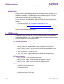
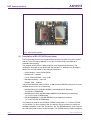
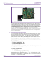
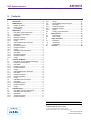
AN10815
SWIM: NXP's basic graphics library for LPC products
Rev. 01 — 1 May 2009
Application note
Document information
Info
Content
Keywords
SWIM, Graphics Library for LPC24xx and LPC32X0, LCD, TFT, STN,
IRD, Phytec, Embedded Artists, Keil MDK, IAR EWARM, Rowley
Crossworks.
Abstract
This document describes example projects created to demonstrate the
LPC SWIM Graphics library. Toolchains used are Keil MDK, IAR EWARM
and Rowley Crossworks. The development platforms were from
Embedded Artists, NXP, and Phytec.
AN10815
NXP Semiconductors
SWIM: NXP's basic graphics library for LPC products
Revision history
Rev
Date
Description
01
20090501
Initial revision
Contact information
For additional information, please visit: http://www.nxp.com
For sales office addresses, please send an email to: [email protected]
AN10815_1
Application note
© NXP B.V. 2009. All rights reserved.
Rev. 01 — 1 May 2009
2 of 15
AN10815
NXP Semiconductors
SWIM: NXP's basic graphics library for LPC products
1. Introduction
Simple Window Interface Manager (SWIM) is a basic graphics library developed for the
NXP LPC products. It can be also be used with LPC controllers that do not have a
dedicated LCD interface. The SWIM graphics library allows developers to quickly and
easily implement a system with basic graphics support.
Project examples for IAR EWARM, KEIL MDK, and Rowley Crossworks toolchains are
provided as part of the package. These projects are directed at the following target
platforms:
• LPC3250 from Phytec: http://www.nxp.com/redirect/phytec.com
• LPC2478 from EA: http://www.nxp.com/redirect/embeddedartists.com
• IRD Platform from NXP: http://www.standardics.nxp.com/support/boards/ird
The example projects demonstrate how to use the library and will help users get familiar
with the library calls quickly and efficiently.
2. SWIM features
The following section describes the main features and functionality of the SWIM library.
In addition, the library code is well commented and an associated API document for the
software calls - SWIM v1.0.pdf – is also available. Some of the main SWIM functions are
briefly summarized in the following subsections.
2.1 Graphic primitives
• swim_put_pixel – places a pixel of specified color at a specified location on the LCD
• swim_put_line – draws a colored line for positions x to y
• swim_put_diamond – draws a diamond shape of specified color and position
• swim_put_box – put box at specified location. Pen color for edges and fill color for
center
• swim_set_pen_color – sets the pen color
• swim_clear_screen – fills the draw area of the display with the selected color
2.2 Image support
• swim_put_image – puts a raw image into a window
• swim_put_scale_image – puts and scales a raw image into a window
• swim_put_invert_image – puts a raw image into a window inverted
2.3 Font support
• Helvetica 10-point proportional font
• 8x16 proportional font
• 8x8 proportional font
• Fixed 5x7 proportional font
• Windows FreeSystem 14x16 Font
AN10815_1
Application note
© NXP B.V. 2009. All rights reserved.
Rev. 01 — 1 May 2009
3 of 15
AN10815
NXP Semiconductors
SWIM: NXP's basic graphics library for LPC products
3. IRD platform
The Industrial Reference Design (IRD) v2.0 is a platform targeted at RTOS based
embedded systems. Designed around a flexible Core and Base printed circuit board
(PCB) concept, it features many of the system functions and wired communications
protocols found in today's embedded applications. The examples provided with this
SWIM library are developed for use with the LPC2478 core board module.
Fig 1. IRD platform
3.1 Description of IRD board setup
The IRD 2.0 platform should come preassembled with the LPC2478 core board installed
and the Toshiba LCD module attached. If not, refer to the IRD User’s Manual to
assemble them properly. There are no jumpers to configure that affect the example code
for this platform.
The IRD 2.0 2478 board has either 8 MB, 16 MB, or 32 MB external SDRAM using a
64 Mbit, 128 Mbit, or 256 Mbit x 32 SDRAM device in U6 respectively:
• MT48LC2M32B2 (64 Mbit SDRAM, 32-bit databus) from Micron (default)
• MT48LC4M32B2 (128 Mbit SDRAM, 32-bit databus) from Micron (option)
• MT48LC8M32B2 (256 Mbit SDRAM, 32-bit databus) from Micron (option)
The supplied example is setup for the 64 Mbit (8 MB) Micron SDRAM configuration.
For other versions of the core board it will be necessary to modify the SDRAM
initialization code in the "ex_sdram.c" file. This SDRAM memory will be used as the LCD
frame buffer memory for this example. The SDRAM memory resides at address:
0xA000 0000 - 0xA07F FFFFF using DYNCS0 (8 MB, 2Mx32)
AN10815_1
Application note
© NXP B.V. 2009. All rights reserved.
Rev. 01 — 1 May 2009
4 of 15
AN10815
NXP Semiconductors
SWIM: NXP's basic graphics library for LPC products
Using the 240x320 16bpp RGB1:5:5:5 mode, the frame buffer uses 150 kB of SDRAM
starting at address 0xA0000000.
The parameters for the Toshiba LCD panel are configured in lcd_params.c; this panel is
configured for operation in 1:5:5:5 mode.
3.2 Rowley project description
3.2.1 Description
Draws color bars and text on the LCD using the SWIM library with LCD in RGB1:5:5:5
mode.
3.2.2 Required hardware
IRD 2.0 2478 Evaluation board w/Toshiba LTA057A347F 5.7" 320x240 LCD module.
3.2.3 Required software
Rowley CrossStudio for ARM v1.5 or newer.
Rowley CrossConnect for ARM or other supported debugger.
3.2.4 Usage
1) Start Rowley CrossStudio for ARM and open the example solution file.
Select File->Open Solution->
Open the following solution: LPC2478_SWIM_Example.hzp
2) Build the solution.
Build->Build Solution
3) Attach your CrossConnect debugger to the IRD 2.0 board and PC, then
connect to it.
Targets->Connect USB CrossConnect for ARM
4) Download the program into flash.
Debug->Start Debugging (F5)
5) Run the program!
Debug->Go (F5)
3.3 IAR EWARM project description
3.3.1 Description
Draws color bars and text on the LCD using the SWIM library with LCD in RGB1:5:5:5
mode.
3.3.2 Required hardware
IRD 2.0 2478 Evaluation board w/Toshiba LTA057A347F 5.7" 320x240 LCD module
3.3.3 Required software
IAR Embedded Workbench for ARM (EWARM) v5.x or newer
3.3.4 Usage
1) Start IAR Embedded Workbench for ARM and open the example workspace space.
File->Open->Workspace...
AN10815_1
Application note
© NXP B.V. 2009. All rights reserved.
Rev. 01 — 1 May 2009
5 of 15
AN10815
NXP Semiconductors
SWIM: NXP's basic graphics library for LPC products
Open the following workspace: 2478_swim_example.eww
2) Build the project.
Project->Rebuild All
3) Attach your JLink JTAG unit to the EA-2478 board and PC.
4) Download the program into flash.
Project->Download and Debug (Ctrl+D)
5) Run the program!
Debug->Go (F5)
3.4 Keil MDK project description
3.4.1 Description
Draws color bars and text on the LCD using the SWIM library with LCD in RGB1:5:5:5
mode.
3.4.2 Required hardware
IRD 2.0 2478 Evaluation board w/Toshiba LTA057A347F 5.7" 320x240 LCD module.
3.4.3 Required software
Keil uVision v3.x or newer. Code should compile on evaluation version.
3.4.4 Usage
1) Start Keil uVision3 for ARM and open the example project file.
Project->Open Project...
Open the following project: ea_lcd.Uv2
2) Build the project.
Project->Build Target
3) Attach your ULink2 JTAG unit to the IRD 2.0 board and PC.
4) Download the program into flash.
Debug->Start/Stop Debug Session (Ctrl+F5)
5) Run the program!
Debug->Run (F5)
4. LPC2478 EA Board
Embedded Artists' LPC2478 OEM Board (mounted on the QVGA OEM Base Board with
touch panel) lets you get up-and-running quickly with NXP's ARM7TDMI LPC24xx
microcontroller series.
The OEM board has SODIMM format and is only 66x48 mm. All processor signals are
available on the 200-pin connector for easy expansion. The board can be used in OEM
applications, as well as for educational purposes, experiments, and prototype projects.
AN10815_1
Application note
© NXP B.V. 2009. All rights reserved.
Rev. 01 — 1 May 2009
6 of 15
AN10815
NXP Semiconductors
SWIM: NXP's basic graphics library for LPC products
Fig 2. EA LPC2478 Platform
4.1 Description of EA LPC2478 board setup
The EA-2478 board should come preassembled with the LPC2478 core board installed
and the Truly LCD module attached. If not, refer to the EA-2478 User’s Manual to
assemble them properly.
The jumpers can be left in the default position when shipped from the factory. The
jumpers on this board are not labeled with the standard “J1” labels but only descriptive
labels. The ones that matter for the example projects are:
• Int/Ext display – set to internal display
• Enable LCD – installed
• 16 bit / 24 bit RGB data – set to 16 bit
• Backlight shutdown – removed
• Enable JTAG – installed
The EA-2478 board has either 32 MB or 16 MB of external SDRAM using a x16 or a x32
SDRAM device in U9 or U13 respectively:
• K4S561632H-UC75 (256 Mbit SDRAM, 16-bit databus) from Samsung
(LPC2478-16 OEM Board)
• K4M563233G-HN75 (256 Mbit Mobile SDRAM, 32-bit databus) from Samsung
(v1.0 of LPC2478-32 OEM Board)
• MT48LC8M32B2B5-7 (256 Mbit SDRAM, 32-bit databus) from Micron
(v1.1a of LPC2478-32 OEM Board)
This example is setup for the x32 Micron SDRAM configuration, v1.1a of the LPC247832 core board. For other versions of the core board it may be necessary to modify the
SDRAM initialization code in the "ex_sdram.c" file. The SDRAM memory will be used as
the LCD frame buffer memory for this example. The SDRAM memory resides at address:
AN10815_1
Application note
© NXP B.V. 2009. All rights reserved.
Rev. 01 — 1 May 2009
7 of 15
AN10815
NXP Semiconductors
SWIM: NXP's basic graphics library for LPC products
• 0xA0000000 - 0xA1FFFFFF using DYNCS0 (32 MB, 8Mx32)
In 240x320 16bpp RGB1:5:5:5 mode, the frame buffer uses 150 kB starting at:
• 0xA0000000 within the SDRAM.
The Truly LCD module on the EA-2478 board contains a complete LCD controller
module with its own frame buffer as well as a hardware touchscreen controller. The
example presented disables the LCD controller and frame buffer on the Truly module and
places the LCD module into a dumb RGB1:5:5:5 mode. The SPI interface to the module
is used to program the module into this mode. The parameters for the Truly LCD panel
are configured in lcd_params.c.
4.2 Rowley project description
4.2.1 Description
Draws color bars on the LCD using the SWIM library with LCD in RGB1:5:5:5 mode.
4.2.2 Required hardware
EA-2478 Evaluation board w/Truly LCD module in RGB1:5:5:5 mode
Rowley CrossConnect for ARM or other supported debugger
4.2.3 Required software
Rowley Crossworks for ARM v1.5 or newer
4.2.4 Usage
1) Start Rowley CrossStudio for ARM and open the example solution file.
Select File->Open Solution
Open the following solution: EAC2478_SWIM_Example.hzp
2) Build the solution.
Build->Build Solution
3) Attach your CrossConnect debugger to the EA-2478 board and PC, then
connect to it.
Targets->Connect USB CrossConnect for ARM
4) Download the program into flash.
Debug->Start Debugging (F5)
5) Run the program!
Debug->Go (F5)
4.3 IAR EWARM project description
4.3.1 Description
Draws color bars on the LCD using the SWIM library with LCD in RGB1:5:5:5 mode.
4.3.2 Required hardware
EA-2478 Evaluation board w/Truly LCD module
4.3.3 Required software
IAR Embedded Workbench for ARM (EWARM) v5.x or newer
AN10815_1
Application note
© NXP B.V. 2009. All rights reserved.
Rev. 01 — 1 May 2009
8 of 15
AN10815
NXP Semiconductors
SWIM: NXP's basic graphics library for LPC products
4.3.4 Usage
1) Start IAR Embedded Workbench for ARM and open the example workspace space.
File->Open->Workspace...
Open the following workspace: ea2478_swim_example.eww
2) Build the project
Project->Rebuild All
3) Attach JLink JTAG unit to the EA-2478 board and PC
4) Download the program into flash
Project->Download and Debug (Ctrl+D)
5) Run the program!
Debug->Go (F5)
4.4 Keil MDK project description
4.4.1 Description
Draws color bars and text on the LCD using the SWIM library with LCD in RGB1:5:5:5
mode.
4.4.2 Required hardware
EA-2478 Evaluation board w/Truly LCD module.
4.4.3 Required software
Keil uVision v3.x or newer. Tested with Evaluation version of MDK.
4.4.4 Usage
1) Start Keil uVision3 for ARM and open the example project file.
Project->Open Project...
Open the following project: ea_lcd.Uv2
2) Build the project.
Project->Build Target
3) Attach ULink2 JTAG unit to the EA-2478 board and PC .
4) Download the program into flash.
Debug->Start/Stop Debug Session (Ctrl+F5)
5) Run the program!
Debug->Run (F5)
5. LPC3250 Phytec
The LPC3250 Phytec system is made up from three boards: the phyCOREARM9/LPC3250 System on Module (PCM-040), the phyCORE-ARM9/LPC3250 Carrier
Board (PCM-967), and a optional add-on LCD - Hitachi 3.5" QVGA TFT-LCD with
integrated touch on adapter board (KLCD-011). The complete system is shown in Fig 3.
AN10815_1
Application note
© NXP B.V. 2009. All rights reserved.
Rev. 01 — 1 May 2009
9 of 15
AN10815
NXP Semiconductors
SWIM: NXP's basic graphics library for LPC products
Fig 3. Phytec LPC3250 Platform
The phyCORE-LPC3250 module is populated with the NXP LPC3250. State-of-the-art
power management, Vector Floating Point Unit (VFP), and rich peripherals such as USB
OTG, Ethernet, and integrated LCD controller make this device the ideal candidate for
embedded applications requiring high performance and low power consumption. The onboard MMU supports major operating systems, including Linux and Windows Embedded
CE. Other chip-level features include 7 UARTs, SPI, I2C, a real-time clock with a
separate power domain, and NAND Flash and DDR memory controllers. These features
make the devices particularly suitable for automotive and industrial control applications
as well as medical systems.
5.1 Description of Phytec board setup
The LPC3250 Phytec is shipped with a preinstalled bootloader called the stage 1 loader
(S1L). It is assumed that this is present on the board. The S1L first initializes the board
with the code from the phy3250_startup_entry.s and phy3250_startup.c files before
starting the monitor program. Without this initialization the colorbar example will not run.
Be sure to configure your system defines in phy3250_board.h to match your hardware
revisions. Failure to properly set these defines to the correct value may prevent the code
from working correctly.
The possible define values are below:
• PHY3250_CARRIERBOARD_1305_X
• PHY3250_MODULEBOARD_1304_X
• PHY3250_LCD_1307_X
LCD modules have a board number of 1307.x, where x = 0 or 1. The change between .0
and .1 LCD module is detailed below:
LCD module revision differences:
.0
initial board
.1
Active HIGH backlight signal, different wiring
Because of differences in the connector wiring of ‘.0’ and ’.1’ LCD modules, the ‘.0’ LCD
modules should only be used with ‘.0’ carrier boards, while ‘.1’ LCD modules should only
be used with ’.2’ or greater carrier boards.
AN10815_1
Application note
© NXP B.V. 2009. All rights reserved.
Rev. 01 — 1 May 2009
10 of 15
AN10815
NXP Semiconductors
SWIM: NXP's basic graphics library for LPC products
Carrier boards have a revision number of 1305.x, where x = 0 to 3. The changes
between the boards module are shown below:
Carrier board revision differences:
.0/.1
Initial board
.2/.3
USB peripheral VBUS routed to USB_VBUS signal
.2/.3
GPI4 used to VBUS detection for USB peripheral
.2/.3
USB_ADR/SW used to control USB_ host power
Module boards have a revision number of 1304.x, where x = 0 to 1. The changes
between the module boards module are shown below:
Module board revision differences:
.0
Initial board
.1
USB ISP1301 I2C address changed from 0x2C to 0x2D
For correct jumper settings please refer to the PHYTEC phyCORE-LPC3250 System on
Module and Carrier Board Hardware Manual.
The phyCORE-LPC3250 board comes preconfigured with 64 MB of 133 MHz SDR
SDRAM configured for 32-bit access using two 16-bit wide RAM chips at U10 and U11.
The LPC3250 is capable of addressing a single RAM bank located at memory address
0x8000 0000 and extending to 0x9FFF FFFF via the /DYCS0 signal.
The LCD is a Hitachi TX09D71VM1CCA. In 240x320 16bpp RGB565 mode the frame
buffer uses 150kB starting at: 0x8000 0000 within the SDRAM. The parameters for the
Hitachi LCD panel are configured in lpc_lcd_params.c
5.2 Keil MDK project description
5.2.1 Description
Draws color bars and text on the LCD using the SWIM library with LCD in RGB1:5:6:5
mode.
5.2.2 Required hardware
LPC3250 Phytec board with LCD.
5.2.3 Required software
Keil uVision v3.x or newer. Tested with Evaluation version of MDK.
5.2.4 Usage
The code is setup to execute from IRAM (Debug version) of the LPC3250.
1) Start Keil uVision3 for ARM and open the example project file
Project->Open Project...
2) Build the project
Project->Build Target
3) Attach ULink2 JTAG unit to the Phytec board and PC
4) Download the program
Debug->Start/Stop Debug Session (Ctrl+F5)
AN10815_1
Application note
© NXP B.V. 2009. All rights reserved.
Rev. 01 — 1 May 2009
11 of 15
AN10815
NXP Semiconductors
SWIM: NXP's basic graphics library for LPC products
5) Run the program!
Debug->Run (F5)
For instructions on how to load the code into NAND Flash (Release version) please refer
to the documents in the LPC3250 Common Driver Library package which can be
downloaded at www.nxp.com/microcontrollers.
Keil also provides a NAND Flash bootloader which can be used to download the code in
to NAND flash. Refer to the Keil documentation/examples on how to save and execute
the code from NAND flash.
5.3 IAR EWARM project description
5.3.1 Description
Draws color bars and text on the LCD using the SWIM library with LCD in RGB1:5:6:5
mode.
5.3.2 Required hardware
LPC3250 Phytec board with LCD.
5.3.3 Required software
The project was developed using IAR Embedded Workbench ARM v5.x or newer. The
IAR Evaluation version will also work.
5.3.4 Usage
The code is setup to execute from IRAM (Debug version) of the LPC3250.
1) Start EWARM and open the example project file.
Project->Open Project.
2) Build the project.
Project->Build Target
3) Attach JLINK JTAG unit to the Phytec board and PC.
4) Download the program.
Debug->Start/Stop Debug Session (Ctrl+F5)
5) Run the program!
Debug->Run (F5)
For instructions on how to load the code into NAND Flash (Release version) please refer
to the documents in the LPC3250 Common Driver Library package which can be
downloaded at www.nxp.com/microcontrollers.
IAR also provides a NAND Flash bootloader which can be used to download the code in
to NAND flash. Refer to the IAR documentation/examples on how to save and execute
the code from NAND flash.
5.4 Rowley project description
Currently Rowley Crosswork does not support the NXP LPC3250 microcontroller.
AN10815_1
Application note
© NXP B.V. 2009. All rights reserved.
Rev. 01 — 1 May 2009
12 of 15
AN10815
NXP Semiconductors
SWIM: NXP's basic graphics library for LPC products
6. Miscellaneous
6.1 RGB setting
The SWIM RGB format will need to be adapted depending on the format supported by
the LCD and the manner in which the LCD is connected to the LPC controller.
For the Phytec board, the LCD uses RGB565 while the EA and IRD systems use
RGB555.
In the file “lpc_colors.h” set the RGB for the particular format as shown below:
For Phytec LPC3250 Board:
#define COLORS_DEF 16
/* 16-bit 565 color mode */
For EA LPC2478 and IRD boards:
#define COLORS_DEF 15
/* 15-bit 555 color mode */
The SWIM library will can also be used to manipulate and display Bitmaps.
6.2 Demo output
The snapshot in Fig 4 shows the resulting LCD panel look and feel when the code is run
on the different platforms. The image in this case is taken from the EA LPC2478 Board.
Fig 4. Phytec LPC3250 platform
AN10815_1
Application note
© NXP B.V. 2009. All rights reserved.
Rev. 01 — 1 May 2009
13 of 15
AN10815
NXP Semiconductors
SWIM: NXP's basic graphics library for LPC products
7. Legal information
7.1 Definitions
Draft — The document is a draft version only. The content is still under
internal review and subject to formal approval, which may result in
modifications or additions. NXP Semiconductors does not give any
representations or warranties as to the accuracy or completeness of
information included herein and shall have no liability for the consequences
of use of such information.
7.2 Disclaimers
General — Information in this document is believed to be accurate and
reliable. However, NXP Semiconductors does not give any representations
or warranties, expressed or implied, as to the accuracy or completeness of
such information and shall have no liability for the consequences of use of
such information.
Right to make changes — NXP Semiconductors reserves the right to make
changes to information published in this document, including without
limitation specifications and product descriptions, at any time and without
notice. This document supersedes and replaces all information supplied prior
to the publication hereof.
Suitability for use — NXP Semiconductors products are not designed,
authorized or warranted to be suitable for use in medical, military, aircraft,
space or life support equipment, nor in applications where failure or
malfunction of a NXP Semiconductors product can reasonably be expected
to result in personal injury, death or severe property or environmental
damage. NXP Semiconductors accepts no liability for inclusion and/or use of
NXP Semiconductors products in such equipment or applications and
therefore such inclusion and/or use is for the customer’s own risk.
Applications — Applications that are described herein for any of these
products are for illustrative purposes only. NXP Semiconductors makes no
representation or warranty that such applications will be suitable for the
specified use without further testing or modification.
Export control — This document as well as the item(s) described herein
may be subject to export control regulations. Export might require a prior
authorization from national authorities.
7.3 Trademarks
Notice: All referenced brands, product names, service names and
trademarks are property of their respective owners.
AN10815_1
Application note
© NXP B.V. 2009. All rights reserved.
Rev. 01 — 1 May 2009
14 of 15
AN10815
NXP Semiconductors
SWIM: NXP's basic graphics library for LPC products
8. Contents
1.
2.
2.1
2.2
2.3
3.
3.1
3.2
3.2.1
3.2.2
3.2.3
3.2.4
3.3
3.3.1
3.3.2
3.3.3
3.3.4
3.4
3.4.1
3.4.2
3.4.3
3.4.4
4.
4.1
4.2
4.2.1
4.2.2
4.2.3
4.2.4
4.3
4.3.1
4.3.2
4.3.3
4.3.4
4.4
4.4.1
4.4.2
4.4.3
4.4.4
5.
5.1
5.2
5.2.1
5.2.2
5.2.3
Introduction .........................................................3
SWIM features......................................................3
Graphic primitives ..............................................3
Image support ....................................................3
Font support .......................................................3
IRD platform.........................................................4
Description of IRD board setup ..........................4
Rowley project description .................................5
Description .........................................................5
Required hardware.............................................5
Required software ..............................................5
Usage.................................................................5
IAR EWARM project description ........................5
Description .........................................................5
Required hardware.............................................5
Required software ..............................................5
Usage.................................................................5
Keil MDK project description ..............................6
Description .........................................................6
Required hardware.............................................6
Required software ..............................................6
Usage.................................................................6
LPC2478 EA Board..............................................6
Description of EA LPC2478 board setup............7
Rowley project description .................................8
Description .........................................................8
Required hardware.............................................8
Required software ..............................................8
Usage.................................................................8
IAR EWARM project description ........................8
Description .........................................................8
Required hardware.............................................8
Required software ..............................................8
Usage.................................................................9
Keil MDK project description ..............................9
Description .........................................................9
Required hardware.............................................9
Required software ..............................................9
Usage.................................................................9
LPC3250 Phytec ..................................................9
Description of Phytec board setup ...................10
Keil MDK project description ............................11
Description .......................................................11
Required hardware...........................................11
Required software ............................................11
5.2.4
5.3
5.3.1
5.3.2
5.3.3
5.3.4
5.4
6.
6.1
6.2
7.
7.1
7.2
7.3
8.
Usage ...............................................................11
IAR EWARM project description.......................12
Description .......................................................12
Required hardware...........................................12
Required software ............................................12
Usage ...............................................................12
Rowley project description................................12
Miscellaneous ....................................................13
RGB setting ......................................................13
Demo output.....................................................13
Legal information ..............................................14
Definitions.........................................................14
Disclaimers.......................................................14
Trademarks ......................................................14
Contents .............................................................15
Please be aware that important notices concerning this document and the product(s)
described herein, have been included in the section 'Legal information'.
© NXP B.V. 2009. All rights reserved.
For more information, please visit: http://www.nxp.com
For sales office addresses, email to: [email protected]
Date of release: 1 May 2009
Document identifier: AN10815_1