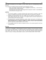
1
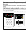
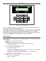
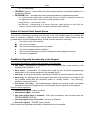
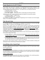
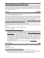
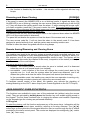
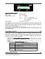
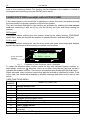
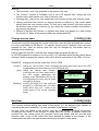
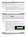
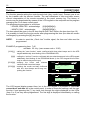
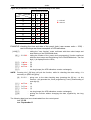
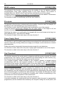
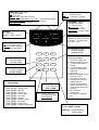
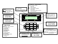
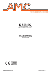
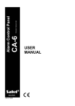
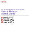
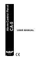
CA-5 Alarm Control Panel GDAŃSK POLAND ca5u_e 06/04 USER MANUAL WARNING In order to avoid any operational problems with the control panel, it is recommended that you become familiar with this manual before you start using the equipment. Making any construction changes or unauthorized repairs is prohibited. This applies, in particular, to modification of assemblies and components. Maintenance or repair operations should be performed by authorized personnel (i.e. the installer or factory service). Telephone terminals of the panel should be connected to PSTN lines only. Connecting to ISDN lines may lead to damage of the equipment. In case of upgrading the PSTN line to ISDN, system owner should contact the installer. Pay special attention if the telephone line used by the control panel is frequently busy and/or failures are reported concerning the line and/or monitoring. Report such situations to the alarm system installer immediately. CAUTION! The alarm system is fitted with a battery. After expiry of its service, the battery must not be thrown away, but disposed of as required by the existing regulations (European Union Directives 91/157/EEC and 93/86/EEC). Latest EC declaration of conformity and product approval certificates can be downloaded from our Web site www.satel.pl Definitions of some technical terms as used in this manual: • Service mode – the control panel condition which permits calling of the service functions and programming of the security system parameters. • User function mode – the control panel condition which permits performing the user code protected functions (which are described herein). CONTENTS TECHNICAL RELIABILITY OF THE SECURITY SYSTEM ................................................ 2 ALARM SYSTEM OPERATING COSTS ............................................................................ 2 GENERAL FEATURES....................................................................................................... 2 OPERATION ....................................................................................................................... 3 LED Functions ..............................................................................................................................4 Status of Control Panel Armed Zones ...........................................................................................5 Conditions Signaled Acoustically in the Keypad ............................................................................5 Events Signaled on the OUT1 Output ...........................................................................................6 User Access Codes.......................................................................................................................6 Armed Mode of the Control Panel .................................................................................................6 FULL ARMED MODE ......................................................................................................................................6 SILENT ARMED MODE ..................................................................................................................................6 PARTIAL ARMED MODE WITH NO EXIT FROM THE SITE .........................................................................7 Arming [CODE][#] ....................................................................................................................7 Quick Arming [0][#].....................................................................................................................7 Disarming and Alarm Clearing [CODE][#]...................................................................................8 Remote Arming/Disarming and Clearing Alarm .............................................................................8 „HOLD DOWN” USER FUNCTIONS.................................................................................. 8 Alarm Memory Review [5] .........................................................................................................9 Trouble Memory Review [6].......................................................................................................9 Current Trouble Check-out [7] .................................................................................................10 Switching the Chime On/Off [8] ................................................................................................11 Fire Alarm [*] ............................................................................................................................11 Auxiliary Alarm [0] ....................................................................................................................11 Panic Alarm [#] ........................................................................................................................11 USER FUNCTIONS accessible with ACCESS CODE .................................................... 12 LED keypad ...................................................................................................................................................12 LCD keypad...................................................................................................................................................12 Change access code [CODE][*][1][#] .......................................................................................13 Add User [CODE][*][2][#] ........................................................................................................13 Erase User [CODE][*][3][#].....................................................................................................14 Bypass zones [CODE][*][4][#] ..................................................................................................14 Arm Silent [CODE][*][5][#] ........................................................................................................15 Set time [CODE][*][6][#] ...........................................................................................................16 MONO outputs [CODE][*][7][#].................................................................................................18 BI outputs [CODE][*][8][#] ........................................................................................................18 Power Supply Reset [CODE][*][9][#] ........................................................................................18 Start Download [CODE][*][0][#] ................................................................................................18 Events.........................................................................................................................................19 TECHNICAL RELIABILITY OF THE SECURITY SYSTEM The security system is built of technical devices, the reliability of which is vital for effectiveness of the site protection. The security system elements are exposed to a variety of outside factors, including the weather conditions (outside signaling devices), lightning (overhead telephone lines, power lines, outside signaling devices), mechanical damage (keypads, detectors. etc.). Maintaining a high level of the security system reliability is only possible by current control of the functioning of particular devices. The control panel is equipped with a number of safeguards and auto diagnostic functions intended for testing the system reliability. The control panel signals trouble detection by switching on the TROUBLE LED on the keypad. Such a situation requires an immediate response and, if necessary, consultation with the installer. It is necessary to periodically test the security system functioning. Make sure that the control panel reacts to violation of individual detectors, that their field of vision is not blocked, that there is a reaction to the opening of protected doors and windows, and that the functioning of signaling devices and telephone monitoring is correct. The installer gives specific instructions on how the system should be controlled. Periodic commissioning of the installer's maintenance service is recommended. The user, in his own interest, should predict unexpected alarm conditions and plan adequate procedures. It is vital to be able to verify the alarm, to determine its source based on the keypad information, and to take appropriate measures, e.g. organizing evacuation. ALARM SYSTEM OPERATING COSTS The main task of the control panel is signaling and efficient reporting of alarm situations and, in the case of the monitoring function, keeping the monitoring station informed about the protected facility status. Performance of these functions is to a large extent based on the use of a telephone line, which entails generating certain costs. Generally, the level of costs incurred by the alarm system owner depends on the amount of information the control panel has to transfer to the monitoring station. A failure of the telephone links, as well as incorrect programming of the control panel, may to a large degree increase these costs. Such a situation is usually related to an excessive number of connections made. The installer can adjust functioning of the alarm system to the specific conditions and kind of the protected site, however it is the user who should decide if his or her priority is transferring information at any price, or, if some technical problems occur, the control panel is allowed to skip some events, the reception of which has not been confirmed by the monitoring station. GENERAL FEATURES The CA-5 alarm control panel is an advanced, microprocessor base device designed for burglary and assault alarm systems. It is characterized by a simplicity of operation, legibility of information for the user, and a high operational reliability. It has been fitted with a telephone communicator (dialer) which enables the security system to operate together with a monitoring station. The control panel is intended for a variety of sites, including apartments, detached houses, warehouses, stores, kiosks, etc. CA-5 3 SATEL OPERATION This manual contains description of operating the CA-5 alarm control panel by means of the LED-M keypad. Basic operation of the security system comes down to arming and disarming the system (supervision), and to adequate reaction to the information the control panel may signal on the keypad. By means of the control panel keypad, it is possible to trigger special alarms (PANIC, FIRE, HELP), to bypass the incoming lines, to establish communication with the service computer, and also to control external electrical equipment, such as: electromagnetic lock, fan, lighting, etc. The keypad provides information on the security system status by means of 10 light emitting diodes (LED) and audible signals. The LCD keypad provides information on the alarm system status by means of a liquidcrystal display (2x16 characters), 3 light emitting diodes (LEDs), as well as audible signals. ALARM 1 2 POWER 3 TROUBLE ARMED 4 5 PROGRAM alarm armed power program 1 2 3 4 zones 2 trouble 3 4 5 6 7 8 9 ¾ 1 5 0 # 1 abc 2 def 3 ghi 4 jkl 5 mno 6 pqrs 7 tuv 8 wxyz 9 ¾ 0 CA-5 KLED-S keypad CA-5 KLED-M keypad Figure 1. LED keypads. # 4 User Manual alarm ALARM CONTROL PANEL CA-5 LCD 8 Jul, 13:26:41 ..... armed trouble 1 abc 2 def 4 jkl 5 mno 6 ▲ tuv 8 wxyz 9 ▼ 0 # ◄ ghi ► pqrs 7 À 3 Figure 2. CA-5 LCD keypad There are available two version of LCD keypads (CA-5 KLCD-L and CA-5 KLCD-S) that differ in the dimension and the size of display. The keypad and the display backlight illumination can be permanent or switched on automatically by pressing a key, or, alternatively, by violation of any control panel zone when armed – the mode of backlight operation should be determined by the installer. The number key letters help the user memorize a code by associating it with a particular word (e.g. the „[5][6][2][7][2]” code corresponds to the word „KOBRA”). LED Functions Some of the LEDs are mounted only in the LED keypads type – their tasks are performed by LCD display. • ALARM (red) – signals an alarm condition. • ARMED (green) – indicates the system status: − blinking (with the ALARM diode off) - countdown of the exit delay time, − on - the zone is armed. • 1÷5 – the status of control panel armed zones: − − − − − − off - the zone is free (not violated) on - the zone is violated on with short extinguishing every 2 seconds - the zone anti-tampering circuit is violated fast blinking - the zone caused an alarm condition blinking every 2 seconds - the zone anti-tampering circuit has caused an alarm slow blinking - the zone is bypassed • POWER (green) – indicates the control panel power supply status: − on - power supply and battery OK − blinking - low battery CA-5 SATEL 5 − off - no mains power • TROUBLE (yellow) – blinks when the control panel detects a technical problem or a monitoring problem. • PROGRAM (red) – indicates the control panel operation in programming mode: − on – service mode (additionally, a short beep every 3 seconds) – pressing successively the [0][#] keys will cause return to the normal operation mode − slowly blinking – user function mode − fast blinking – programming of a function has been called (service or user one); the alarm or trouble review function has been activated (HOLD DOWN). Status of Control Panel Armed Zones The first five characters (counting from the left) in the LCD display lower line indicate the state of detectors attached to the control panel armed zones. Stated below are the symbols which may be displayed there, as well as their respective meaning: - the zone is free (not violated) ¦ - the zone is violated - the zone anti-tampering circuit is violated a - the zone caused an alarm condition s - the zone anti-tampering circuit has caused an alarm (tamper memory) b - the zone is bypassed Conditions Signaled Acoustically in the Keypad The signals generated to confirm the operation on the keypad: • one short – confirmation of pressing a key; activation of the review function in the keypad (HOLD DOWN: 5, 6, 7) • three short - confirmation of entering the mode of user functions programming; deactivation of the chime signaling in the keypad (key 8), • two long - a wrong access code, canceling a function or incorrect data for a function, • three long - an attempt to arm the system when the control panel is not ready for the job (violated zones with the activated option of „arming control” - see „Arming”), refusal to enter the function, • four short, one long – arming/disarming, entering the service mode, successful completion of function programming, activating the chime signaling in the keypad. System events signaling: • continuous signal – alarm condition, • intermittent signal - fire alarm, • one short signal every 3 seconds - entry time countdown; service mode (with the PROGRAMMING LED on), • one long signal every 3 seconds - exit time countdown, • five short signals - "CHIME" zone violated. Which events are signaled acoustically is determined by the installer. 6 User Manual Events Signaled on the OUT1 Output The installer may activate the signaling of arming/disarming and alarm clearing on the OUT1 output. If this output controls the siren operation, it will generate short sounds (similarly as with the car alarm systems). The signals have the following meanings : • one short sound – arming, • two short sounds – disarming, • four short sounds – clearing the alarm or disarming and clearing the alarm. Additionally, the OUT1 output signals the typical situations for the security system: • continuous signal – burglary alarm, • intermittent signal 1s/1s – fire alarm. The installer may select an identical way of signaling for the fire alarm as for the burglary alarm (i.e. the continuous signal). User Access Codes For everyday operation of the system it is necessary to know the user access code (the access code is a sequence of 4 to 8 digits within the range of 0-9). Entering of the access code in the control panel consists in pressing the corresponding keys on the keypad according to the order of the code digits and finishing the full sequence with the [#] or [*] keys (depending on the intended purpose). The control panel comes with the factory-set master user access code: 1234 and the service code: 12345. Using the master user code it is possible to program 5 additional user access codes, or to delete them if they were programmed before. The installer can assign specific authority levels to some of the access codes to distinguish them from the other user codes: • Access code No. 4 – action under duress (disarming by means of this code results in sending a special code to the monitoring station). This type of access code cannot be changed with user function 1; • Access code No. 5 – permits disarming only when the same access code was used for arming the system, thus making it possible to control (block) access to the site for the user who has such an access code at his disposal. The service code provides access to some of the user functions (besides creating and deleting the users, and arming or disarming the system). Armed Mode of the Control Panel In order to adjust the security system to various situations, the CA-5 control panel offers several armed modes: FULL ARMED MODE The operating mode when detectors connected to the control panel control the protected site and violation of the protected areas is signaled by the control panel with any available means (monitoring, signaling devices, keypad). SILENT ARMED MODE The supervision mode during which the alarms are transmitted to the monitoring station, signaled in the keypad, and on the „Keypad alarm” type of output. CA-5 SATEL 7 PARTIAL ARMED MODE WITH NO EXIT FROM THE SITE The supervision mode with automatic bypassing of the zones (detectors) assigned by the installer. If, after arming the system, the user has not left the site and has not violated the entry/exit monitoring line during the exit time countdown, the selected zones of the control panel will be automatically bypassed, and activation of the detectors connected to those zones will trigger no alarm. Arming [CODE][#] The arming is only possible when the system is signaling no alarm and is not in the armed mode: the ALARM and ARMED LEDs are off. In order to arm the system, enter the user access code and confirm it with the [#] key. If you made a mistake when entering the access code, press the [*] key and re-enter the code. The access codes should be entered very carefully. Three consecutive mistakes may trigger the alarm recorded in the events log as the „3 wrong codes alarm”. If the code is entered correctly and arming is possible, the control panel will confirm the entry with four short beeps followed by a long one and will get armed. In case the installer has pre-programmed the „exit delay time”, the ARMED LED will start blinking to indicate beginning of that time countdown, and arming will take place when the countdown is over. The LCD keypad will display information about exit time delay. The installer determines the length of the exit time and the way the audible signaling works. EXAMPLE: Arming with the user access code: 39763. press in turn: [39763] [#] The control panel may fail to arm the system if: • the panel is not ready for arming the system: there are zones indicated by the installer which must not be violated while the system is being armed („arming control” option) and one of them is being violated – the panel signals this state with three long beeps. In such a situation, you should wait until all the zones are ready (in the LED keypad the LEDs 1÷5 will go out; in the LCD keypad – symbols of zone violation) and then arm the system again (enter the access code). If one of the zones remains all the time violated (in the LED keypad one of the LEDs 1÷5 is always on, in the LCD keypad the symbol of zone violation is displayed - it may be caused e.g. by the detector failure), the armed mode can be activated after bypassing the given zone (using the function 4); • the access code is incorrect – this situation is signaled with two long beeps. Quick Arming [0][#] Quick arming without using any access code is possible by consecutive pressing of two keypad keys: EXAMPLE:[0][#] - arming The control panel cannot arm the system when: • an alarm condition is signaled by the panel (the ALARM LED is blinking); • the panel is not ready to arm the system - which is signaled by the panel with three long beeps (see description in the previous paragraph of this manual); 8 User Manual • the function is disabled by the installer – this situation will be signaled with two long beeps. Disarming and Alarm Clearing [CODE][#] If the panel is armed (the ARMED LED is on or blinking) and/or it signals an alarm (the ALARM LED is on or blinking), entering the user access code and confirming it with the [#] or [*] key will disarm the system and/or clear the alarm. If, while entering the access code, you make a mistake, press the [*] key and re-enter the code. The control panel will confirm acceptance of the command by four short beeps and a long one, and by extinguishing the ARMED LED and/or ALARM LED (if it was on) . The service code can only clear the tamper alarm or the keyboard alarm when the ARMED LED is off (the control panel is disarmed). The panel will not disarm the system or clear the alarm if the access code is wrong. The user access code No. 5 will not clear the alarm in the armed mode if it has been assigned a special authority level, and the system was armed by another user. Refusal to clear the alarm is signaled with three long beeps. Remote Arming/Disarming and Clearing Alarm The installer may install in the security system a special remotely controlled radio line, or a special button, designed for quick arming/disarming of the system or clearing of alarm. For this purpose, one of the control panel programmable zones is used. The system will be always armed in this mode (by violation of the zone), irrespective of the status (violation) of the other zones of the control panel. The zone can work in two modes: • bistable - the control panel is armed when the zone is violated, and it is disarmed when the zone is in its normal mode (not violated), • monostable – each violation of the zone will change the control panel state to the opposite one (i.e. it will arm the system when the panel was disarmed, and it will disarm the system and clear the alarm if the panel was armed (and alarming). In the monostable mode, the installer may restrict the zone operation to arming only, while disarming and alarm clearing will require the user access code. To facilitate remote control of the panel, the installer may activate the signaling of arming/disarming on the OUT1 alarm output (see: Events Signaled on the OUT1 Output). „HOLD DOWN” USER FUNCTIONS The functions are available to every user of the protected site (without using the access code). They are activated by holding down the function key until audible signal sounds in the keypad. The first three functions refer to viewing the alarms and troubles. Depending on the keypads type the viewing are performed differently. LCD keypad To start the viewing, call the function and press any of the arrow keys –information will be display on the most recent alarm condition, referring to function selected. The ([S],[T]) arrow keys on the right side of the keypad allow the user to scroll through the list of events provided by the alarm control panel. The events are displayed chronologically ([S] - earlier ones, [T] - later ones). CA-5 9 SATEL alarm ALARM CONTROL PANEL CA-5 LCD 04.07 14:01 zo.5 Tamper alarm armed Figure 2. An event description contains: date time of event source code (if possible) name of event trouble Event description - example. - day and month - hour and minutes - kpd. keypad - zo.n, n=1,2,..,5 - zone number, - us.n, n=1,2,..,5 - ordinary user number n=6 - master user n=7 - service - description in words The ([W],[X]) arrow keys on the left side of the keypad make it possible to display the user name (default one or entered into the control panel memory by the installer using the DLOAD10 computer program). Pressing the same key again will restore the previous mode of event information display. Pressing the [*] key terminates the viewing function. The method of reading information from the LED keypad is described together with particular functions. Alarm Memory Review [5] Holding down the key (until a single beep is heard) will display information on the most recent alarm condition. The PROGRAM LED will be blinking, and the LEDs 1-5 will indicate the cause of the alarm. Pressing any key (except for the [*] key, which gives you the option to quit the memory log review immediately) displays the previous alarm conditions, up to the earliest item recorded: • zone alarms: one of the LEDs 1 to 5 is always lit up (burglary, panic, fire, tamper, and other alarms, depending on how the zone functions have been set up by the installer), • keypad alarms: one of the LEDs is off, and the other LEDs 1 to 5 are on, the meaning of the extinguished diode being as follows: LED No ALARM DESCRIPTION 1 2 3 4 Fire alarm, keypad Panic alarm, keypad Auxiliary alarm, keypad 3 wrong access codes alarm Keypad tamper alarm (short-circuiting of bus wires, cutting off of keypad) 5 Trouble Memory Review [6] This function allows the panel user to review the detailed information on the system trouble conditions from the panel memory log. 10 User Manual On depressing and holding down the key (until you hear a single beep), the PROGRAM LED will start blinking, and the LEDs from 1 to 5 will indicate the type of trouble according to the list contained in the description of the CURRENT TROUBLE CHECK-OUT function. The list of detectable troubles consists of two sets of five items each. Troubles relating to the first set are indicated by the number of a lit up LED, whereas troubles relating to the second set are indicated by the number of an extinguished LED (one of five). The previous (earlier) troubles are available for readout by consecutively pressing any key of the keypad, except for the [*] key which cancels the trouble memory review function. Current Trouble Check-out [7] When the control panel signals a trouble detection (the TROUBLE LED is blinking), holding down the key (until you hear a single beep) will activate the Current Trouble Check-out Function. On activating the function, the PROGRAM LED will start blinking, and the LEDs 1 to 5 will indicate any possible troubles from the first set (list of troubles as per the table). Pressing any key (except for the [*] key) will change the set of displayed troubles to the other one, which will be signaled by two short beeps. Consecutive pressing of any key will display information, alternately, on the first set of troubles and on the second one. Pressing the [*] key will quit the function. The meaning of the LEDs is as follows: LED No. 1 2 3 4 5 FIRST SET OF TROUBLES 230V AC power supply loss Battery trouble (or F1 fuse) OUT1 output trouble (F2 fuse) Power supply outputs trouble (F3 fuse) Clock loss SECOND SET OF TROUBLES 1 2 3 4 5 NOTE: No voltage on telephone line Problem with access to settings memory Wrong communication codes (connections computer blocked for 30 minutes by the panel) Monitoring trouble Dialing error from During the trouble memory review, the extinguished LED No. 3 (a second set trouble) means „Unsuccessful DWNL (downloading)”. The meaning described in the table refers to the current trouble check-out only. DESCRIPTION OF SOME TROUBLE SIGNALING CAUSES 230V AC power supply loss - the control panel is fitted with a backup power supply to enable a limited time operation without the mains supply; if the AC loss is indicated despite the electrical installation being OK, you should call the service. Battery trouble - means that the battery voltage is too low (lower than 12V under load). This condition may hold for several hours after AC supply loss (or after connecting a discharged battery). The battery charging time depends on its capacitance (the battery is charged with direct current of approx. 350mA, the time necessary for testing the battery status is about 12 minutes). This signaling may also indicate blowing of the F1 fuse. OUT1 output trouble - no load (e.g.: the siren wires cut off, the F2 fuse blown) or overload (installation short-circuiting) – usually requires intervention of the service personnel. CA-5 SATEL 11 Power supply outputs trouble - information on the installation fault (F3 fuse), requires intervention of the service personnel (it can be only displayed during the trouble memory review). Clock loss - occurs on disconnecting the power supply and restarting the control panel; the clock and date should be set with the user function 6. No voltage on telephone line - means cut-off of the telephone line; it may be also caused by lifting the handset of the telephone connected to the same line for longer than the time specified by the installer. Problems with access to settings memory – may occur when the RESET pins on the control panel main board are shorted. If the pins are open, and connecting the power off and on does not clear the trouble signaling, intervention of the service personnel is necessary. Wrong communication codes – means that during three consecutive communication sessions with the computer the control panel hanged up after reading three times a wrong communication code – in such a case, the panel suspends communication with the computer for 30 minutes (upon answering a call it sends to the computer a message that the connection capability is disabled and „hangs up”). Monitoring trouble - this message indicates multiple occupancy of the line, when the monitoring station does not lift the handset, does not send the invitation signal, or the confirmation signal after receiving the codes. If this signaling persists, the monitoring is ineffective and requires intervention of the service personnel or the technicians from monitoring station. Dialing error - information on the cause of an unsuccessful telephone connection (lack of the dialing tone after the handset is lifted, or presence of an intermittent signal instead of the continuous one). The signaling of trouble will remain on until next successful telephone connection. Switching the Chime On/Off [8] This function (holding down the key) makes it possible to switch on/off the chime signal (signaling the violation of selected zones when the control panel is disarmed) from the keypad. Three short beeps in the keypad confirm switching off the chime signaling function, whereas four short beeps and a long one mean that the signaling is on. The installer specifies which zones will generate the chime signal. Fire Alarm [* ] This function makes it possible to trigger the fire alarm from the keypad. The control panel activates signaling on the OUT1 output in the keypad and sends an appropriate code to the monitoring station. The function can be disabled by the installer. Auxiliary Alarm [0] The meaning of this alarm is specified depending on the needs. The function may transmit information on the auxiliary alarm to the monitoring station (it may be, for example, a call for medical assistance, as it was adopted in the Contact ID monitoring format). The function may be disabled by the installer. Panic Alarm [#] This function makes it possible to trigger the panic alarm from the keypad. The control panel activates signaling on the OUT1 output in the keypad and sends an appropriate 12 User Manual code to the monitoring station. The function can be disabled by the installer or limited to the keypad and monitoring only (the SILENT panic alarm). USER FUNCTIONS accessible with ACCESS CODE If the control panel is not armed and is signaling no alarm, the users can access several functions useful in everyday operation of the security system. The user functions described in this section are activated by entering the user access code and confirming it with the [*] key (not the [#] key as is the case when arming the system). LED keypad The panel confirms entering the user function mode by the slowly blinking „PROGRAM” diode. Next , press the key with the number of selected function and then the [#] key. LCD keypad The panel confirms entering the user functions mode with three short beeps and displays the two first names out of the currently accessible user functions. alarm ALARM CONTROL PANEL CA-5 LCD ´ 1.Change cursor of function selection code 2.Add user armed trouble Fig. 3 Fragment of user functions menu - example. To reach the required menu function, press the key with selected function number, or, alternatively, move the „´” selection cursor up or down using the [S], [T] keys so that it indicates the suitable function. The function is activated upon pressing the [#] or [X] keys. When activated, some functions require that data be entered or selection be made; if this is the case, the control panel displays a suitable message and waits for the user to take action. USER FUNCTIONS MENU: FUNCTION NUMBER 1 2 3 4 5 6 7 8 9 0 NAME OF FUNCTION Change access code Add user (enters new user code) Erase user (deletes current user code) Bypass zones Arm silent (activates silent armed mode) Set time (programs panel clock) MONO outputs (MONO switch on) BI outputs (BI switch status on/off) Power supply RESET Start DWNL (starts panel programming by the phone from service computer) Events (only in LCD keypad) CA-5 13 SATEL NOTES: • The functions 2 and 3 are available to the master user only. • The „Events” function is available only in the LCD keypad after calling the user function menu with master user code or service code. • Pressing the [*] key at any time makes the control panel quit the user function mode. • Having performed the function (or having refused to perform it), the control panel always quits the user function mode. To carry out a next function you must re-enter the access code, confirm it with the [*] key, select the function number and confirm it by pressing the [#] key. • Refusal to perform the function is signaled with three long beeps (e.g. after calling the function 2, when all the access codes are already entered). Change access code [CODE][*][1][#] The function permits changing the access code of the user who has activated the function. It is only unavailable to the user 4, if a special „duress action” authority level has been selected for him. Such an access code can only be changed by the master user by deleting and re-entering it. Having called the function, enter the new access code and press the [#] key. In the LED keypad the number of the lit up LED (1-5) indicates which access code is being changed. When changing the master code or the service code none of the LEDs 1-5 is on. EXAMPLE: changing the access code from 1234 to 7890. [1234] [*] - calling the "user function" mode, confirmed with three short beeps and in the LED keypad additionally slow blinking of the PROGRAM LED, [1] [#] - calling the "change code" function, confirmed with two short beeps and in the LED keypad additionally fast blinking of the PROGRAM LED (in the LCD keypad this function may be called using [►] or [#] keys), [78[90] [#] - entering the digits of a new code and accepting it, confirmed with four short beeps and a long one – return of the control panel to the normal operating mode. Add User alarm ALARM CONTROL PANEL CA-5 LCD 1.Change code: 2.Add user armed alarm trouble ALARM CONTROL PANEL CA-5 LCD New code: 7890 armed trouble [CODE][*][2][#] This function permits adding new users of the system (i.e. the access codes capable of controlling the panel operation). It is only available to the Master code user. As new users are added to the system, they are automatically assigned consecutive numbers by the panel. If the function is called after the number of entered users has reached five, the control panel will generate three long beeps and will quit the user function mode. If any of the codes have been deleted by means of the function 3, the control panel will allow new user access codes to be entered in their place. 14 User Manual After calling the function, the control panel waits for entering the new user access code (4 to 8 digits). Afterwards, the [#] key should be pressed. In the LED keypad the number of the user code being programmed is indicated by blinking of one of the LEDs 1 to 5. In the LCD keypad the number of the user code is displayed. EXAMPLE: entering the new user access code = 4938 (master user access code = 7890). [7890] [*] - calling the "user function" mode, confirmed with three short beeps and in the LED keypad additionally slow blinking of the PROGRAM LED, [2] [#] - calling the "enter new user access code" function, confirmed with two short beeps, and in the LED keypad additionally lighting up of one of LEDs 1-5 and fast blinking of the PROGRAM LED (in the LCD keypad this function may be called using arrow keys), [4938] [#] - entering the new code digits and accepting it, confirmed with four short beeps and a long one – return of the control panel to the normal operating mode. Erase User [CODE][*][3][#] The purpose of this function is to delete the access codes of existing users if the contents of their code is lost, or to revoke the current users' authority to operate the security system. The function is only available to the Master user. After calling the function, the control panel will light up the LEDs with the numbers of current user codes. Pressing the key with the digit corresponding to the number of existing access code will make the given diode go out. In order to delete selected access codes, it is necessary to extinguish their corresponding diodes and accept the selection with the # key. The lit up diodes indicate which access codes will remain in the system after quitting the function. EXAMPLE: deleting the third and fifth user's access codes (Master user code = 7890). [7890] [*] - calling the "user function" mode, confirmed with three short beeps and in the LED keypad additionally slow blinking of the PROGRAM LED, [3] [#] [3][5] - calling the "erase user" function, confirmed with two short beeps, and in the LED keypad additionally lighting up of LEDs with the numbers of existing codes (e.g. 2,3,4,5) and fast blinking of the PROGRAM LED (in the LCD keypad this function may be called using arrow keys), indicating the numbers of deleted access codes – confirmed in the LED keypad extinguishing of the LEDs with numbers 3 and 5 (the LEDs 2 and 4 are still lit up), in the LCD keypad disappearing of digits 3 and 5 from the display (digits 2 and 4 still displaying), alarm ALARM CONTROL PANEL CA-5 LCD Users to leave: 2.4. armed trouble [#] - deleting the selected access codes; four short beeps and a long one signal the end of the function. Bypass zones [CODE][*][4][#] The function enables bypassing of the zones in order to arm a part of the system or to bypass malfunctioning detectors in the armed mode. CA-5 15 SATEL After calling the function, press the keys with numbers corresponding to the numbers of zones to be bypassed (the LEDs corresponding to the selected zones are lit up) and confirm the selection with the [#] key. After bypassing the zones and quitting the user function mode, in the LED keypad the corresponding LEDs start slowly blinking, in the LCD keypad letters “b” will appear on the display in the fields corresponding to the bypassed zones. The zones will remain bypassed until the next disarming of the system or their manual unblocking with the same function. The unblocking consists in extinguishing the LEDs corresponding to the bypassed zones. Upon arming the system, the indication of bypassed zones is off. Bypassing the Arm/Disarm type zones makes impossible the remote arming/disarming of the system, as well as the alarm clearing. This operation must then be performed by entering the access code from the keypad. EXAMPLE: bypassing the zones 3 and 4 (user access code = 12321). [12321] [*] - calling the "user function" mode, confirmed with three short beeps and in the LED keypad additionally slow blinking of the PROGRAM LED, [4] [#] - calling the "bypass zones" function, confirmed with two short beeps (in the LCD keypad this function may be called using arrow keys), [3][4] - selecting the numbers of zones to be bypassed – in the LED keypad the LEDs 3 and 4 will light up, in the LCD keypad digit 3 and 4 display, [#] - accepting the entered data - four short beeps and a long one signal the end of the function. alarm ALARM CONTROL PANEL CA-5 LCD Zones to bypass: ..34. trouble armed alarm ALARM CONTROL PANEL CA-5 LCD 8 Jul, 12:23:40 ..bb. armed Arm Silent trouble [CODE][*][5][#] In the silent armed mode, the alarms are not signaled on the OUT1 output and on the output programmed as “Alarm to be cleared”. They are only signaled in the keypad and by sending a message to the monitoring station. The function is unavailable for service. EXAMPLE: activating the silent armed mode (user code = 1230). [1230] [*] - calling the "user function" mode, confirmed with three short beeps and in the LED keypad additionally slow blinking of the PROGRAM LED, [5] [#] - activating the silent armed mode - four short beeps and a long one signal the end of the function (in the LCD keypad this function may be called using arrow keys). NOTE: If a zone monitored during armed mode activation is violated on calling the function, the control panel will refuse to perform the function. 16 User Manual Set time [CODE][*][6][#] The function permits setting the control panel clock (day, month, hour). Present year is set by the installer with the service function. The real indications of time and date ensure correct interpretation of the events recorded in the panel memory log. The history of events may be downloaded by means of the LCD keypad or the computer and its program managing the CA-5 alarm control panel. The programming procedure is as follows: - HOURS, MINUTES - acknowledge ([H][H][M][M][#]), - MONTH, DAY - acknowledge ([M][M][D][D][#]), The hour should be given in the 24-hour format (with "zero" before the hour less than 10). It is possible to leave the function earlier after programming the time (the date will remain unchanged) by pressing the ([#]) key twice. NOTE: - In order to reset the „Clock loss” trouble signal, the time and date must be programmed. EXAMPLE: programming time: 7:45 and date: 25 July. (user access code = 1230) [1230] [*] - calling the "user function" mode, confirmed with three short beeps and in the LED keypad additionally slow blinking of the PROGRAM LED, [6] [#] - calling the “set time” function confirmed with two short beeps and in the LED keypad additionally fast blinking of the PROGRAM diode (in the LCD keypad this function may be called using arrow keys), [0745] [#] - entering the hours and minutes confirmed with two short beeps, [0725] [#] - entering the month and day confirmed with four short beeps and a long one, quitting the function. alarm ALARM CONTROL PANEL CA-5 LCD Time (hh:mm): 07:45 armed alarm trouble ALARM CONTROL PANEL CA-5 LCD Date (mm:dd): 07.25 armed trouble The LCD keypad display present time, but in the LED keypad it is possible to check the current hour and date set in the control panel. In order to check the settings, call the user function 6 and pressing the [*] key twice look through the digits displayed on the LEDs (from 2 to 5) as they were programmed. The first digit is displayed immediately on calling the function. CA-5 17 SATEL Digits are presented in the binary code according to the table: LED INDICATIONS LED No. DIGIT 2 0 1 2 3 4 5 6 7 8 9 3 4 5 - LED off - LED on EXAMPLE: checking the time and date of the panel clock (user access code = 1230) next to the keys are shown examples of LED indications. [1230] [*] - calling the "user function" mode confirmed with three short beeps and slow blinking of the PROGRAM diode, [6] [*] - calling the number of the „panel clock programming” function confirmed with two short beeps and fast blinking of the PROGRAM diode. The first digit (1) is displayed on the LEDs, [*] [*] - (5) [*] [*] - (3) [*] [*] - (9) [*] [*] - two long beeps (the LED indications remain unchanged), NOTE: Pressing the [*][#] keys will quit the function, while for checking the date setting, it is necessary to press the [#] key. [#] - going over to the date checking step (pressing the [#] key - at this moment - will generate the „Clock programming” event), downloading of next digit (0), [*] [*] - (9) [*] [*] - (1) [*] [*] - (1) [*] [*] - two long beeps (the LED indications remain unchanged), [*] [#] - quitting the function without changing the date, signaled by two long beeps. The following data have been downloaded from the control panel: time: 15:39 date: September 11 18 MONO outputs User Manual [CODE][*][7][#] The purpose of the function is determined by the installer. It can, for instance, activate electromagnetic locks, bells, signaling lamps or any other devices. The function is available when the „MONO switch” type has been selected for one of the outputs. Using this function switches on the output for a time specified by the installer. Performance is confirmed by four short beeps and a long one. The function is called in a similar way as for the user function 5. BI outputs [CODE][*][8][#] The purpose of the function is determined by the installer. It can be used, for example, for switching on the external lighting or any electrical devices. The function is active when the BI switch type is selected for one of the outputs. Using the function permanently changes over the output status. If the output is off, the function will switch it on, and if it is on, the function will switch it off. Switching the output on is confirmed by the keypad with four short beeps and a long one, while switching it off - with three short beeps. The function is called in the same way as the user function 5. Power Supply Reset [CODE][*][9][#] The function is used for handling special detectors equipped with individual on/off memory, which is cleared by shutting down power supply (for example, smoke detectors or broken glass detectors). Calling the function temporarily disconnects power supply for such detectors. The function is active when the reset power supply type is selected for one of the outputs. The function is called in the same way as the user function 5. Start Download [CODE][*][0][#] The function connects the control panel by telephone with the service computer for remote programming of the security system parameters and downloading the event memory log. The function can be called by the master user and the service. The computer program makes available to the computer operator a keypad working simultaneously with the real keypads installed in the system, and provides detailed monitoring of the system, including the status of its zones and outputs. The knowledge of the users' access codes makes it possible to use the computer pad in the same way as any additional system keypad (most of the user functions are available). On activating the function, the panel engages the telephone line and connects to the service computer. During the data exchange the telephone line will be busy. The service can temporarily free the telephone line by suspending the downloading, and then calling the control panel again to continue the data exchange. The installer should make the users aware of it so that they will not answer the incoming calls to allow re-establishing of the connection and correct completion of the transmission. The function is called in the same way as the user function 5. Connection between the control panel and the computer (after the panel is appropriately programmed) can be initialized from outside by the computer calling the control panel, and CA-5 SATEL 19 also can be effected by the installer in local mode using the corresponding service function. The meaning of audible signals generated on activating the function: - three long beeps mean that the line is engaged by monitoring – wait and then repeat the function calling attempt, - two long beeps mean lack of the programmed computer number or unavailability of the function to the given user. NOTES: 1. The function enables connection between the panel and the computer, when the option to establish communication from outside (from the computer) is blocked. 2. Initiating the programming from the outside may be useful e.g. when the user is often absent from the site, and there is an urgent need for service intervention or remote testing of the security system . 3. Programming the computer telephone number (when the function of initiating the programming from the outside is available) is an extra safeguard against the panel being accessed by any computer except the service one (in case unauthorized persons know the communication access codes). 4. It is possible to block the service computer access to the control panel for the time of armed mode. Events The function is available in LCD keypad and makes it possible to view the whole contents of the events log (255 latest). To view events the users function menu should be entered with master user code or with service code, and next the “Events” function should be called. The way of viewing is described in section „HOLD DOWN USER FUNCTIONS”. LEDs 1÷5 (zones state) on - zone violated off - zone OK blinking fast - zone alarm memory on with short extinguishing every 2 sec. - zone tamper violated flashing every 2 sec. - zone tamper alarm memory blinking slowly - zone bypassed ALARM on - site alarm blinking - alarm memory 1 ALARM 2 3 POWER TROUBLE ARMED 4 5 PROGRAM POWER on – power supply OK blinking - battery problem off - mains supply failure 1 2 3 ARMED on – partition armed, blinking – exit time in progress PROGRAM – panel in programming mode on – service mode blinking slowly – user function mode blinking fast – function called TROUBLE – indicates detection of technical trouble in system - to check press key [7] for 3 sec. [6] - pressing for 3 sec. activates trouble memory review TROUBLE TYPE DISPLAY: [7]- pressing for 3 sec. activates current trouble display 5 4 6 7 8 9 ¾ [5]- pressing for 3 sec. activates alarm memory review 0 # 1st SET OF TROUBLES 1 - AC power supply loss 2 - Battery trouble (F1 fuse) 3 – F2 fuse trouble (OUT1 output) 4 – F3 fuse trouble (power supplying outputs KPD and AUX) 5 - Clock loss 2nd SET OF TROUBLES (negation of lighting– LEDs off) [*] - pressing for 3 sec. activates FIRE ALARM [0] CODE+[*] - User Functions: CODE [*][1][#] - change code CODE [*][2][#] - add user CODE [*][3][#] - erase user CODE [*][4][#] - bypass zone CODE [*][5][#] - arm silent CODE [*][6][#] - set time CODE [*][7][#] - MONO outputs CODE [*][8][#] - BI outputs CODE [*][9][#] - supply reset CODE [*][0][#] - DOWNLOADING start - pressing for 3 sec. activates AUX. ALARM [8] - pressing for 3 sec. activates/deactivates chime signaling 1 - No voltage on tel. line 2 - Problem with access to settings memory 3 - Wrong communication codes (connections with computer blocked for 30 minutes) 4 - No monitoring confirmation 5 - No signal on telephone line [#] - pressing for 3 sec. activates PANIC ALARM CODE+[#] – arming/disarming, clearing alarm armed on – partition armed, blinking – exit time delay in progress. LCD DISPLAY – date and hour Status of armed zones: - zone OK ¦ - zone violated - zone tamper violated a - zone alarm s - zone tamper alarm memory b - zone bypassed alarm on - site alarm blinking - alarm memory [5] - pressing for 3 sec. activates alarm memory viewing alarm [7] - pressing for 3 sec. activates current trouble display armed [*] - pressing for 3 sec. activates FIRE ALARM CODE+[*] - User Functions: 1. Change code 2. New user 3. Erase user 4. Bypass zone 5. Arm silent 6. Set time 7. MONO outputs 8. BI outputs 9. Power supply reset 0. Start DWNL Events ALARM CONTROL PANEL CA-5 LCD 8 Jul, 13:26:41 ..... trouble – indicates detection of technical trouble in system - to check press key [7] for 3 sec. trouble 1 abc 2 def 4 jkl 5 mno 6 ▲ tuv 8 wxyz 9 ▼ 0 # ◄ ghi ► pqrs 7 À 3 [6] - pressing for 3 sec. activates trouble memory viewing [#] - pressing for 3 sec. activates PANIC ALARM [8] - pressing for 3 sec. activates/deactivates chime signaling [0] - pressing for 3 sec. activates AUX. ALARM CODE+[#] – arming/disarming, clearing alarm SATEL sp. z o.o. ul. Schuberta 79 80-172 Gdańsk POLAND Tel. +48 58 320 94 00 [email protected] www.satel.pl