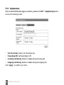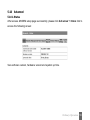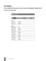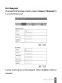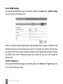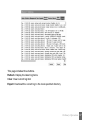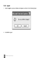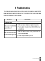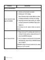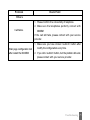
1
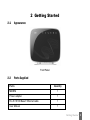
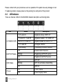
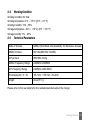
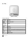
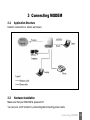
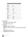
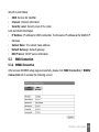
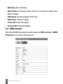
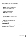
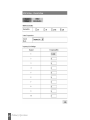
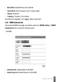
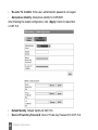
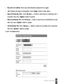
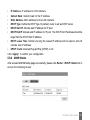
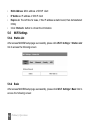
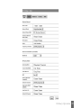
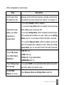
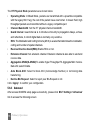
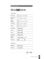
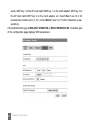
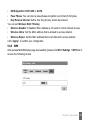
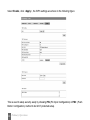
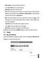
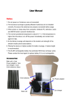
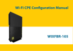
ZTE IX256
WiMAX MODEM
User Manual
1
No part of this publication may be excerpted, reproduced, translated in any form or by any
means, electronic or mechanical, including photocopying and microfilm, without the prior
written authorization of ZTE Corporation.
The manual is published by ZTE Corporation. We reserve the right to make modifications on
print errors or update specifications without prior notice.
Copyright © 2010 by ZTE Corporation
All rights reserved.
Version: V1.0
Date: Aug. 2010
Manual number: 079584501965
2
TABLE OF CONTENTS
1
2
3
4
General ............................................................................................................................ 6
1.1
Welcome ................................................................................................................ 6
1.2
Safety Precautions ................................................................................................ 6
1.3
Cleaning and Maintaining ....................................................................................... 7
1.4
Limited Warranty .................................................................................................... 7
1.5
Limitation of Liability ............................................................................................... 8
Getting Started .............................................................................................................. 9
2.1
Appearance ........................................................................................................... 9
2.2
Parts Supplied ........................................................................................................ 9
2.3
LED Indicator ........................................................................................................ 10
2.4
Working Condition ................................................................................................ 11
2.5
Technical Parameters .......................................................................................... 11
2.6
Ports ..................................................................................................................... 12
Connecting MODEM .................................................................................................... 13
3.1
Application Structure ........................................................................................... 13
3.2
Hardware Installation .......................................................................................... 13
3.2.1 Connect to LAN ....................................................................................... 14
3.2.2 Connect to Phone .................................................................................... 14
3.2.3 Connect Power Adapter .......................................................................... 14
3.2.4 Power on MODEM .................................................................................... 14
Preparation for Configuring MODEM ...................................................................... 15
4.1
TCP/IP Installation and Configuration ................................................................... 15
4.2
Checking .............................................................................................................. 18
4.2.1 Check LAN Connection ............................................................................ 18
TABLE OF CONTENTS
3
4.2.2 Cancel Proxy Server in Browser ............................................................ 18
4.2.3 Others ...................................................................................................... 19
Ordinary Operation ..................................................................................................... 20
5.1
Login .................................................................................................................... 20
5.2
Router State ......................................................................................................... 21
5.3
WAN Connection ................................................................................................. 23
5.3.1 WiMAX Connection .................................................................................. 23
5.3.2 WiMAX Information .................................................................................. 24
5.4
WIMAX Settings ................................................................................................... 25
5.4.1 Channel Settings ...................................................................................... 25
5.4.2 WiMAX Authentication ............................................................................. 27
5.5
Router .................................................................................................................. 30
5.5.1 LAN .......................................................................................................... 30
5.5.2 DHCP Clients ............................................................................................ 31
5.6
Wi-Fi Settings ....................................................................................................... 32
5.6.1 Station List ............................................................................................... 32
5.6.2 Basic ........................................................................................................ 32
5.6.3 Advanced ................................................................................................ 36
5.6.4 Security .................................................................................................... 39
5.6.5 WPS .......................................................................................................... 43
5.7
Firewall ................................................................................................................ 45
5.7.1 Mac/Ip/Port Filtering .................................................................................. 45
5.7.2 URL Filter .................................................................................................. 48
5.7.3 Time Filtering ............................................................................................ 49
5.7.4 Fort Forwarding ....................................................................................... 49
5
4
TABLE OF CONTENTS
6
7
5.7.5 DMZ .......................................................................................................... 51
5.7.6 System Security ...................................................................................... 52
5.7.7 Advanced Settings .................................................................................. 52
5.8
VPN ...................................................................................................................... 53
5.9
VoIP ...................................................................................................................... 54
5.9.1 User Details .............................................................................................. 54
5.9.2 Advanced ................................................................................................ 57
5.9.3 Supplementary ......................................................................................... 58
5.10 Advanced ............................................................................................................ 59
5.10.1 Status ....................................................................................................... 59
5.10.2 Statistics .................................................................................................. 60
5.10.3 Management ............................................................................................. 61
5.10.4 Time .......................................................................................................... 62
5.10.5 Upgrade ................................................................................................... 63
5.10.6 Remote Upgrade ...................................................................................... 63
5.10.7 Restore .................................................................................................... 65
5.10.8 Reboot ...................................................................................................... 65
5.10.9 DDNS Settings .......................................................................................... 66
5.10.10 System Log ........................................................................................... 66
5.11 Logout ................................................................................................................. 68
Troubleshooting .......................................................................................................... 69
Appendix Glossary ..................................................................................................... 72
TABLE OF CONTENTS
5
1 General
1.1
Welcome
Thanks for choosing the ZTE IX256 WiMAX MODEM (hereinafter referred to as “MODEM”). To
get the most from your MODEM and to keep it in the best condition, please read this manual
carefully.
The pictures, symbols and contents in this manual are for reference only. They might not be
completely identical with your MODEM. ZTE operates a policy of continuous development. We
reserve the right to update the technical specifications in this document at any time without
prior notice.
1.2
Safety Precautions
Some electronic devices may be susceptible to electromagnetic interference. Locate the
MODEM away from TV set, radio and other electronic equipment to avoid electromagnetic
interference.
The MODEM may interfere with medical devices like hearing aids and pacemakers. Consult
with a physician or the manufacturer of the medical device before using the MODEM.
Do not use your MODEM in dangerous environments such as oil or chemical factories where
there are explosive gases or explosive products being processed.
Please use original accessories or accessories that are authorized by your Equipment Provider.
Unauthorized accessories may affect the MODEM performance, damage the MODEM or
cause danger to you.
Do not attempt to dismantle the MODEM. There are no user serviceable parts.
6
General
Do not immerse the MODEM in any liquid.
Do not place objects on top of the MODEM. This may lead to overheating of the device.
The MODEM must be placed in ventilation environment for use.
Do not expose the MODEM to direct sunlight or store it in hot areas. High temperature can
shorten the life of electronic devices.
Do not touch the antenna while calling.
Do not allow children to play with the MODEM or charger.
Keep the length of the cable between the MODEM and the phone less than 33 feet.
The MODEM is for indoor use only. Do not use the MODEM outside. Do not connect telephone
extensions which run outside of the building. These can result in lightning damage to your
unit.
This device cannot be used with handheld PDA (personal digital assistants).
1.3
Cleaning and Maintaining
Use an antistatic cloth to clean the MODEM. Do not use chemical or abrasive cleanser as
these could damage the plastic case. Turn off your MODEM before you clean it.
Do not use your MODEM during a thunderstorm. Remove the mains power pack from the wall
socket.
Please do not touch the antenna with your hand during conversation. Covering the antenna
may affects call quality, may cause the MODEM to operate at higher power level than needed.
1.4
Limited Warranty
This warranty does not apply to defects or errors in the Product caused by:
(a) Reasonable MODEM Appearance Disfiguration.
General
7
(b) End User’s failure to follow ZTE’s installation, operation or maintenance instructions or
procedures.
(c) End User’s mishandling, misuse, negligence, or improper installation, disassemble, storage,
servicing or operation of the Product.
(d Modifications or repairs not made by ZTE or a ZTE-certified individual.
(e) Power failures, surges, fire, flood, accident, actions of third parties or other events
outside ZTE’s reasonable control.
(f) Usage of products of third Parties, or usage in conjunction with third party products
provided that such defects is due to the combined usage.
(g) Any other cause beyond the range of normal usage for Products. End User shall have no
right to reject, return, or receive a refund for any Product from ZTE under the abovementioned situations.
This warranty is end user’s sole remedy and ZTE’s sole liability for defective or nonconforming items, and is in lieu of all other warranties, expressed, implied or statutory, including but
not limited to the implied warranties of merchantability and fitness for a particular purpose,
unless otherwise required under the mandatory provisions of the law.
1.5
Limitation of Liability
ZTE shall not be liable for any loss of profits or indirect, special, incidental or consequential
damages resulting from or arising out of or in connection with using of this product, whether
or not ZTE had been advised, knew or should have known of the possibility of such damages,
including, but not limited to lost profits, interruption of business, cost of capital, cost of
substitute facilities or product, or any downtime cost.
8
General
2 Getting Started
2.1
Appearance
Front Panel
2.2
Parts Supplied
Parts
Quantity
MODEM
1
Power adapter
1
RJ-45 10/100 BaseT Ethernet cable
1
User Manual
1
Getting Started
9
Please contact with your provider as soon as possible if the parts have any damage or lost.
If replacing product, please preserve the packing box and parts of the product.
2.3
LED Indicator
There are total six LEDs for the MODEM, detailed description as following table.
LED
1,2,3 WiMAX CINR
4 VoIP/FoIP Status
5 WiFi Status
6 Power
10 Getting Started
Status
Description
1,2,3 Leds On
Signals is strong: CINR>=27
1,2 Leds On, 3 Led Off
Signals is medium: 13<=CINR<=27
I Led On, 2,3 Leds Off
Signals is weak: 9<=CINR<=13
1,2,3 Leds Off
No Signal, CINR<9
1 Led blinking
Connecting to WiMAX network
Off
Hook on/Out of Service
Blinking
Registering VoIP/FoIP service
On
Registered VoIP/FoIP service
Off
WiFi Off
Blinking
WiFi On and data is transmitting
On
WiFi On
ON
Power Supply
Off
Power Supply Failure
2.4
Working Condition
Working Condition for Host
Working temperature: 0°C ~ +55°C [32°F ~ 131°F]
Working humidity: 10% ~ 85%
Storage temperature: -40°C ~ +70°C [-40°F ~ 158 °F]
Storage humidity: 5% ~ 95%
2.5
Technical Parameters
Mode of Access
WiMAX (Worldwide Interoperability for Microwave Access)
WiMAX Protocol
802.16e(IEEE 802.16-2005)
WiFi protocol
IEEE 802.11b/n/g
WiMAX Frequency Range
2496MHz~2690MHz
WiFi Frequency Range
2400MHz~2483.5MHz
Dimensions (W × H × D)
201.7mm × 155.7mm × 54.8mm
Weight
About 511 g
Please refer to the real objects for the related parameters about the charger.
Getting Started 11
2.6
Ports
All ports are in back panel.
Port Indicator
Description
External power socket
LAN1,LAN2,
LAN port
LAN3,LAN4
PHONE
Phone port
Reset
Reset button
WPS
WPS button is used to start WiFi Protected Setup authentication process.
ON/OFF
WLAN button
ANT
Antenna connector
12 Getting Started
3 Connecting MODEM
3.1
Application Structure
Network connection is shown as follows:
3.2
Hardware Installation
Make sure that your MODEM is powered off.
You can turn on/off modem by connecting/disconnecting power cable.
Connecting MODEM 13
3.2.1 Connect to LAN
1. Connect to LAN via Network Cable
2. Plug one end of an Ethernet network cable into LAN ports on the back of the MODEM, and
plug the other end into an Ethernet port on a network device, for example, PCs or other
network devices. The Ethernet cable can be crossover or straight.
3. Connect to LAN via WiFi
4. Enable the WiFi function and make sure that your PC has been installed wireless network
card, and then use your PC to search for the SSID of MODEM to connect with it.
Note:Don’t insert phone cable into LAN ports.
3.2.2 Connect to Phone
Connect phone cable to PHONE port of MODEM.
3.2.3 Connect Power Adapter
Connect the included power adapter to the MODEM power port, and then plug the power
adapter into an electrical outlet. The Power LED on the front panel will light up when the
adapter is connected properly.
Note:
Make sure you use the power adapter that is supplied with the MODEM. Use of a different
power adapter could damage the MODEM.
3.2.4 Power on MODEM
Turn on the modem.
14 Connecting MODEM
4 Preparation for Configuring MODEM
Usually, MODEM has been configured by service provider and you can use it directly. But in
some instance, you need configure MODEM by yourself.
4.1
TCP/IP Installation and Configuration
Installation
If TCP/IP protocol is not installed, please install it first. Please refer to installation steps in
Windows XP as follows (For classic start menu):
1. Select Start Settings Control Panel Network Connections.
2. Double-click <Local Area Connection> and click <Properties>.
3. Click <Install...> and double-click <Protocol>.
Preparation for Configuring MODEM 15
16 Preparation for Configuring MODEM
4. Select <Internet Protocol (TCP/IP)> and click <OK>.
Configuration (For classic start menu)
1. Click <Start> and select <Settings>, then click <Network Connections>.
2. Double-click <Local Area Connection> and click <Properties>.
3. Double-click <Internet Protocol (TCP/IP)> and select <Obtain an IP address
automatically>, <Obtain DNS server address automatically>.
Preparation for Configuring MODEM 17
Note:
If the service provider provides DNS IP address, please select <Use the following DNS
server addresses> and enter the specified IP address.
4.2
Checking
4.2.1 Check LAN Connection
1. Click <Start> and <Run>. In the Open field, enter command. Press the Enter key or
click the <OK> button. In the command prompt, type ping 192.168.0.1 and press the
Enter key.
2. If you get a reply as follows, the LAN connection is ok.
3. If you get a reply as follows, please check the LAN and TCP/IP configuration Refer to
chapter 3.2 and chapter 4.1 in detail.
4.2.2 Cancel Proxy Server in Browser
For classic start menu:
1. Select Start Settings Control Panel Internet Options.
18 Preparation for Configuring MODEM
2. Select <Connections>.
3. Click the <LAN Settings> button and remove anything that is checked.
4. Click the <Cancel> button to go back to the previous screen.
5. Click the <OK> button to confirm canceling proxy server in browser.
4.2.3 Others
Sometimes you also need several parameters, please ask your service provider in detail.
Preparation for Configuring MODEM 19
5 Ordinary Operation
5.1
Login
To access the Web-based Utility of the MODEM, launch Internet Explorer and enter the
MODEM’s default IP address (192.168.0.1) in the address field, then press the Enter key. A
screen will appear asking you for your User Name and Password (detail as following
picture). Enter admin in the Username field and admin in the Password field. Then click the
<login> button.
20 Ordinary Operation
Note: If you select Save after you give user name and password, the router will save them,
next time when you want to log in the router with the same user name and password, what
you need to do is click <Login>.
When you access the MODEM setup page, the first screen you see as following:
The whole interface is divided into two parts, and related functions can be executed by
operation in the related areas.
• Index area: Show configuration list for your router.
• Content area: Show the detail configuration.
5.2
Router State
After access MODEM setup page successfully, please click Router State link to access the
following screen:
Ordinary Operation 21
WiMAX Information
• Network Provider: Network provider information.
• Network Type: The type of network.
WAN Information
• WiMAX Status: WiMAX network information.
• IP Address: IP address for WAN connection. It is same IP address as the WiMAX
address.
• Primary DNS: Primary DNS address.
• Secondary DNS: Secondary DNS address.
22 Ordinary Operation
WLAN Current Status
• SSID: Service Set Identifier
• Channel: Channel information.
• Security Level: Security level of the router
LAN and WLAN Information
• IP Address: IP address for WAN connection. It is the same IP address as the WiMAX IP
Address
• Subnet Mask: The subnet mask address
• Default Gateway: Default gateway.
• DHCP Server: DHCP server information.
5.3
WAN Connection
5.3.1 WiMAX Connection
After access MODEM setup page successfully, please click WAN Connection WiMAX
Connection link to access the following screen:
Ordinary Operation 23
•
•
•
•
•
•
WAN Status: Wan current status
WAN IP Address: IP address for WAN connection. It is the same IP address as the
WiMAX IP Address
WAN Netmask: Net mask assigned by DHCP server
WAN Gateway: Gateway IP address
Primary DNS: Primary DNS address
Secondary DNS: Second DNS address
5.3.2 WiMAX Information
After access MODEM setup page successfully, please click WAN Connection WiMAX
Information link to access the following screen:
24 Ordinary Operation
WiMAX Information use to view WiMAX network information.
• WAN IP address: IP address for WAN connection. It is the same IP address as the
WiMAX IP Address
• BSID: Base Station ID of the MODEM connected
• Cell ID: Cell ID of the MODEM connected
• Frequency: Frequency information
• Tx Bytes: Transmission flow statistic
• Rx Bytes: Receiver flow statistic
• Connection Status: Current connection status
• Connection Duration: Duration of time for connection
• Connection RSSI: Receive signal strength indicator
• Tx Power: Transmission power
• PER: Packet error ratio
• CINR: Carrier to interference and noise ratio
5.4
WIMAX Settings
5.4.1 Channel Settings
After access MODEM setup page successfully, please click WiMAX Settings Channel
Settings link to access the following screen:
Ordinary Operation 25
26 Ordinary Operation
• Bandwidths: Bandwidth lists can be selected.
• Search Mode: Select Frequency List or Frequency Band.
• Channel: Channel ID.
• Frequency: Frequency of the channel.
After finish the configuration, click <Apply> button to take effect.
5.4.2 WiMAX Authentication
After access MODEM setup page successfully, please click WiMAX Settings WiMAX
Authentication link to access the following screen:
1. EAP-MD5
•
•
Default Identity: Default Identity for EAP-MD5
Default Password: Default Password for EAP-MD5
Ordinary Operation 27
• Re-enter To Confirm: Enter user authentication password once again.
• Anonymous Identity: Anonymous identity for EAP-MD5
After finishing the related configuration, click <Apply> button to take effect.
2. EAP-TLS
•
•
Default Identity: Default Identity for EAP-TLS
Device Private Key Password: Device Private Key Password for EAP-TLS
28 Ordinary Operation
•
•
•
Re-enter to Confirm: Enter user authentication password once again.
After finishing the above configuration, click <Apply> button to take effect.
Device Private Key File : Click <Browse…> button to select device private key file in
local disk, then click <Update> button to upload
• Device Certificate File: Click <Browse…> button to select device certificate file in local
disk, then click <Update> button to upload
• CA Certificate File: Click <Browse…> button to select CA certificate file in local disk,
then click <Update> button to upload
3. EAP-TTLS/MSCHAPv2
Ordinary Operation 29
•
•
•
•
•
•
Default Identity: default identity for EAP-TTLS/MSCHAPv2
Default Password: default password for EAP-TTLS/MSCHAPv2
Re-enter to Confirm: Enter user authentication password once again
Anonymous Identity: anonymous identity for EAP-TTLS/MSCHAPv2
After finishing the above configuration, click <Apply> button to take effect.
CA Certificate File: Click <Browse…> button to select CA certificate file in local disk,
then click <Update> button to upload
5.5
Router
5.5.1
LAN
After access MODEM setup page successfully, please click Router LAN link to access the
following screen:
30 Ordinary Operation
•
•
•
•
•
•
IP Address: IP address for LAN interface.
Subnet Mask: Subnet mask for the IP address.
MAC Address: MAC address for the LAN interface.
DHCP Type: Define the DHCP type. By default, router is set as DHCP server.
DHCP Start IP: Allocate start IP address for IP pool.
DHCP End IP: Allocate end IP address for IP pool. The DHCP End IP address should be
larger than the DHCP Start IP address.
• DHCP Lease Time: Define how long the leased IP address will be expired, and will
relocate new IP address.
• UPNP: Enable Universal Plug and Play (UPNP) or not.
Click <Apply> to confirm your configuration.
5.5.2 DHCP Clients
After access MODEM setup page successfully, please click Router DHCP Clients link to
access the following screen:
Ordinary Operation 31
•
•
•
•
MAC Address: MAC address of DHCP client
IP Address: IP address of DHCP client
Expires in: The left time for lease, if this IP address is static bound, then demonstrated:
Infinity
Click <Refresh> button to refresh the information.
5.6
Wi-Fi Settings
5.6.1 Station List
After access MODEM setup page successfully, please click Wi-Fi Settings Station List
link to access the following screen:
5.6.2 Basic
After access MODEM setup page successfully, please click Wi-Fi SettingsBasic link to
access the following screen:
32 Ordinary Operation
Ordinary Operation 33
•
•
•
•
•
•
•
•
Wi-Fi On/Off: Enable Wi-Fi or not.
Network Mode: If all of the wireless devices connect with this router in the same
transmission mode, performance will be improved by choosing the appropriate wireless
mode.
Network Name(SSID): Service Set Identifier (SSID). Enter a string less than 32 characters as the name for your wireless local area network(WLAN).
Broadcast Network Name(SSID): Disable or Enable(Default) this function. If Enable is
selected, the router broadcasts the SSID, and other devices can detect and connect to it.
AP Isolation: When Enabled is selected, each of your wireless client will not be able to
communicate with each other.
BSSID: MAC address of the Wi-Fi.
Frequency(Channel): Choose the appropriate channel to optimize the performance
and coverage of your wireless network.
WDS Mode: WDS enable router to communicate with other APs, WDS connection is twoway communication, APs should know each others wireless MAC address. And make
sure that all APs share the same channel.
34 Ordinary Operation
WDS configuration is shown below:
Step
1.Set the same SSID
and channel for APs
2.Select WDS mode:
Disable, Lazy Mode,
Bridge Mode or
Repeater Mode
Description
Manually set the SSID and channel is strongly recommended.
And select the known channel from channel 1 to channel 14.
·If you select Disable, WDS is disabled.
·If you select Lazy Mode,WDS is enabled, and set wireless
MAC address only on the peer APs.
·If you select Bridge Mode, WDS is enabled, and set the peer
APs wireless MAC address on router. When you set Bridge
Mode, your PC can not search SSID of AP after connected.
·If you select Repeater Mode, WDS is enabled, and set the
peer APs wireless MAC address on router. When you set Repeater Mode, your PC can search SSID of AP after connected.
3.Select Phy mode:
CCK,OFDM,HTMIX or
GREENFIELD
CCK: 802.11b
OFDM: 802.11g
HTMIX: 802.11b/g/n Mixed Mode
GREENFIELD: 802.11n
4.Select Encryp Type:
WEP,TKIP,AES
If you select NONE, all the data transmitted without encryption,
and other station can access router.
5.Set AP MAC
Address on router
Only Repeater Mode and Bridge Mode need this.
Ordinary Operation 35
The HT Physical Mode parameters are shown below:
• Operating Mode: In Mixed Mode, packets are transmitted with a preamble compatible
with the legacy 802.11a/g, the rest of the packet has a new format. In Green Field, high
throughput packets are transmitted without a legacy compatible part.
• Channel Bandwidth: Set the HT physical channel bandwidth.
• Guard Interval: Guard interval is to introduce immunity to propagation delays, echoes
and reflections, to which digital data is normally very sensitive.
• MCS: The Modulation and Coding Scheme (MCS) is a value that determines the modulation,
coding and number of spatial channels.
• Reverse Direction Grant(RDG):Enable RDG or not.
• Extension Channel: Set extension channel. Extension channel is also able to send and
receive data.
• Aggregation MSDU(A-MSDU):To enable Hyper Throughput TX Aggregate MAC Service
Data Unit ,select Enable.
• Auto Block ACK: Select to block ACK (Acknowledge Number) or not during data
transferring.
• Decline BA Request: Select to reject peer BA-Request or not.
Click <Apply> to confirm your configuration.
5.6.3 Advanced
After access MODEM setup page successfully, please click Wi-Fi Settings Advanced
link to access the following screen:
36 Ordinary Operation
Ordinary Operation 37
•
•
•
•
•
•
•
•
•
•
Beacon Interval: The router broadcasts beacon message to announce that it has buffered frames to deliver. The default value is 100 (ms). Beacons are packets sent by an
access point to synchronize a wireless network. Specify a beacon interval value. is
recommended.
Data Beacon Rate(DTIM): A Delivery Traffic Indication Message(DTIM) informs next
clients to listen to broadcast and multicast messages.
Fragment Threshold: This value should remain at its default value of 2346. If you
experience a high packet error rate, you may slightly increase your fragment threshold.
Setting the fragment threshold too low may result in poor performance.
RTS Threshold: Request To Send(RTS) threshold should be remained as the value of
2347. If you encounter inconsistent data flow, only minor modifications are recommended.
TX Power: Transmit power should be remained as the value of 100.
Short Preamble: The length of CRC block in the frames during the wireless communication.
Short Slot: To indicate that 802.11g is using a shot time slot because there is no legacy
station(802.11b) present.
Tx Burst: Tx burst allows router to deliver better throughput in the same period and
environment in order to increase speed.
Pkt_Aggregate: Increase efficiency by aggregating multiple application packets data
into a single transmission frame. In this way, 802.11n networks can send multiple data
packets with the fixed overhead cost in just a single frame.
IEEE 802.11H Support: Support IEEE 802.11H or not.
38 Ordinary Operation
The Wi-Fi Multimedia parameters are shown below:
• WMM Capable: When multimedia contents are transferred over wireless network, this
function enhances data transfer performance.
• APSD Capable: Automatic Power Save Delivery (APSD), enable or disable data flow
using APSD during transmitting for power saving.
Click <Apply> to confirm your configuration.
5.6.4 Security
After access MODEM setup page successfully, please click Wi-Fi SettingsSecurity link
to access the following screen:
Ordinary Operation 39
Unless one of these encryption modes is selected, wireless transmissions to and from your
wireless network can be easily intercepted and interpreted by unauthorized users.
The security modes are described below:
• OPEN: You can authenticate successfully with a SSID, whether it is valid or empty.
• SHARED: The WLAN clients who have the same WEP key with wireless gateway can
pass the authentication and access the wireless network.
• WEPAUTO: Select WEP security automatically.
• WPA-PSK: WPA Pre-Shared Key, Enter the Pre-Shared key as a plain text (ASCII) passphrase of at least 8 characters.
• WPA2-PSK: It is the securer version of WPA with implementation of the 802.11i standard.
• WPA-PSK/WPA2-PSK: Apply both the WPA-PSK and WPA2-PSK scheme.
If the Authentication type is OPEN, SHARED, WEPAUTO, the bottom part of the configuration
page displays parameters as shown.
40 Ordinary Operation
•
•
Encrypt Type: Select NO ENCRYPTION or WEP.
WEP Keys: At most four keys can be set in the blank. Choose the primary key index. The
primary key is the only key in use at a given time. Whatever keys you enter for an access
point, you must also enter the same keys for the client adapter in the same order. In other
Ordinary Operation 41
words, WEP key 1 on the AP must match WEP key 1 on the client adapter, WEP key 2 on
the AP must match WEP key 2 on the client adapter, etc. Select Hex if use 10 or 26
hexadecimal numbers (0-9, or A-F). Select ASCII if use 5 or 13 ASCII characters (casesensitive).
If the Authentication type is WPA-PSK, WPA2-PSK or WPA-PSK/WPA2-PSK, the bottom part
of the configuration page displays WPA parameters.
42 Ordinary Operation
• WPA Algorithm: TKIP, AES or AUTO.
• Pass Phrase: You can input a pass phrase encryption key format (8~64 bytes).
• Key Renewal Interval: Define how long the key should be renewed.
You can set Wireless MAC Filtering:
• Wireless Disable: If disabled, MAC address is not used to control network access.
• Wireless Allow: Set the MAC address that is allowed to access network.
• Wireless Reject: Set the MAC address that is not allowed to access network.
Click <Apply> to confirm your configuration.
5.6.5 WPS
After access MODEM setup page successfully, please click Wi-Fi Settings WPS link to
access the following screen:
Ordinary Operation 43
Select Enable, click <Apply>, the WPS settings are shown in the following figure:
This is used to setup security easily by choosing PIN (Pin Input Configuration) or PBC (Push
Button Configuration) method to do Wi-Fi protected setup.
44 Ordinary Operation
•
•
•
•
WPS Summary: Shows the WPS function status.
Click <Reset OOB> button to reset the settings.
WPS mode: Select PBC or PIN WPS mode.
PIN: There are two ways to use PIN mode, one is set PIN code on the client’s wireless
adapter (you can find the PIN code in AP PIN field of WPS Summary), and the other way
is set the client’s PIN code in Client PIN field.
• PBC: Press the WPS button of the router or select PBC, and then click <Apply>. Press
WPS button on the client wireless adapter within two minutes, and the negotiation process will be established.
• Client PIN: Enter the PIN code from the registrar or enrollee.
• Click <Apply> to save and apply the current settings.
• WPS Status: Shows the current status of the WPS function.
Note:When the security mode is SHARED or Open, you can not use WPS connection.
5.7
Firewall
5.7.1 Mac/Ip/Port Filtering
After access MODEM setup page successfully, please click Firewall Mac/Ip/Port Filtering link to access the following screen:
Ordinary Operation 45
If you select Enable, the filter settings will appear:
46 Ordinary Operation
• Default Policy: Set how to handle the packet if none of the rules matches.
• MAC address: Set the MAC address that will be filtered.
• Dest IP Address: Set the destination IP address that will be filtered.
• Source IP Address: Set the source IP address that will be filtered.
• Protocol: Set which protocol will be used for filtering.
• Dest Port Range: Set the destination port numbers that will be filtered
• Source Port Range: Set the source port numbers that will be filtered.
• Action: Set how to handle the packet if it matches with the rule.
• Comment: Type comment for the filter settings.
Note:Filtering rules are matched one by one, if met this provision, it will not continue to match
the rules listed below.
Click <Apply> to confirm your configuration. Click <Delete> to delete the rule which you
selected. Click <Reset> to clear what you select or input.
To add a new rule:
a) Select Enable and click <Apply> in the Basic Settings area.
b) Input the detail information in the Mac/Ip/Port Filtering area.
c) Click <Apply> in the Mac/Ip/Port Filtering area.
Ordinary Operation 47
5.7.2 URL Filter
After access MODEM setup page successfully, please click Firewall URL Filter
link to access the following screen:
Type URL address, and then click <Add> to add the URL address into the filtering list. The
new URL filtering item will be shown in the Current URL Filter field. Click <Delete> to delete
the rule which you selected. Click <Reset> to clear what you select or input.
48 Ordinary Operation
5.7.3 Time Filtering
After access MODEM setup page successfully, please click Firewall Time Filtering link
to access the following screen:
Select the Days and Time Range, and then click <Apply> to add the Time filtering. The new
Time filtering item will be shown in the Current Time Rules field. Click <Delete> to delete
the rule which you selected. Click <Reset> to clear what you select or input.
5.7.4 Fort Forwarding
After access MODEM setup page successfully, please click Firewall Port Forwarding
link to access the following screen:
Ordinary Operation 49
If you select Enable, the Virtual Server Settings will appear:
50 Ordinary Operation
• IP Address: Set IP address for the virtual server.
• Port Range: Set port numbers for the virtual server.
• Protocol: Set protocol for the virtual server.
• Comment: Type comment for the virtual server settings.
Select Enable, and input the detail information in the Virtual Server Settings area, and then
click <Apply> to add a new rule. Click <Delete> to delete the rule which you selected. Click
<Reset> to clear what you select or input.
5.7.5 DMZ
After access MODEM setup page successfully, please click Firewall DMZ link to access
the following screen:
If you select Enable, set the DMZ IP address ,and then click <Apply> to confirm your
configuration. You can setup a De-militarized Zone(DMZ) to separate internal network with
the Internet.
Ordinary Operation 51
5.7.6 System Security
After access MODEM setup page successfully, please click Firewall System Security
link to access the following screen:
Allow or Deny the remote management function and Enable or Disable ping from WAN on
requirement, and then click <Apply>. Click <Reset> to restore the default value.
5.7.7 Advanced Settings
After access MODEM setup page successfully, please click Firewall Advanced Settings link to access the following screen:
52 Ordinary Operation
• DNS Proxy: Disable or enable to send this DNS request to high-level DNS server.
• NAT: Disable or enable the NAT in internal network.
Click <Apply> to confirm.
5.8
VPN
After access MODEM setup page successfully, please click VPN link to access the following
screen:
Ordinary Operation 53
• Select Mode: Select L2TP or PPTP.
• L2TP/PPTP Server IP Address: Input server IP address.
• User Name: Input user Name
• Password: Input password.
• Select Operation: Select the operation, Connect or Disconnect.
• VPN Status: VPN current status.
Click <Apply> to confirm.
5.9
VoIP
5.9.1 User Details
After access MODEM setup page successfully, please click VoIP User Details link to
access the following screen:
54 Ordinary Operation
Ordinary Operation 55
•
SIP Register Server: A server that accepts registration requests from users. If it is
unspecified or blank, the voice port will not use a SIP registrar and will not send a
REGISTER message. The value must specify the protocol.
• SIP Domain: A SIP Domain name or IP address, defined by customer.
• SIP Realm: This is a string value provided by the ITSP, such as AVSTW, or may be a
domain name like www.zte.com.cn, defined by customer.
• SIP Port: The listening/binding port of the local User Agents for receiving and transmitting
SIP messages. By default, it sets 5060.
• SIP Proxy Mode: Enable or disable the use of SIP proxy server config parameter.
• T.38 FAX Ecoder: T.38 Fax Mode for VoIP. Enable this item to ensure the successful of
Fax.
• Display Name: Display name for using in the SIP URI.
• User Name: User name for using in the SIP URI for the respective appearance.
• Authorized User Name: This is for authentication with a registrar.
• Authorization Password: This is a password for authentication with a registrar.
• VOIP Register Status: Show the register status of SIP server.
Click <Apply> to confirm your choice.
56 Ordinary Operation
5.9.2
Advanced
After access MODEM setup page successfully, please click VoIP Advanced link to
access the following screen:
• Outbound Mode: Enable or disable the use of SIP outbound server config parameter.
• STUN Mode: Enable or disable the use of STUN server to discover NAT mapping.
• Reregister Every: Expires value in seconds for a REGISTER request.
• Appearance Displayname: Be used in SIP REGISTER.
• Encoder: Used for SIP negotiation.
Click <Apply> to confirm your choice.
Ordinary Operation 57
5.9.3 Supplementary
After access MODEM setup page successfully, please click VoIP Supplementary link to
access the following screen:
• Call Forwarding: Select call forwarding way,
• Forwarding URI: Call forwarding to URI.
• Incoming Call Barring: Enable or disable barring incoming call.
• Outgoing Call Barring: Enable or disable barring the outgoing call.
Click <Apply> to confirm your choice.
58 Ordinary Operation
5.10 Advanced
5.10.1 Status
After access MODEM setup page successfully, please click Advanced Status link to
access the following screen:
View software version, hardware version and system up time.
Ordinary Operation 59
5.10.2 Statistics
After access MODEM setup page successfully, please click Advanced Statistics link to
access the following screen:
60 Ordinary Operation
5.10.3 Management
After access MODEM setup page successfully, please click Advanced Management link
to access the following screen:
To set new account, type new account and password, and then click Apply to confirm your
configuration.
Ordinary Operation 61
5.10.4 Time
After access MODEM setup page successfully, please click Advanced Time link to access the following screen:
• Time Set Mode: Select the time set mode.
• Manual Set Time: Set the time manually.
• SNTP Server IP: Enter a server IP for time synchronization by SNTP.
Click <Apply> to confirm your configuration to set the device time by manually, or by SNTP
sever.
62 Ordinary Operation
5.10.5 Upgrade
After access MODEM setup page successfully, please click Advanced Upgrade link to
access the following screen:
Click <Browse...>, locate the latest software version, and then click <Upgrade>.
Note: Do not upgrade software unless necessary. Wrongly upgrade action may cause
router malfunction or can not work.
5.10.6 Remote Upgrade
After access MODEM setup page successfully, please click Advanced Remote Upgrade link to access the following screen:
Ordinary Operation 63
•
Upgrade Mode: Select upgrade mode. FTP or TFTP is available. If select TFTP, you don’t
need user authorization.
• Server Name: Remote FTP/TFTP server IP address.
• Server Port: The port of Remote FTP/TFTP server address.
• FTP Username: User name for the FTP server.
• FTP Password: Password for the FTP server.
• Remote Path/File Name: Locate upgrade file in FTP server. If TFTP is selected, you just
need to type in file name.
Click <Apply> to confirm your configuration.
64 Ordinary Operation
5.10.7 Restore
After access MODEM setup page successfully, please click Advanced Restore link to
access the following screen:
Restore to set all the settings to their factory default values, and the device will restart.
5.10.8 Reboot
After access MODEM setup page successfully, please click Advanced Reboot link to
access the following screen:
You can reboot the Home Gateway by webUI remotely, if the Gateway is not around you.
Ordinary Operation 65
5.10.9 DDNS Settings
After access MODEM setup page successfully, please click Advanced DDNS Settings
link to access the following screen:
DDNS is a dynamic domain analysis system. After applying DDNS, a dynamic IP address to the
mainframe also can provide domain name services. For example, the mainframe through dialup or XDSL DHCP server gets IP address and domain names dynamically. Enable and configure DDNS so the host’s IP address changes will not affect the users who visit through the
domain name.
5.10.10 System Log
After access MODEM setup page successfully, please click Advanced System Log link
to access the following screen:
66 Ordinary Operation
This page includes three buttons.
Refresh: Display the latest log items
Clear: Clear current log item
Export: Download the current log to the local specified directory
Ordinary Operation 67
5.11 Logout
1. Select Logout, a pop-up windows will appear as shown in the following figure :
2. Click OK to log out.
68 Ordinary Operation
6 Troubleshooting
This chapter lists some problems that you might encounter while installing or using MODEM,
please read following relative information at first. If the problem still can not be solved, please
contact with distributor or service provider.
Problem
Check Point
Indicator light
After power on the MODEM,
power LED is off.
After insert Ethernet cable,
the LAN indicator light is off.
1. Make sure power adapter is original accessories.
2. Power adapter correctly connect with MODEM and wall
socket/power.
1. Make sure Ethernet cable correctly connect with computer/HUB and MODEM.
2. Confirm computer/HUB is power on.
Troubleshooting 69
Problem
Check Point
Access network failure
Can not access the setup
page of the MODEM
Can not access Internet
70 Troubleshooting
1. Verify the LAN connection successful.
2. Checking your TCP/IP settings.
Refer to Windows Help for details. Make sure Obtain
IP address automatically is selected in the settings.
3. Using Ping command to make sure that your computer
is properly connected to the MODEM. Please refer to
chapter 4.2.
If it still does not work, please contact your service
provider.
1. Please check your PC’s settings and connection according to the above advices, make sure that your PC
can access MODEM setup page.
2. If PC is configured correctly and only can access MODEM setup page, please check your MODEM. Detailed
refer to chapter 5.
If MODEM configured correctly, but still not work, please
contact your service provider.
Problem
Check Point
Others
Call failure
Web page configuration lost
after restart the MODEM
1. Please Confirm the connectivity of telephone.
2. Make sure the telephones perfectly connect with
MODEM.
If the call still fails, please contact with your service
provider.
1. Make sure you have clicked <submit> button after
modify the configuration every time.
2. If you click <submit> button, but the problem still exist,
please contact with your service provider.
Troubleshooting 71
7 Appendix Glossary
AES
Advanced Encryption Standard
DNS
Domain Name Server: it can provide the service that network node name can be translated to
network IP address in the internet.
DDNS
Dynamic Domain Name Server.
DHCP
Dynamic Host Configuration Protocol.
DMZ
Demilitarized Zone.
Internet
Global network, Use to exchange data, news and viewpoints within millions of computer.
IP Address
32 bit address, Use to identify one computer in TCP/IP.
ITSP
The sever of SIP network
Use to connect some communication equipment (computer, MODEM and printer) within one
room, school or other limited region.
72 Appendix Glossary
MAC Address
The Media Access Control (MAC) address is a unique number assigned by the manufacturer
to any Ethernet networking device, such as a network adapter, that allows the network to
identify it at the hardware level. For all practical purposes, this number is usually permanent.
Unlike IP address, which can change every time a computer log in the network, the MAC
address of a device stays the same, making it a valuable identifier for the network.
NAT
Network Address Translation.
Protocol
Communication protocol: it is a rule that network equipment must follow for mutual communicating to transfer, transmit and receive data.
SNTP
Simple Network Time Protocol.
SIP
Session Initiated Protocol
TCP/IP
Transmission Control Protocol/Internet Protocol: basic communication protocol of network
communication, but TCP/IP defines one group of protocol, not only include TCP and IP.
TKIP
Temporal Key Integrity Protocol, a security protocol used in the IEEE 802.11 wireless networking standard..
Appendix Glossary 73
UDP
User Data Protocol: packet exchanging communication protocol in internet, its default under
layer protocol is IP, provide simple protocol mechanism when transfer information to another
user.
WAN
Wide Area Network.
WEP
Wired Equivalent Privacy
WiMAX
Worldwide Interoperability for Microwave Access.
74 Appendix Glossary