1
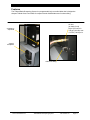
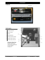
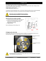
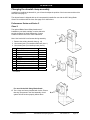
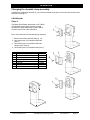
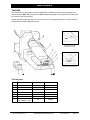
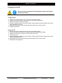
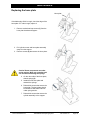
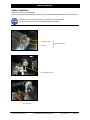
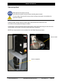
TIDLAND SLITTING SOLUTIONS
Tidland Blade Sharpening System
Installation, Operation and Maintenance
EN
MI 727946 1 G
CONTENTS
Contact information ................................................................................................................................. 2
Important safety information .................................................................................................................... 3
General................................................................................................................................................ 3
Intended purpose ................................................................................................................................ 3
Safety symbols .................................................................................................................................... 5
Maximum inputs .................................................................................................................................. 6
Transporting the unit ........................................................................................................................... 6
Safety instructions for operating personnel......................................................................................... 7
Safety instructions for operation.......................................................................................................... 8
Safety instructions for maintenance.................................................................................................... 9
Notice about particular dangers ........................................................................................................ 10
Overview................................................................................................................................................ 11
Features ............................................................................................................................................ 11
Specifications .................................................................................................................................... 13
Recommended tools and spare parts ............................................................................................... 13
Installation requirements ....................................................................................................................... 14
Unit weight......................................................................................................................................... 14
Power ................................................................................................................................................ 14
Air supply........................................................................................................................................... 14
Operation ............................................................................................................................................... 15
Counters............................................................................................................................................ 15
Operating the blade sharpening system ........................................................................................... 16
Configuring the blade sharpening system......................................................................................... 17
Adjusting the hone plate assembly ............................................................................................... 17
Configuring the drive hub.............................................................................................................. 17
Changing the cartridge dovetail clamp assembly ............................................................................. 18
Removing the existing dovetail clamp .......................................................................................... 18
Maintenance .......................................................................................................................................... 24
Changing the tool bit edge ................................................................................................................ 24
Replacing the hone plate .................................................................................................................. 26
Sensor locations................................................................................................................................ 27
Vacuum system................................................................................................................................. 28
Troubleshooting..................................................................................................................................... 29
Declaration of Conformity ...................................................................................................................... 31
CONTACT INFORMATION
Manufactured by
Authorized Representative
Tidland
Fife-Tidland GmbH
th
2305 SE 8 Avenue
Camas WA 98607
Tel.
360.834.2345
800.426.1000
Max-Planck-Strasse 8-10
65779 Kelkheim
Germany
Siemensstrasse 13-15
48683 Ahaus
Germany
Tel.
+49.6195.7002.0
+49.6195.7002.933
www.maxcessintl.com
Tidland Blade Sharpening System
MI 727946 1 G
Page 2
IMPORTANT SAFETY INFORMATION
General
The Tidland Blade Sharpening System has been built state-of-the-art and complies with the generally
recognized and applicable safety regulations. Injury to the operator (or to third parties) or damage to
the unit may occur if it is
• operated by untrained personnel
• used for unintended purposes
• maintained and serviced improperly.
Read and understand all instructions before operating the unit. Failure to follow instructions may cause
the unit to function incorrectly and can cause serious injury.
While operating the unit, follow all existing plant safety instructions and/or requirements. Compliance
with federal, state, and local safety regulations is your responsibility. Be familiar with them and always
work safely.
Read and understand all safety warnings and instructions before operating machine.
Keep the instructions near the machine at all times.
Maxcess Technical Services 405.821.9052
Tidland Customer Service (USA) 800.426.1000 (Outside USA) 360.834.2345
Intended purpose
The Blade Sharpening System is intended exclusively for the sharpening of Tidland Class II and
Class III compound bevel dished blades installed in Tidland blade cartridges and used in shear slitting.
There is no other intended purpose.
The Blade Sharpening System may only be operated within the technical limits and only with
equipment that has been designated and cleared by Tidland.
These instructions must be observed and followed. Another application or an application exceeding
these designated applications is considered unintended.
The operator of the Blade Sharpening System is liable for any and all resulting damages. This applies
also to unauthorized modifications made to the Blade Sharpening System. The intended use also
includes the observance of any and all notices contained in these installation instructions regarding:
•
Safety
•
Installation
•
Operation and
•
Maintenance
www.maxcessintl.com
Tidland Blade Sharpening System
MI 727946 1 G
Page 3
IMPORTANT SAFETY INFORMATION
Information about safety instructions
The safety instructions and symbols described in this section are used
in these operating instructions. They are used to avoid possible dangers
for users and to prevent material damage.
SIGNAL WORD
Source of danger and its results
Avoiding dangers
The signal word DANGER refers to the danger of death or serious
bodily injuries.
The signal word WARNING refers to the danger of moderate to severe
bodily injuries.
The signal word CAUTION refers to the danger of slight to moderate
bodily injuries or material damage.
www.maxcessintl.com
Tidland Blade Sharpening System
MI 727946 1 G
Page 4
IMPORTANT SAFETY INFORMATION
Safety symbols used in this manual
Wear ear and/or eye protection while operating machine.
Warning
Unit weight is 576 lbs (261 kg)
Cart weight is 114 lbs (52 kg).
Do not lift manually.
Warning
Unit is top heavy.
Unit can tip if cart comes to sudden stop.
Use fixed casters at one end of cart to ensure unit is rolled in the most stable
direction.
Warning
Knife blades are sharp.
Can cause serious injury to hands.
Wear protective gloves when handling knife blades.
Warning
Pinching hazard.
Can cause serious injury to hands.
Wait until all moving parts come to a complete stop before reaching into machine.
Danger
High voltage.
Risk of electrical shock or machine damage; do not open electrical drawer.
Service to be performed by Maxcess qualified technicians only.
Caution
Blade splinters and chips are sharp.
Use protective gloves when handling waste material.
For your safety, ensure that the vacuum hose is always connected to a
manufacturer's approved receptacle.
Information
This mark identifies a process and/or operator steps. Execute steps in sequence top
to bottom. Observance of correct procedures will assure a safe, sound and efficient
handling of the knifeholder.
Notices and symbols directly attached to the Blade Sharpening System, such as
danger signs, operating signs, arrows indicating a direction of rotation, component
identification, etc., must be strictly observed. Notices and symbols directly attached
to the Blade Sharpening System should not be removed and shall be maintained in a
completely legible condition.
www.maxcessintl.com
Tidland Blade Sharpening System
MI 727946 1 G
Page 5
IMPORTANT SAFETY INFORMATION
Maximum inputs
110 VAC Blade Sharpening System
The nominal 110 Volt AC Blade Sharpening System power input shall not exceed 150 volts with a
maximum potential to ground of 150 volts (this applies to cord and plug connected units). The power
source shall have a fuse or circuit breaker size of 20 amperes maximum. The short circuit current
rating (SCCR) is 10 kiloamperes.
220 VAC Blade Sharpening System
The nominal 220 Volt AC Blade Sharpening System power input shall not exceed 250 volts with a
maximum potential to ground of 300 volts. (This applies to cord and plug connected units.) The power
source shall have a fuse or circuit breaker size of 10 amperes maximum. The short circuit current
rating (SCCR) is 10 kiloamperes.
The air input is 150 psi (10.3 bar) maximum; 15 CFM (7.08 l/s) minimum.
The optimal operating range is 80-100 psi (5.5-6.9 bar).
Clean, non-lubricated, dry air is required for optimal performance of the Blade Sharpening System.
Transporting
Unit weight with cart is 690 lbs (313 kg).
Do not lift manually.
Unit is top heavy.
If your unit is equipped with swivel casters, always push the Blade Sharpening System on
cart in the lengthwise direction for maximum stability.
Store and operate the Blade Sharpening System on a flat, horizontal surface
fixed casters
swivel casters
www.maxcessintl.com
Tidland Blade Sharpening System
MI 727946 1 G
Page 6
IMPORTANT SAFETY INFORMATION
Safety instructions for operating personnel
The Blade Sharpening System may be operated only in a fully assembled condition and only as
intended. Unsafe operating conditions must be resolved immediately.
Before operating the Blade Sharpening System, all installers, operators or maintenance personnel
must read and understand all instructions and safety warnings provided in the user manual.
Keep this manual near the Blade Sharpening System at all times.
Tidland accepts no liability for damages and accidents caused by non-observance of the operating
instructions. Follow the regulations for the prevention of accidents and all other generally recognized
safety regulations. The responsibilities for operation, maintenance and servicing of the Blade
Sharpening System should be clearly assigned and followed.
All operators and maintenance personnel must wear appropriate safety gear as designated. This may
include protective gloves, safety goggles, ear protection and protective clothing.
If safety-relevant changes to the operating performance are occurring, or if the Blade Sharpening
System malfunctions, shut the unit down immediately and report the incident.
Keep first-aid equipment (first-aid box, eye rinsing bottles, etc.) available within easy reach.
All personnel should have knowledge of the location and operation of fire extinguishers, and the
procedure for reporting and fighting fires.
During inspection, maintenance and repair of the Blade Sharpening System, refer to the instruction
manual for procedures.
Only qualified or trained personnel may operate or perform maintenance and repairs on the Blade
Sharpening System.
Personnel undergoing training and qualification may only work on the Blade Sharpening System under
supervision by trained personnel.
www.maxcessintl.com
Tidland Blade Sharpening System
MI 727946 1 G
Page 7
IMPORTANT SAFETY INFORMATION
Safety instructions for the operation of the blade sharpening
system
During all activities relating to the operation, inspection, maintenance and repair of the
Blade Sharpening System the procedures to power up and shut down as specified in
these instructions and the notices regarding maintenance must be followed.
The Blade Sharpening System may only be commissioned in a fully assembled and
operational condition.
Before operation, ensure that all protective and safety installations, such as removable
guards, are installed and fully functional. Do not bypass safety installations.
The Blade Sharpening System should be inspected for externally visible damage before
every startup.
Changes (including operational behavior) should be reported immediately to the
responsible person or the supervisor in charge.
Shut down and secure the Blade Sharpening System immediately in case of
malfunctions. Have malfunctions eliminated immediately by qualified trained
professionals.
www.maxcessintl.com
Tidland Blade Sharpening System
MI 727946 1 G
Page 8
IMPORTANT SAFETY INFORMATION
Safety instructions for maintenance
Before beginning maintenance, inform all operating personnel about maintenance
requirements and procedures. A supervisor in charge shall be designated.
Observe the timelines for regular tests or inspections as prescribed or as stated in the
installation instructions.
Suitable workshop equipment is mandatory for the execution of maintenance works.
The Blade Sharpening System must be shut down completely for maintenance, repair
and servicing activities and be secured against unexpected repowering.
Carry a flashlight in ensure sufficient illumination at the Blade Sharpening System
during maintenance.
Maintenance on pneumatic installations of the Blade Sharpening System may only be
carried out by trained professionals or by instructed personnel working under the
supervision and guidance of a trained professional.
Visually check pneumatic hoses daily for:
Damage to the outer layer (e.g. chafe marks, cuts, tears, cracks),
Deformations which do not correspond to the natural shape of the hose, in a
pressurized or depressurized condition or when bent, e.g. layer separation, bubble
formation,
Leaks (visual and acoustic check).
Visually check hose fittings daily for:
Damages or deformations of the hose fittings (impaired tightness),
Loose adjustments of the hose in the fittings,
Fitting corrosion and fatigue.
Check hoses annually in detail. Even if no damage can be identified, pneumatic hoses
should be replaced after six years.
Replace present wearing parts and filter cartridges of the pneumatic system within the
prescribed or appropriate time frames, even if no safety-relevant faults can be detected.
Always retighten threaded connections that were loosened during maintenance and
repair works. If prescribed, tighten screws with torque wrench.
If it is necessary to disassemble safety installations for maintenance or repair works,
reassemble and test safety installations immediately following the completion of
maintenance and repair.
Clean the Blade Sharpening System, particularly connections and screw fittings, of all
debris and residue at the beginning of maintenance, repair or servicing.
Do not use aggressive or solvent-containing cleaning agents. Use fiber-free cloths. Use
only mild cleaning agents. Follow manufacturer‘s instructions. Do not use organic
solvents as the risk of fires and explosions exists.
Make sure that operational and auxiliary materials are disposed of in a safe and
environmentally-friendly manner.
www.maxcessintl.com
Tidland Blade Sharpening System
MI 727946 1 G
Page 9
IMPORTANT SAFETY INFORMATION
Notice about particular dangers
Pneumatics
Only personnel with special knowledge and experiences in the pneumatics field are
permitted to work on pneumatic installations.
During maintenance works on the pneumatics system the maintenance personnel must
be fully familiar with the pneumatics circuit diagram and be fully briefed about the
potential consequences of misactions.
Inspect daily all piping, hoses and threaded connections for tightness. Shut down and
repair the Blade Sharpening System immediately if an air leak is detected.
Before beginning repair works, depressurize the pneumatic system and leave the air
lines open.
Clean debris and contamination from fittings and threaded connections of the
pneumatic system before beginning maintenance.
Maintain all safety valves regularly.
Oils, greases and other chemical substances
Observe and follow the applicable regulations and Material Safety Data Sheets
provided by the substance manufacturer regarding storage, handling, utilization and
disposal.
Noise
The declared A-rated equivalent continuous sound pressure level at the Tidland Blade
Sharpening System during operation is 78.0 dB(A) at a distance of 1 meter.
If the Blade Sharpening System is operated by itself: no ear protection is required as
personal protective gear. If the Blade Sharpening System is used in an enclosed work
space together with other installations or machinery and an increased sound pressure
level can be created in the work space, then the operator must be equipped with and
use the required protective gear.
www.maxcessintl.com
Tidland Blade Sharpening System
MI 727946 1 G
Page 10
OVERVIEW
Features
The Tidland Blade Sharpening System is a programmable logic controlled lathe that is designed to
sharpen Tidland Class II and Class III compound bevel dished blades used in shear slitting.
air inlet
(on back of unit)
80 psi (5.5 bar) min.
150 psi (10.3 bar) max.
15 CFM (7.08 l/s) min.
emergency
stop knob
vacuum
receptacle
drain hose fitting
www.maxcessintl.com
Tidland Blade Sharpening System
MI 727946 1 G
Page 11
OVERVIEW
Features
acrylic door
Interior parts
1
Cartridge drive hub
2
Vacuum nozzle
3
Tool bit
4
Honing assembly
5
Cartridge detection switch
6
Dovetail mount, Class II*
7
Dovetail mount, Class III*
* Performance Series Shear
dovetails are shown here.
Dovetail mounts for the
Class II and III e-Knifeholder
are also available.
See page 18.
www.maxcessintl.com
Tidland Blade Sharpening System
MI 727946 1 G
Page 12
OVERVIEW
Specifications
Physical dimensions
38" w x 23" h x 24" d (37 cm x 58 cm x 62 cm)
Unit weight
690 lbs (313 kg) total
Blade Sharpening System
576 lbs (261 kg)
Cart (if equipped)
114 lbs (52 kg)
Electrical
110 VAC, 60 Hz, 16 A
220 VAC, 50 Hz, 6 A
Pneumatic
80 psi (5.5 bar) minimum
150 psi (10.3 bar) maximum
15 CFM (7.08 l/s)
Air pressure, operating
80-100 psi (5.5-6.9 bar)
Noise output
78.0 dB(A) @ 1 meter
Operating temp (ambient)
104° F / 40° C
Blade diameters
Maximum
Minimum
Class II
5.906" (150 mm)
4.906" (124.6 mm)
Class III
7.874" (200 mm)
6.874" (174.5 mm)
Blade materials
D2; 52-100
Blade sharpening angles
15-35 degrees
Tool bit material
Aluminum oxide, sintered
Blade sharpening cycle time
minimum 1 minute / maximum 2 minutes
Recommended tools and spare parts
•
•
•
•
Tool bits (see page 24)
Hone plate (725665)
Hex wrenches: 4 mm, 5/32", 3/16", 1/8"
Stainless steel mesh protective gloves (Tidland PN 132084)
www.maxcessintl.com
Tidland Blade Sharpening System
MI 727946 1 G
Page 13
INSTALLATION
Installation requirements
Warning
Unit is heavy.
Do not lift manually.
Unit total weight with cart is 690 lbs (313 kg)
Transportation and installation method must be able to support this weight. Must be installed and
operated on a level surface. (Cart weight is 114 lbs.)
Power
110 VAC Blade Sharpening System
The nominal 110 Volt AC Blade Sharpening System power input shall not exceed 150 volts with a
maximum potential to ground of 150 volts. (This applies to cord and plug connected units). The power
source shall have a fuse or circuit breaker size of 20 amperes maximum. The short circuit current
rating (SCCR) is 10 kiloamperes.
220 VAC Blade Sharpening System
The nominal 220 Volt AC Blade Sharpening System power input shall not exceed 250 volts with a
maximum potential to ground of 300 volts. (This applies to cord and plug connected units.) The power
source shall have a fuse or circuit breaker size of 10 amperes maximum. The short circuit current
rating (SCCR) is 10 kiloamperes.
Air supply
80 psi (5.5 bar) minimium/150 psi (10.3 bar) maximium
15 CFM (7.08 l/s) minimum
Unit operates at 80-100 psi (5.5-6.9 bar) – factory set internal regulator
Use clean, dry, non-lubricated air.
If the supply air is too wet, water will drain from the unit through an outlet in the back, located under
the air inlet. The drain fitting accepts a 5/16" O.D. hose.
air inlet
drain hose fitting
www.maxcessintl.com
Tidland Blade Sharpening System
MI 727946 1 G
Page 14
OPERATION
Operating the blade sharpening system
Knife blades are sharp.
Can cause serious injury to hands.
Wear protective gloves when handling knife blades.
Pinching hazard.
Can cause serious injury to hands.
Wait until all moving parts come to a complete stop before reaching into machine.
For your safety, ensure that the vacuum hose is always connected to a manufacturer's
approved receptacle.
Counters
The Tidland Blade Sharpening System is equipped with two counters, located on the front of the unit, that
record the number of blades sharpened. The top counter, labeled RESET, can be reset to zero by the
operator. The bottom counter, labeled TOTAL, cannot be reset.
The Blade Sharpening System must be allowed to complete the sharpening process in order for the
counter to register. Do not open the acrylic door until all moving parts have come to a full stop. Only then
shall the door be opened and the cartridge removed.
You may wish to reset the counter whenever you change the cutting tool.
www.maxcessintl.com
Tidland Blade Sharpening System
MI 727946 1 G
Page 15
OPERATION
Operating the blade sharpening system
Operation
1. Attach the power cable to the Blade Sharpening System and plug the unit into a power source. Make
sure that the line voltage you are running matches the voltage specified on the unit nameplate.
2. To turn on the unit, pull the red emergency stop power button out. There is a 15-20 second delay
before the unit is ready to start.
Note
If the previous sharpening process was interrupted, the system will reset itself. Wait for the homing
process to complete and for the green light to stop blinking.
3. Open the clear acrylic door.
4. With the knife blade facing the drive hub assembly, install the Tidland blade cartridge on the dovetail
mount.
5. Close the door.
6. Check LED status: no LEDs on = ready to start. (Steady green LED indicates the presence of a
sharpened blade – go to Step 9.)
7. Push the green Z start button.
• If all operating conditions are met, the green LED blinks, indicating that the blade sharpening
process has begun.
• If any operating condition is not met, the yellow LED will turn on, indicating that the operator should
check the operating instructions to determine the fault. The blade sharpening process cannot begin
until the fault is corrected. See page 29 for troubleshooting the unit.
8. When the sharpening process is complete, the drive hub retracts and the system resets itself in
preparation for the next blade sharpening: the green LED changes to a steady state.
9. When all moving parts have stopped, open the door and remove the blade cartridge.
Note
Blade sharpening may be repeated without opening the door; go back to Step 7 to repeat.
www.maxcessintl.com
Tidland Blade Sharpening System
MI 727946 1 G
Page 16
OPERATION
Configuring the blade sharpening system
There are dovetail configurations available to mount the following knifeholder blade cartridge models:
Tidland Performance Series, Class II and III
Tidland Series C, Class II and III
Tidland e-Knifeholder, Class II and III.
If changing to another knifeholder class, you will need to adjust the position of the hone plate assembly
and the drive hub bolts. See page 18 for instructions about changing the dovetail mounts.
Disconnect power to the Blade Sharpening System
before performing maintenance or setup procedures.
Adjusting the hone plate assembly
1. Loosen the bolts (1) in the bottom floor of the unit.
2. Slide the honing assembly (2) in the direction
required for your knifeholder class until it
stops against the pins (3).
3. Tighten the bolts.
See also Replacing the hone plate (p. 26)
Configuring the drive hub
Ensure that the three M5 socket head cap screws are installed in the appropriate locations for the
knifeholder class. These screw heads engage with the knifeholder blade hub.
PERFORMANCE SERIES
CLASS III
SERIES C
CLASS II AND III
PERFORMANCE SERIES
CLASS II
If the screw heads do not align in the cartridge blade hub, the drive hub needs to be aligned.
Contact Maxcess Technical Services.
www.maxcessintl.com
Tidland Blade Sharpening System
MI 727946 1 G
Page 17
OPERATION
Changing the cartridge dovetail clamp assembly
There are dovetail mount kits available for the following knifeholder blade cartridge models:
Tidland Performance Series, Class II and III
Tidland Series C, Class II and III (swing cartridge only)
Tidland e-Knifeholder, Class II and III
You will need to identify the existing dovetail mount that is installed in your unit and remove it before
installing the new kit. Recommended tools include:
Hex drive wrenches – 4 mm and 9/64"
Loctite 242
In addition to installing the dovetail kit, you will need to adjust the position of the hone tower and the drive
hub bolts. See page 17.
Disconnect power to the Blade Sharpening System
before performing maintenance or setup procedures.
Removing the existing dovetail clamp
Class II Performance Series and Series C
Class III Performance Series and Series C
Class II e-Knifeholder
Class III e-Knifeholder
www.maxcessintl.com
Tidland Blade Sharpening System
MI 727946 1 G
Page 18
OPERATION
Changing the dovetail clamp assembly
In addition to installing the dovetail kit, you will need to adjust the position of the hone tower and the drive
hub bolts. See page 17.
The dovetail mount is shipped with an air hose assembly installed for use with the 360º Swing Blade
Guard. Do not disconnect the hose. See page 23 for instructions.
Performance Series and Series C
Class II
The optional Blade Guard Safety Attachment, if
installed on your blade cartridge, must be altered to
provide clearance for blade sharpening. Contact
Tidland Customer Service for more information.
Note: Use Loctite 242 on all screws during assembly.
1. Remove the existing dovetail clamp (p. 18)
2. Use screws (item 2) to install dovetail base (item 1).
3. Use screws (item 4) to install top base (item 3).
Item
1
2
3
4
Description
Dovetail Base (assembled)
Base
Dovetail
Dowel pin 5/32" x .375 lg *
SHCS
SHCS 10-32UNF x .75 lg
Top Base (assembled)
Tail base
Clamp base
O-ring (Parker 2-104) *
SHCS M5 x 50 mm
Part No.
742075
726090
732745
732800
726091
726089
745578
133103
* not shown
*
For use with the 360º Swing Blade Guard:
Two o-rings are factory-installed with Loctite. Ensure
that they are present in the final assembly; the air
system will not function properly without them.
www.maxcessintl.com
Tidland Blade Sharpening System
MI 727946 1 G
Page 19
OPERATION
Changing the dovetail clamp assembly
In addition to installing the dovetail kit, you will need to adjust the position of the hone tower and the drive
hub bolts. See page 17.
The dovetail mount is shipped with an air hose assembly installed for use with the 360º Swing Blade
Guard. Do not disconnect the hose. See page 23 for instructions.
Performance Series and Series C
Class III
The optional Blade Guard Safety Attachment, if
installed on your blade cartridge, must be altered to
provide clearance for blade sharpening. Contact
Tidland Customer Service for more information.
Note: Use Loctite 242 on all screws during assembly.
1. Remove the existing dovetail clamp (p. 18)
2. Use screws (item 2) to install dovetail base (item 1).
3. Use screws (item 4) to install top base (item 3).
Item
1
2
3
4
Description
Dovetail Base
SHCS 10-32UNF x .75 lg
Top Base
O-ring (Parker 2-104) *
SHCS M5 x 16 mm
Part No.
726092
732800
726095
745578
651283
* not shown
*
For use with the 360º Swing Blade Guard:
The o-ring is factory-installed with Loctite. Ensure
that it is present in the final assembly; the air system
will not function properly without it.
www.maxcessintl.com
Tidland Blade Sharpening System
MI 727946 1 G
Page 20
OPERATION
Changing the dovetail clamp assembly
In addition to installing the dovetail kit, you will need to adjust the position of the hone tower and the drive
hub bolts. See page 17.
e-Knifeholder
Class II
The Blade Guard Safety Attachment on all Tidland
e-Knifeholder units must be altered to provide
clearance for blade sharpening. Contact Tidland
Customer Service for more information.
Note: Use Loctite 242 on all screws during assembly.
1. Remove the existing dovetail clamp (p. 18)
2. Use screws (item 2) to install dovetail base
(item 1).
3. Use screws (item 5) to install dovetail side
clamps (items 3 and 4).
4. Use screws (item 6) to install dovetail (item 7).
Item
1
2
3
4
5
6
7
Description
Dovetail base
SHCS 10-32UNF x .75 lg
Side clamp, right
Side clamp, left
SHCS M5 x 25 mm
Dovetail
Dowel pins 5/32" x .375 lg *
SHCS M5 x 25 mm
Part No.
726092
732800
726036
726037
127638
726094
732745
127638
* not shown
www.maxcessintl.com
Tidland Blade Sharpening System
MI 727946 1 G
Page 21
OPERATION
Changing the dovetail clamp assembly
In addition to installing the dovetail kit, you will need to adjust the position of the hone tower and the drive
hub bolts. See page 17.
e-Knifeholder
Class III
The Blade Guard Safety Attachment on all Tidland
e-Knifeholder units must be altered to provide clearance
for blade sharpening. Contact Tidland Customer
Service for more information.
Note: Use Loctite 242 on all screws during assembly.
1. Remove the existing dovetail clamp (p. 18)
2. Use screws (item 2) to install dovetail base (item 1).
Item
1
2
Description
Dovetail Base
SHCS 10-32UNF x .75 lg
www.maxcessintl.com
Part No.
726097
732800
Tidland Blade Sharpening System
MI 727946 1 G
Page 22
OPERATION
Connecting the dovetail mount air hose
The Class II and III Performance Series knifeholder dovetail mounts are shipped with an air hose attached
that supports the use of the 360º Swing Blade Guard.
Even if you are not using the 360º Swing Blade Guard, Tidland recommends that you make
this air hose connection to prevent debris from building up in the hose and fittings.
1. If you are changing to a Performance Series dovetail
mount, the mount will be shipped with the air hose (B)
connected at (A).
2. After installing the dovetail mount in your Blade
Sharpening System, connect the hose at location (C).
Air hose parts (reference)
Item
1
2
3
4
5
6
www.maxcessintl.com
Description
Installed on dovetail mount
Air fitting
Air hose, 3/16 OD x 5/64 ID
Air fitting barb
Plug, QD
Installed on unit frame
Coupling, QD
Air fitting
Tidland Blade Sharpening System
Part No.
250425
250452
250423
132944
250692
250428
MI 727946 1 G
Page 23
MAINTENANCE
Tool bits
The tool bit has six cutting sides. It can be rotated twice, and then turned over and used again for a
total of six times. Note: Early models of the Blade Sharpening System use a square tool bit, which can
be used for a total of eight times.
Inspect the cutting edge after each use; do not use if worn or damaged with nicks or cracks. When all
cutting sides are used, replace the tool bit.
Toolbit holder shown
with tool bit removed.
Square bit shown with bolt
Tool bit parts
Item
1
2
3
4
5
6
7
Description
Tool bit holder
Tool bit
Tool bit clamp
Tool bit clamp screw
Vacuum nozzle
Vacuum inlet
Btn hd cap scr
5/16"-18UNC x .500
www.maxcessintl.com
Triangle tool bit
Square tool bit
725708
742898
742164
742165
728978
n/a
obsolete
731363
n/a
n/a
728978
n/a
n/a
733084
Tidland Blade Sharpening System
MI 727946 1 G
Page 24
MAINTENANCE
Changing the tool bit
Disconnect power to the Blade Sharpening System before beginning the
following procedures.
Triangle tool bit
1. Mark the used cutting edge of the tool bit. (Use a permanent marker.)
2. Using a 1/8" hex drive, loosen – do not remove – the tool bit clamp screw.
3. Slide the tool bit out of the tool bit holder.
4. Clean the mounting surface of the tool bit holder. There should be no dust or debris in the holder
when reinstalling the tool bit.
5. Rotate the tool bit to an unused cutting edge and reinstall it in the tool bit holder.
6. Tighten the set screw.
Square tool bit
1. Mark the used cutting edge of the tool bit. (Use a permanent marker.)
2. Pull out the vacuum nozzle from the vacuum inlet for better access to the toolbit.
3. Using a 3/16" hex drive, remove the 5/16" bolt from the tool bit.
4. Lift the tool bit out.
5. Clean the mounting surface of the tool bit holder. There should be no dust or debris in the holder
when reinstalling the tool bit.
6. Rotate the tool bit to an unused cutting edge and reinstall it in the tool bit holder.
7. Reinstall the bolt and tighten.
www.maxcessintl.com
Tidland Blade Sharpening System
MI 727946 1 G
Page 25
MAINTENANCE
Replacing the hone plate
Hone plate
If the blade edge finish is rough, check the edge of the
hone plate. If it is also rough, replace it.
1. Remove socket head cap screws (1) from the
hone plate bracket and support.
2. Pull cylinder mount and hone plate assembly
away from the support.
3. Remove screws (2) that secure the hone plate.
Caution! Some components are under
spring tension. Wear eye protection and
use care when detaching the springs.
4. On the other side of the hone plate,
detach springs (3).
5. Install the new hone plate and
reattach the springs.
6. Reinstall the screws that secure the
hone plate. The hone plate should
be allowed to slide back and forth
under spring tension.
7. Reinstall the screws that secure the
cylinder assembly to the support.
www.maxcessintl.com
Tidland Blade Sharpening System
MI 727946 1 G
Page 26
MAINTENANCE
Sensor locations
Keep sensors free of dirt and debris.
Faulty or damaged sensors should be replaced only by authorized Maxcess Service Team personnel.
Use only a vacuum to remove debris – DO NOT use compressed air!
Do not remove the top cover of the Blade Sharpening System.
light beam emitter
blade detect sensor
receiver
cartridge detect switch
XY home sensor
www.maxcessintl.com
Tidland Blade Sharpening System
MI 727946 1 G
Page 27
MAINTENANCE
Vacuum system
Blade splinters and chips are sharp.
Use protective eyewear and gloves when handling waste material.
For your safety, ensure that the vacuum hose is always connected to a manufacturer's
approved receptacle.
Tidland provides a bucket option to contain chips vacuumed from the inside of the unit.
Check the bucket regularly and empty as needed.
If chips begin to collect around the vacuum wand nozzle, remove the elbow fitting from the side of the
unit and clean out the hoses. Check the bucket and empty if necessary.
NEVER use compressed air to remove debris from the Blade Sharpening System.
vacuum nozzle
vacuum receptacle
www.maxcessintl.com
Tidland Blade Sharpening System
MI 727946 1 G
Page 28
TROUBLESHOOTING
Troubleshooting
For issues that cannot be resolved with this troubleshooting guide, call the Maxcess Service Team.
405.821.6052
Problem
Possible Cause
Recommended Solution
Yellow LED is on
Door open
Close door; wait for X/Y table to go "home."
Cartridge not fully engaged on
dovetail mount
Check cartridge installation.
Low or no air pressure
Confirm that there is air to the unit.
Check air pressure; system operates optimally
between 80-100 psi (5.5-6.9 bar).
Operating air flow required: 15 CFM (7.08 l/s)
If the screw heads on the drive head will not
engage with the cartridge hub, the blade
sharpener may need an alignment. Call for
service.
Ensure that all sensors are clear of debris.
See page 27 for sensor locations. To reduce the
risk of lodging chips in the sensors, use a
vacuum to remove debris – not a brush.
Check for burrs or residue on the blade edge.
Drive hub not engaged
Blade detect sensor blocked
Unexpected blade diameter
detected
X/Y table not at "home"
Pins are stuck in cartridge.
Ensure operating conditions are met: door
closed, air on, cartridge engaged on dovetail.
If unit does not move after 15 seconds, call for
service.
Confirm that there is air to the unit.
Check air pressure; system operates optimally
between 80-100 psi (5.5-639 bar)
Call for service.
Check tool bit for wear
Rotate tool bit to unused edge or replace.
Blades not sharp
Check hone plate edge for
roughness
Blade cartridge not seated
properly in dovetail mount
Blade edge
scalloped
Blade cartridge hub bearing
worn
Remove debris from edge of hone plate.
Replace hone plate if damaged.
• Remove cartridge and check for debris or
obstruction at dovetail mount; reinstall the
cartridge.
• Check for correct knifeholder class setup
(p. 17).
Check for looseness at cartridge blade hub;
replace blade cartridge bearing if worn. See your
knifeholder manual for details.
• Check drive hub bolts; they should be tight and
seated completely.
• Call for service.
Low or no air pressure
Drive hub does
not disengage
Blade sharpener out of
alignment
(Continued)
www.maxcessintl.com
Tidland Blade Sharpening System
MI 727946 1 G
Page 29
TROUBLESHOOTING
Problem
Possible Cause
Recommended Solution
Chips collect at
vacuum wand
nozzle
Chip collector full
Empty chip collection receptacle.
Chips stuck in vacuum hose
Remove the elbow fitting on the side of the unit
and clean out the hoses.
Vacuum not effective
Make sure vacuum wand nozzle is close enough
to the tool bit.
Insufficient air supply
Ensure 80-150 psi supply and 15 CFM to the
unit; verify by the monitoring pressure gauge on
the side of the blade sharpener. Drop should not
be more than 15 psi when vacuum runs.
Install blade cartridge (if necessary) and press Z
button to start sharpening process.
Sharpened cartridge is not
present
Green LED is OFF
Motion in progress
Close lid and wait until all moving components
have come to a stop.
Green LED is
blinking
Sharpened cartridge is present
Remove the sharpened blade cartridge or
resharpen (if desired).
Green LED is ON
Supply air is wet
Use clean, dry, non-lubricated air.
Water draining
from back of unit
Blade cartridge
Unusual noise
Drive hub bolts
Ensure blade clamp is tightened.
Ensure blade cartridge hub bearing is not
loose.
• Change the knife blade.
• Install a different blade cartridge and try
sharpening process again.
Drive hub bolts should be completely seated in
the blade cartridge.
Low air pressure
Excess air loss
through the air
regulator drain
•
•
If the noise persists, record the operating
conditions under which you hear the noise and
call for service for information.
Ensure that the supply air line is fully pressurized
before connecting it to the unit.
Apply 30 psi minimum to prevent air loss through
the drain. (Optimal pressure range for operation
is 80-150 psi.)
Internal valve may be stuck
Call Maxcess Technical Services.
Drain release control is
misaligned
www.maxcessintl.com
Tidland Blade Sharpening System
MI 727946 1 G
Page 30
www.maxcessintl.com
Tidland Blade Sharpening System
MI 727946 1 G
Page 31
All rights reserved. No part of this publication may be reproduced, transmitted, transcribed,
or translated into any language in any form by any means without the written permission of Tidland.
NORTH AMERICA
Toll Free 800.639.3433
Tel +1.405.755.1600
Fax +1.405.755.8425
[email protected]
www.maxcessintl.com
EUROPE
Tel +49.6195.7002.0
Fax +49.6195.7002.933
[email protected]
www.maxcess.eu
CHINA
Tel +86.756.881.98398
Fax +86.756.881.9393
[email protected]
www.maxcessintl.com.cn
KOREA, TAIWAN,
AND SE ASIA
Tel +65.9620.3883
Fax +65.6235.4818
[email protected]
SOUTH AMERICA
Tel +55.11.3959.0990
Fax +55.11.3856.0990
[email protected]
www.maxcessintl.com.br
INDIA
Tel +91.22.27602633
Fax +91.22.27602634
[email protected]
www.maxcess.in
JAPAN
Tel +81.43.421.1622
Fax +81.43.421.2895
[email protected]
www.maxcess.jp
© 2011 Maxcess