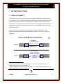
1
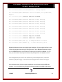
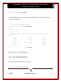
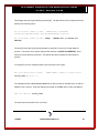
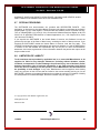
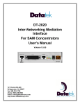
TM INSTALLATION AND ADMINISTRATION GUIDE FOR AIX ® RELEASE 1.0.22 379 Campus Drive, Suite 100 Somerset, NJ 08873 fax: 732.667.1091 phone: 732.667.1080 email: [email protected] http://www.datatekcorp.com IP-CommKit Installation and Administration Guide for AIX – Release 1.0.22 TABLE OF CONTENTS 1 INTRODUCTION .............................................................................................4 1.1 What is IP-CommKit? .....................................................................................4 2 DOCUMENTATION.........................................................................................5 3 INSTALLATION AND CONFIGURATION ......................................................6 3.1 Overview .........................................................................................................6 3.2 IP Addresses...................................................................................................7 3.3 UTM Installation..............................................................................................8 3.4 BNS Node Configuration..............................................................................11 3.5 Software Installation ....................................................................................14 3.5.1 Prerequisites............................................................................................................ 14 3.5.2 Removing CommKit Host Interface Software ...................................................... 15 3.5.3 Installing IP-CommKit Software............................................................................. 15 3.5.4 Registration ............................................................................................................. 17 3.6 Customize the Control Tables .....................................................................20 3.6.1 dkiptab...................................................................................................................... 20 3.6.2 dkitrc and dkitcfg .................................................................................................... 20 3.6.3 dksrvtab ................................................................................................................... 20 4 CONTROL TABLES .....................................................................................22 5 ADMINISTRATION .......................................................................................23 5.1 Files That Grow ............................................................................................23 5.2 dkitrc Script File ..........................................................................................23 5.3 Special Device Files .....................................................................................23 5.4 Printer Administration..................................................................................23 6 TROUBLESHOOTING ..................................................................................24 6.1 Overview .......................................................................................................24 6.2 Procedures....................................................................................................24 11/28/05 Datatek Applications Inc. 2 IP-CommKit Installation and Administration Guide for AIX – Release 1.0.22 6.2.1 Check that the UTM is in service ........................................................................... 24 6.2.2 Check that the CPM is in service........................................................................... 25 6.2.3 Check the Mode Switch on the UTM ..................................................................... 27 6.2.4 Ping the UTM from the host ................................................................................... 28 6.2.5 Check /var/opt/dk/log/dkipdlog.............................................................................. 28 6.2.6 Check /var/opt/dk/log/dkdaemonlog ..................................................................... 30 6.2.7 Check /var/opt/dk/dksrvlog .................................................................................... 32 6.3 Stopping and Starting ..................................................................................35 7 COMPATIBILITY...........................................................................................37 8 MANUAL PAGES .........................................................................................38 9 END-USER LICENSE AGREEMENT FOR SOFTWARE .............................39 9.1 SOFTWARE LICENSE ..................................................................................39 9.2 INTELLECTUAL PROPERTY RIGHTS..........................................................39 9.3 SOFTWARE SUPPORT.................................................................................40 9.4 EXPORT RESTRICTIONS .............................................................................40 9.5 LIMITED WARRANTY ...................................................................................40 9.6 NO OTHER WARRANTIES ...........................................................................40 9.7 SPECIAL PROVISIONS.................................................................................41 9.8 LIMITATION OF LIABILITY ...........................................................................41 11/28/05 Datatek Applications Inc. 3 IP-CommKit Installation and Administration Guide for AIX – Release 1.0.22 1 INTRODUCTION 1.1 WHAT IS IP-COMMKIT? IP-CommKit is a new twist on the CommKit Host Interface for BNS-2000 and BNS-2000 VCS (a.k.a. Datakit II VCS). Where the CommKit Host Interface uses a fiber optic cable to connect the host computer to the BNS node, IP-CommKit uses a 10Base-T LAN. Instead of a fiber interface card in the host computer, IP-CommKit uses the host’s standard LAN interface card. In the BNS node, use of IP-CommKit requires replacement of the CPM Module with a Universal Trunk Module (UTM). All of these changes are invisible to the host applications and the BNS network. Host applications and CommKit features behave identically. There is no need to recompile your applications. H o s t a n d N o d e In te rfa c e s C om m K i t H os t In t er fa c e E FO R E... . .. B EBFO RE OS H o st F IBE R C om pu te r M O D U LE F IBE R O P T IC CA B LE L IMIT E D DIS T A NC E S E P A R AT IO N B NS - 2 0 0 0 C PM or HS B NS - 2 0 0 0 V CS IP -C o m m K it H os t In t er fa c e 1 0 /1 0 0 Ba s e T 1 0 /1 0 0 Ba s e T F TE R .. . A AFT E R... S T AN D AR D OS H o st L AN C om pu te r M O D U LE IP U TM B NS - 2 0 0 0 or B NS - 2 0 0 0 V CS A NY W HE R E 11 IP-CommKit is a trademark of Lucent Technologies, Inc., licensed to Datatek Applications, Inc., a company independent of Lucent Technologies, Inc. Datakit is a registered trademark of Lucent Technologies, Inc., licensed to Datatek Applications, Inc., a company independent of Lucent Technologies, Inc. 11/28/05 Datatek Applications Inc. 4 IP-CommKit Installation and Administration Guide for AIX – Release 1.0.22 2 D O C U M E N T AT I O N Since IP-CommKit behaves like a CommKit Host Interface, you can use the CommKit Host Interface documentation to find answers to most questions. Specifically, use the CommKit Host Interface for NCR PCI Computers Installation and Administration Guide. This document follows the same general outline, i.e., it has the same major sections in the same order. Where there are changes or additions for IP-CommKit, they are described in the appropriate section of this document. While NCR computers running MP-RAS are very different from IBM computers running AIX releases, IP-CommKit is built from source code that was ported from the release of the CommKit Host Interface that ran on NCR computers. As a result, much of the information in the CommKit Host Interface for NCR PCI Computers Installation and Administration Guide applies to IP-CommKit running on IBM computers. AIX is a registered trademark of IBM. 11/28/05 Datatek Applications Inc. 5 IP-CommKit Installation and Administration Guide for AIX – Release 1.0.22 3 I N S T A L L AT I O N A N D C O N F I G U R AT I O N 3.1 OVERVIEW This section describes the procedures for connecting a host computer to a Lucent Technologies BNS-2000 or BNS-2000 VCS network using IP-CommKit. This section supercedes the Installation and Configuration section of the CommKit Host Interface for NCR PCI Computers Installation and Administration Guide. This section references procedures in the UTM User’s Manual. Have it handy before you begin. This section assumes that your host computer is already connected to a LAN. If it’s not, you should follow the procedures supplied with your computer for connecting it to a LAN. Installation and configuration of IP-CommKit consists of the following steps: • Obtain an IP address for the UTM and determine the appropriate subnet mask. Also determine the host IP address and, if needed, a gateway IP address. • Install the UTM and I/O distribution board in the BNS node. • Configure the UTM through its console port. • Configure the UTM in the BNS node’s controller database. • Install the IP-CommKit software on the host computer. • Register the IP-CommKit software. • Customize the dkiptab and, if needed, dkitcfg and the other control tables. The following sections describe each step in detail. 11/28/05 Datatek Applications Inc. 6 IP-CommKit Installation and Administration Guide for AIX – Release 1.0.22 3.2 IP ADDRESSES This section assumes a basic knowledge of IP networks. If you don’t have this knowledge, we recommend that you learn a little about them. We recommend Internetworking with TCP/IP, by Douglas E. Comer. Otherwise, enlist the help of your IP network administrator. Each UTM module requires an IP address, as does the host computer. You should obtain IP addresses for the UTM modules from your IP network administrator. This document assumes that the host computer is already connected to a LAN, and thus already has an IP address assigned to it. If your host connects to several LANs, it will have several IP addresses assigned to it, one for each LAN. You should find out the addresses assigned to the LAN that the host will use for communicating with the UTM. You need the host’s IP addresses in numeric form for configuring the UTM. To obtain this, enter the following command on the host computer: $ ifconfig -a The command should produce output similar to the following: lo0: flags=4049<UP,LOOPBACK,RUNNING,MULTICAST> mtu 8232 inet 127.0.0.1 netmask ff000000 le0: flags=4043<UP,BROADCAST,RUNNING,MULTICAST> mtu 1500 inet 135.17.59.166 netmask ffffff00 broadcast 135.17.59.255 In this example, the host has one LAN interface labeled le0. The inet field in the report shows that the IP address assigned to le0 is 135.17.59.166. To configure the UTM, you also need the subnet mask for the IP subnets to which it attaches. Most often, an IP subnet corresponds to a LAN segment. For example, all interfaces attached to 11/28/05 Datatek Applications Inc. 7 IP-CommKit Installation and Administration Guide for AIX – Release 1.0.22 the same 10Base-T hub are on the same LAN segment, and almost always have the same subnet mask. If the host and UTM connect to the same subnet, then you can find out the subnet mask from the output of the ifconfig command. In the previous example, the netmask field in the report shows that the subnet mask assigned to le0 is ffffff00. The subnet mask reported by ifconfig can’t be used directly to configure the UTM. The value ffffff00 is an 8-digit hexadecimal representation of a 32-bit mask. Unfortunately, the UTM expects this value in the Internet dot representation. To perform the conversion, divide the 8-digit value into four 2-digit fields, and convert each field to decimal. Concatenate the four decimal fields, placing a “.” (dot) between field. For example, ffffff00 converts to 255.255.255.0. If the host and UTM do not attach to the same subnet, your IP network administrator must provide you with an appropriate subnet mask for the UTM. In addition, the administrator must provide you with the IP address of a gateway router. This gateway must reside on the same subnet as the UTM, and must know how to route packets from the UTM to the host computer. Again, you need the gateway address in numeric form. 3.3 UTM INSTALLATION Consult the UTM User’s Manual, Section 3, for instructions on how to install the UTM and I/O distribution board in the BNS node. After you have installed the UTM and I/O distribution board in the BNS node, you must configure the UTM. The initial configuration of the UTM must be done through its console port. You can access the UTM console port in a variety of ways. For example, you can connect a “dumb” terminal directly to the console port on the I/O distribution board. You can also connect the console port into the BNS network through a SAM or TY module, and then access the console through a terminal or host that is connected to the network. Section 3 of the UTM User’s Manual shows how to make connections to the UTM’s console port. 11/28/05 Datatek Applications Inc. 8 IP-CommKit Installation and Administration Guide for AIX – Release 1.0.22 To configure the UTM, you need an IP address and subnet mask that you will assign to the UTM, as well as the IP address assigned to the host LAN interface. If the UTM and host are not on the same subnet, you will also need the IP address of a gateway that can forward packets from the UTM to the host. Enter the following commands on the UTM console port. <TRK-UNIV> login passwd=initial <TRK-UNIV> rm <TRK-UNIV> trk type=IPDSU <TRK-UNIV> trk modtype=CPM <TRK-UNIV> lo ipaddr=utm_ip_address submask=utm_subnet_mask <TRK-UNIV> ga ipaddr=gateway_ip_address <TRK-UNIV> trk dest=host_ip_address Here the IP addresses and subnet mask are shown in bold Italics. You would replace these names with numbers when you enter the commands. Enter the following command to check the configuration: 11/28/05 Datatek Applications Inc. 9 IP-CommKit Installation and Administration Guide for AIX – Release 1.0.22 <TRK-UNIV> vfy mod The output should be similar to the report below. Current Configuration: DK Board Type ==> TN1009 (CPM-HS) w/Serial# 136. Service State ==> Out of Service. Operating Mode ==> Simplex. Trunk Type ==> IP-DSU Compatible Trunk on 10BaseT Network Port. IP-DSU Loopback Status ==> Loopbacks are not enabled. IP-DSU Data Encryption Status ==> Disabled. Actual IP-DSU Service State ==> Not Connected. Local MAC Address ==> 0.19.5.84.49.56 Local IP Address ==> utm_ip_address Subnet Mask ==> subnet_mask Gateway IP Address ==> gateway_ip_address IP-DSU Destination IP Address ==> host_ip_address SNMP Trap Manager ==> Not defined. Check the address and subnet mask fields that you entered. If they are correct, enter the following command to restore the UTM to service. <TRK-UNIV> rs 11/28/05 Datatek Applications Inc. 10 IP-CommKit Installation and Administration Guide for AIX – Release 1.0.22 The UTM has many useful console commands that are not described here. See section 4 of the UTM User’s Manual for a complete description. Once you have done the initial configuration of the UTM through the console port, you can access all console commands through the LAN port via telnet. For example, you should be able to telnet to the UTM from the host on which you installed the IP-CommKit software. 3.4 BNS NODE CONFIGURATION If you are upgrading a CPM-HS module to a UTM, you don’t need to make any changes to the BNS node configuration. You can simply remove the CPM-HS module and its I/O distribution board, and install the UTM and its I/O distribution board in the same slot. The UTM appears as a CPM-HS module to the controller in the BNS node. If this is a new installation, you must configure the UTM in the BNS node’s controller database. The following procedure describes a simple configuration. It consists of entering a group, an address and a cpm in the controller database. Before you begin, pick a name that you will use as this host’s address in the BNS network. In configurations using a single dkserver, it’s convenient to make this address and the group name the same as the host’s nodename. By default, dkserver announces itself to the BNS node by the host’s nodename. To determine this name, enter the following command on the host: $ uname -n This prints the host’s nodename. Note that the uname(1M) command with no flags is equivalent to uname -s. This prints the system name, which can be different from the nodename. If you find this confusing, you can use the setuname(1M) command to make the system name and node name the same. 11/28/05 Datatek Applications Inc. 11 IP-CommKit Installation and Administration Guide for AIX – Release 1.0.22 If you want to use a name that’s different from the host’s nodename, you must modify the dkitcfg file. See section 3.6.2. Now, enter a group. A group binds together a collection of like modules under one name. In this simple example, there is only one UTM, so the group has only one member. In more complex configurations, you can put up to eight UTMs in one group and distribute incoming calls between these modules using round robin service. The following dialogue shows the procedure for entering a group on the BNS node console. Text that you type exactly is shown in bold, and text that you modify for your installation is shown in bold italics. <Enter> and <Delete> refer to the enter and delete keys on your keyboard. CC0> enter group GROUP [up to 8 chars]: nodename TYPE [local, trunk: +(local)]: local DIRECTION [originate, receive, 2way]: 2way DEVICE OR HOST [up to 8 chars: +(standard)]: <Enter> PASSWORD [up to 8 chars, none: +(none)]: <Enter> ROUND ROBIN SERVICE [per_port, per_module, none: +(none)]: <Enter> GROUP [up to 8 chars]: <Delete> Next, enter an address. An address is bound to one or more groups. In this simple example, there is one group, with one UTM in the group. We use the same name for the group and address in this example, although it’s not required. CC0> enter address 11/28/05 Datatek Applications Inc. 12 IP-CommKit Installation and Administration Guide for AIX – Release 1.0.22 LEVEL [network, area, exchange, local, speedcall: +(local)]: <Enter> TYPE [numeric, mnemonic, both: +(mnemonic)]: <Enter> MNEMONIC ADDRESS [up to 8 chars]: nodename PAD SUPPORT [yes, no: +(no)]: <Enter> DIRECTORY ENTRY [up to 30 chars double quoted, none: +(none)]: "appropriate description of host" GROUP(S) [up to 4 groups separated by commas, none: +(none)]: nodename ORIGINATING GROUP NAME SECURITY PATTERN(S) [comma-separated pattern list, same_as, none: +(none)]: <Enter> INITIAL SERVICE STATE [in, out: +(out)]: in LEVEL [network, area, exchange, local, speedcall: +(local)]: <Delete> Next, enter the cpm. In reality, the cpm is a UTM, but the BNS controller can’t tell the difference. In the dialog below, you must use values for mod_address and num_channels that are correct for your configuration. Use the slot number where you installed the UTM for the mod_address. By default, dkdaemon (1M) sets the number of channels per UTM to 64, so use this value for num_channels. If you want to use more channels, you must modify the dkitcfg file. See section 3.6.2. CC0> enter cpm MODULE ADDRESS: mod_address COMMENT [up to 60 chars double quoted, or none: +(none)]: "appropriate comment" 11/28/05 Datatek Applications Inc. 13 IP-CommKit Installation and Administration Guide for AIX – Release 1.0.22 HARDWARE TYPE [422, hs: +(hs)]: <Enter> NUMBER OF CHANNELS [3-512: +(32)]: num_channels CALL SCREENING PROFILE ID [up to 8 chars, none: +(none)]: <Enter> CONNECT-TIME BILLING [on, off: +(off)]: <Enter> SINGLE OR MULTIPLE GROUPS [single, multiple: +(single)]: <Enter> GROUP [up to 8 chars]: nodename ENDPOINT NUMBER OR RANGE [0000-9999, none: +(none)]: <Enter> MODULE ADDRESS: <Delete> Finally, restore the cpm to service. CC0> restore cpm MODULE ADDRESS: mod_address 3.5 3.5.1 SOFTWARE INSTALLATION PREREQUISITES Before installing any software on your computer, verify that it is running a release of its operating system that supports IP-CommKit. See the IP-CommKit Release Notes for a list of supported operating system releases. Do not attempt to install the IP-CommKit software if your computer is running an operating system release that is not supported. 11/28/05 Datatek Applications Inc. 14 IP-CommKit Installation and Administration Guide for AIX – Release 1.0.22 3.5.2 REMOVING COMMKIT HOST INTERFACE SOFTWARE If you are upgrading a computer from the CommKit Host Interface to IP-CommKit, you must remove the CommKit Host Interface software before installing the IP-CommKit. For IBM computers, CBM of America supplies the host interface software under the name Powerkit®. Consult the documentation provided by CBM of America for instructions on removing the Powerkit software package. 3.5.3 INSTALLING IP-COMMKIT SOFTWARE Use the following procedure to install the IP-CommKit software. The IP-CommKit software is delivered electronically or on CD as multiple files in tape archive (tar) format. The file is named ipckax.tar or ipckax32.tar. First, log in as root on the host where you wish to install the software. If you have a CD, enter the following commands to mount it and expand the tar file: 11/28/05 Datatek Applications Inc. 15 IP-CommKit Installation and Administration Guide for AIX – Release 1.0.22 # mkdir /cdrom # mount -r -v cdrfs /dev/cd0 /cdrom # mkdir /tmp/ipcommkit # cd /tmp/ipcommkit Retrieve the .tar file from the CD: For AIX R4.3 hosts: # tar xf /cdrom/aix_4_3/ipckax.tar For AIX R5.2 hosts running a 32-bit kernel: # tar xf /cdrom/aix_5_2/ipckax32.tar For all AIX hosts: # umount /cdrom If you received the tar file electronically, the procedure is similar. Copy the tar file to the machine on which you are installing the software. For example, suppose that you copied the tar file to /tmp. To expand the tar file, enter the following commands: # mkdir /tmp/ipcommkit # cd /tmp/ipcommkit For AIX R4.3 hosts # tar xf /tmp/ipckax.tar For AIX R5.2 32 bit hosts: # tar xf /tmp/ipckax32.tar 11/28/05 Datatek Applications Inc. 16 IP-CommKit Installation and Administration Guide for AIX – Release 1.0.22 To install the software, enter the following command: # installp -a -d /tmp/ipcommkit ipcommkit If you want to install the IP-CommKit manual pages, enter one more command: # installp -a -d /tmp/ipcommkit ipcommkitShare Your host is now configured to start the IP-CommKit software automatically at boot time. You can reboot your host, but you will need to register your copy of the software and configure your control tables before you can use IP-CommKit. Refer to those procedures later in this document. To reboot your host, enter the following commands: # cd / # shutdown -F -r 3.5.4 REGISTRATION Starting with revision 1.0.12, the IP-CommKit software is copy-protected. You must obtain a software key and register your copy of the software before you can use IP-CommKit. Here is how the registration process works: When you purchase IP-CommKit, we provide you with a software certificate number. For example, here is the software certificate number for the IP-CommKit software running on one of Datatek’s development machines: 20AX523-000603-5FAH 11/28/05 Datatek Applications Inc. 17 IP-CommKit Installation and Administration Guide for AIX – Release 1.0.22 If you received your software on a CD, the software certificate number is printed on the label. If the software was delivered electronically, the software certificate number is included in the e-mail message. In either case, you must save the software certificate number since it serves as your proof of purchase. After installing the IP-CommKit software on your host computer, contact us to obtain a software key. To generate your software key, we need your software certificate number and the nodename of the host on which the software is installed. To determine the nodename, enter the following command on the host: $ uname -n This prints the host's nodename. The best way to contact us is to send an e-mail message to the following address: [email protected] In addition to your software certificate number and your host's nodename, please include your name, your company's name, your e-mail address and telephone number. Also include the revision number of the IP-CommKit software. This will help us to contact you when maintenance releases are available. This documentation applies only to revisions starting with 1.0.12.0. Datatek will send you a reply with a software key that is generated from your software certificate number and your host's nodename. For example, here is the software key for Datatek’s development machine: 11/28/05 Datatek Applications Inc. 18 IP-CommKit Installation and Administration Guide for AIX – Release 1.0.22 AT422-2222-MS5A-YVE3 While e-mail is the best way to obtain a software key, we can also give you one over the telephone. Here are our names and numbers: Dan Conklin Jacquie Kupper Senior Product Manager Senior Release Coordinator 732 667-1080 ext. 162 732 667-1080 ext. 149 With the software certificate number and software key, you can register the IP-CommKit software on your host. Log in a root, and run the following command: $ /usr/sbin/dkregister The command will prompt you for the software certificate number and the software key, then validate the values that you enter. If they are correct, it will save the registration information on the host's disk. You will need to register your IP-CommKit software on this host again when you install maintenance releases. It’s now a good time to customize your control tables. (If you had just re-registered your IPCommKit software and do not need to customize your control tables, start IP-CommKit again. See section 6.3 for details.) 11/28/05 Datatek Applications Inc. 19 IP-CommKit Installation and Administration Guide for AIX – Release 1.0.22 3.6 3.6.1 CUSTOMIZE THE CONTROL TABLES DKIPTAB (IP-CommKit must be stopped before you update this table. See section 6.3 for details.) The dkiptab is a new control file for IP-CommKit that tells the IP-CommKit software the IP addresses assigned to the UTM and the host LAN interfaces. Even if you are upgrading a computer from the CommKit Host Interface to IP-CommKit, you still must enter the dkiptab before IP-CommKit will operate. While the installation scripts create a dkiptab file in the appropriate directory, it contains only comments. Fortunately, the dkiptab is very easy to enter with your favorite text editor. See the manual page (dkiptab(4)) for the file format and examples. 3.6.2 DKITRC AND DKITCFG /etc/dkitrc is a shell script that starts and stops the IP-CommKit software on the host computer. The installation scripts configure inittab(4) so that /etc/dkitrc is run automatically when the run level of the host computer changes, i.e., at startup and shutdown. Specifically, the IP-CommKit software starts when the host enters run level 2, and stops when the host enters either run level 0 or 1: The operation of dkitrc is controlled by /etc/opt/dk/dkitcfg. The dkitrc and dkitcfg scripts for IP-CommKit are different from the scripts used in some versions of CommKit Host Interface software. If you are upgrading a computer from the CommKit Host Interface to IP-CommKit, and you customized the configuration in dkitrc script, you will need to customize the dkitcfg script supplied with the IP-CommKit software. The most common reason for customizing the dkitcfg script is to change the number of channels available per interface from the default value of 64. The dkitcfg script itself contains instructions for making modifications. It should not be necessary to make any modifications to the dkitrc script. 3.6.3 DKSRVTAB If you are upgrading your computer from the CommKit Host Interface to IP-CommKit, it’s likely that the tables used by dkserver [see srvtab(4)] have already been customized. No changes to these tables are needed to use IP-CommKit. 11/28/05 Datatek Applications Inc. 20 IP-CommKit Installation and Administration Guide for AIX – Release 1.0.22 If you are installing IP-CommKit on a computer that has never run the CommKit Host Interface software, the installation script installs a default set of server tables. /usr/sbin/dkcust is a script that can automatically customize these default tables. To use dkcust, you should know the area and exchange assigned to the BNS node in which you install the UTM. This information can be obtained by entering the verify node command on the BNS node console. Ask your BNS node administrator, if you need assistance. To use dkcust, simply run it and answer the questions. 11/28/05 Datatek Applications Inc. 21 IP-CommKit Installation and Administration Guide for AIX – Release 1.0.22 4 C O N T R O L TA B L E S The control tables used for the CommKit Host Interface are identical to those used for IPCommKit. Refer to Control Tables section of the CommKit Host Interface for NCR PCI Computers Installation and Administration Guide for a detailed description of the control tables. IP-CommKit has one additional control table, dkiptab. This file is read by dkipd when it starts to find the IP addresses assigned to the UTM and host LAN interfaces. See the manual page (dkiptab(4)) for the file format and examples. 11/28/05 Datatek Applications Inc. 22 IP-CommKit Installation and Administration Guide for AIX – Release 1.0.22 5 A D M I N I S T R AT I O N All of the topics discussed in the Administration section of the CommKit Host Interface for NCR PCI Computers Installation and Administration Guide apply to IP-CommKit as well. There are few minor changes and additions that are noted below: 5.1 FILES THAT GROW dkipd creates a log file in /var/opt/dk/log/dkipdlog. This file will grow continuously, although at a very slow rate compared to other log files, and should be cleaned out periodically by the system administrator. 5.2 DKITRC SCRIPT FILE In addition to starting dkdaemon and dkserver, dkitrc starts dkipd. 5.3 SPECIAL DEVICE FILES The minor devices for the diagnostic channels, /dev/dk/diag0, etc., are not created for IPCommKit. These devices were used for managing hardware diagnostics for the fiber interface board that is part of the CommKit Host Interface. IP-CommKit uses the LAN interface on your host computer, and thus relies on the hardware diagnostics supplied with the LAN interface. IP-CommKit has one additional special device file, /dev/dk/dkip, tied to minor device number 16384. This device is used exclusively by dkipd to initialize the driver when it starts up. 5.4 PRINTER ADMINISTRATION There are several figures in this section that show fibers connecting hosts to CPM-HS boards in the switches. With IP-CommKit, the hosts are connected to UTMs in the switches through IP networks. 11/28/05 Datatek Applications Inc. 23 IP-CommKit Installation and Administration Guide for AIX – Release 1.0.22 6 TROUBLESHOOTING 6.1 OVERVIEW This section describes troubleshooting procedures for IP-CommKit. It supercedes the Troubleshooting section of the CommKit Host Interface for NCR PCI Computers Installation and Administration Guide. 6.2 PROCEDURES You are most likely to have difficulty with IP-CommKit right after installation. The following sections describe procedures for troubleshooting the most common problems encountered after installation. If you are having difficulty, start with the first procedure and work towards the end. Resist the temptation to skip procedures that seem obvious. 6.2.1 CHECK THAT THE UTM IS IN SERVICE Enter the following command on the UTM console port: <TRK-UNIV> vfy mod The output should be similar to the report below. Current Configuration: DK Board Type ==> TN1009 (CPM-HS) w/Serial# 136. Service State ==> In Service. Operating Mode ==> Simplex. Trunk Type ==> IP-DSU Compatible Trunk on 10BaseT Network Port. 11/28/05 Datatek Applications Inc. 24 IP-CommKit Installation and Administration Guide for AIX – Release 1.0.22 IP-DSU Loopback Status ==> Loopbacks are not enabled. IP-DSU Data Encryption Status ==> Disabled. Actual IP-DSU Service State ==> Not Connected. Local MAC Address ==> 0.19.5.84.49.56 Local IP Address ==> utm_ip_address Subnet Mask ==> subnet_mask Gateway IP Address ==> gateway_ip_address IP-DSU Destination IP Address ==> host_ip_address SNMP Trap Manager ==> Not defined. Specifically, check that the Service State is In Service. If it’s not, enter the following command on the UTM console: <TRK-UNIV> rs 6.2.2 CHECK THAT THE CPM IS IN SERVICE Enter the following command on the BNS node console: CC0> dstat mod mod_address In this command, mod_address is the slot number where you installed the UTM. The output should be similar to the report below: 00-12-18 13:43:46 NODE=node_name 11/28/05 Datatek Applications Inc. 25 IP-CommKit Installation and Administration Guide for AIX – Release 1.0.22 M dstat module mod_address ****************************** MODULE 19 ****************************** MODULE TYPE SERVICE STATE HARDWARE ERROR COUNT SERIAL NUMBER cpmhs in service 1 136 LAST HARDWARE ALARM none ONLINE yes yes ENABLED CABLE connected AVAIL yes Specifically, check that the SERVICE STATE is in service. If it’s not, enter the following command on the node console: CC0> rs cpm mod_address 11/28/05 Datatek Applications Inc. 26 IP-CommKit Installation and Administration Guide for AIX – Release 1.0.22 6.2.3 CHECK THE MODE SWITCH ON THE UTM Verify the Mode switch on the faceplate of the UTM module is in the enabl position. The Mode switch supports three positions: Enabl, Diag and Disab. The Mode switch must be in the Enabl position for the UTM to function properly. Reset Mode Enabl Switch Diag Disab Red Fault Yellow Off Line Green On Line Datatek DSPQOOYAXX TN 2524 UTM 11/28/05 Datatek Applications Inc. 27 IP-CommKit Installation and Administration Guide for AIX – Release 1.0.22 6.2.4 PING THE UTM FROM THE HOST On the host computer, enter the following command: $ ping utm_ip_address In this command, utm_ip_address is the IP address that you assigned to the UTM module. The output should be similar to the report below: 64 bytes from utm_ip_address: icmp_seq=0 ttl=254 time=0 ms 64 bytes from utm_ip_address: icmp_seq=1 ttl=254 time=1 ms 64 bytes from utm_ip_address: icmp_seq=2 ttl=254 time=0 ms 64 bytes from utm_ip_address: icmp_seq=3 ttl=254 time=0 ms The ping command will continue to print until you kill it. If you don't get this output, check that you are using the correct UTM IP address. If you are, you should enlist the aid of you IP network administrator. Don’t proceed until you can ping the UTM from the host. 6.2.5 CHECK /VAR/OPT/DK/LOG/DKIPDLOG Enter the following command on the host computer: $ tail /var/opt/dk/log/dkipdlog 11/28/05 Datatek Applications Inc. 28 IP-CommKit Installation and Administration Guide for AIX – Release 1.0.22 This displays the end of the log file created by dkipd(1M). The last two lines of the output should be similar to the report below: Dec 18 12:08:54 (8626) Connectivity from host_ip_address to utm_ip_address established Dec 18 12:09:19 (8626) UTM module utm_ip_address restored to service Here, the host_ip_address is the IP address assigned to the host computer, and the utm_ip_address is the IP address assigned to the UTM. Note that dkipd will use the name associated with the address, if possible. If your host connects to several UTMs, you should see these two messages repeated for each UTM IP address. If you see the first line, “Connectivity from …”, but not the second, “UTM module …”, it indicates that the CPM is out of service. Go back to the procedure for checking that the CPM is in service. If the output on your host is different, compare it to the following output examples that are associated with common problems. /usr/sbin/dkipd: Error in configuration file "/etc/opt/dk/dkiptab" Line 38: 0 dino 135.17..59.203 Can't resolve address: 135.17..59.203 This output is typical of an error in dkiptab, the configuration file for dkipd. You may have forgotten to customize the file for you application, or you may have made a typing error. In the output above, there was an error typing in the IP address of the UTM module. Note that the error message indicates the line number where the error was detected. 11/28/05 Datatek Applications Inc. 29 IP-CommKit Installation and Administration Guide for AIX – Release 1.0.22 Dec 18 14:26:38 (8810) Received keep-alive message from unknown address: 135.17.59.203 This output is typical when the UTM IP address you configured in dkiptab does not match the UTM IP address you configured through the UTM console. If the messages that you see don’t look similar to any of the examples above, consult the dkipd(1M) manual page. This describes all messages that are written to the log file. The primary responsibility for dkipd is to establish communications with the UTM. You can confirm that dkipd and the UTM have established communications by issuing the vfy command on the UTM console. The report should contain the following line: Actual IP-DSU Service State ==> Peer Connectivity Established. 6.2.6 CHECK /VAR/OPT/DK/LOG/DKDAEMONLOG Enter the following command on the host computer: # tail -17 /var/opt/dk/log/dkdaemonlog This displays the log file created by dkdaemon(1M). The output should look similar to the following report: Dec 18 14:55:09 (8866) /usr/sbin/dkdaemon : Started, Log Level = 5 Dec 18 14:55:09 (8867) acct_start: Accounting Disabled 11/28/05 Datatek Applications Inc. 30 IP-CommKit Installation and Administration Guide for AIX – Release 1.0.22 Dec 18 14:55:09 (8867) /usr/sbin/dkdaemon : Startup Complete Dec 18 14:55:09 (8867) dkhsstart: Unit 0: 512 Chans, Ver 4, Rbuf 1024, NurpB 4 Dec 18 14:55:09 (8867) startstr: dkhs Unit 0 ACTIVE Dec 18 14:55:09 (8867) startstr: dkhs Unit 1 Down, Retrying Dec 18 14:55:09 (8867) startstr: dkhs Unit 2 Down, Retrying Dec 18 14:55:09 (8867) startstr: dkhs Unit 3 Down, Retrying Dec 18 14:55:09 (8867) startstr: dkhs Unit 4 Down, Retrying Dec 18 14:55:09 (8867) startstr: dkhs Unit 5 Down, Retrying Dec 18 14:55:09 (8867) startstr: dkhs Unit 6 Down, Retrying Dec 18 14:55:09 (8867) startstr: dkhs Unit 7 Down, Retrying Dec 18 14:55:09 (8867) startstr: dknp Unit 0 ACTIVE Dec 18 14:55:09 (8867) startstr: dkxmx Unit 0 ACTIVE Dec 18 14:55:09 (8867) LOG: (0, 0) dkxqt mux driver is active Dec 18 14:55:11 (8867) SERVER: (0, 2) "dino" Started by UID 0 By default, dkdaemon tries to start all eight logical interfaces. Only one logical interface is used on the host computer where this log file was generated. This is Unit 0, and dkdaemon reports that it is ACTIVE. dkdaemon reports that the remaining logical interfaces are Down. On your host, you should check that all logical interfaces that you specified in the dkiptab are active. If the messages that you see don’t look similar to any of the examples above, consult the dkdaemon (1M) manual page. This describes all messages that are written to the log file. Once dkdaemon starts, the host computer establishes communications with the BNS node controller. You can confirm this by running the following command on the BNS node console: 11/28/05 Datatek Applications Inc. 31 IP-CommKit Installation and Administration Guide for AIX – Release 1.0.22 CC0> disp conn mod mod_address Here, mod_address is the slot number where you installed the UTM. The output should look similar to the report below: 00-12-19 17:46:20 NODE=node_name M display connections mod mod_address MODULE: 19 --------------CH/PT CU/TM GROUP PKT CNT STATE TO MOD CH/PT CU/TM GROUP PKT CNT BOARD (+ = PDD BOARD CS/LCH or PVC, CS/LCH PT/LCH # = RRC) PT/LCH PT/DLCI 1 PT/DLCI **** 295 ACTIVE Note that channel 1 is in the ACTIVE state. 6.2.7 CHECK /VAR/OPT/DK/DKSRVLOG Enter the following command on the host computer $ tail /var/opt/dk/log/dksrvlog 11/28/05 Datatek Applications Inc. 32 IP-CommKit Installation and Administration Guide for AIX – Release 1.0.22 This displays the log file generated by dkserver(1M). The last few lines of the output should look similar to the following report: Dec 18 14:55:11 (8893) [0.000] SERVER dino is INITING files=(/etc/opt/dk/srvtab /etc/opt/dk/dkuidtab) loglvl=6 Dec 18 14:55:11 (8893) [0.000] dkmgr : SERVER dino is ACTIVE and SERVING The host file where this log file was generated is named dino, and it runs a single dkserver process. The last line of the log file indicates that dkserver is ACTIVE and SERVING. Some hosts run several dkserver processes. The last line should be repeated for each dkserver process. You might see an error message similar to the one below in the log file: Dec 19 17:00:59 (515) [0.000] ERROR dkmgr: Unable to create server server_name dk_errno = 3 The indicates that the address server_name has not been entered on the BNS node, or that the address is not in service. Enter the following command on the BNS node to check the address: CC0> ver addr all server_name The report should be similar to the one below: 11/28/05 Datatek Applications Inc. 33 IP-CommKit Installation and Administration Guide for AIX – Release 1.0.22 00-12-19 17:16:42 NODE=node_name M verify address all server_name MNEMONIC ADDRESS: server_name X.121 NANP ADDRESS: LEVEL: local SERVICE STATE: in PAD SUPPORT: no DIRECTORY: none SECURITY: none GROUP: group_name If the report indicates that the address has not been entered, enter it using the instructions in the BNS Node Configuration section of this document. If the report shows that the address is out of service, restore the address with the following command: CC0> res addr local server_name When dkserver starts, it tells the BNS node that it is ready to accept incoming calls. You can confirm this by entering the follow command on the BNS node console: CC0> disp conn mod mod_address 11/28/05 Datatek Applications Inc. 34 IP-CommKit Installation and Administration Guide for AIX – Release 1.0.22 The report should be similar to the one below: 00-12-19 17:46:20 NODE=node_name M display connections mod mod_address MODULE: 19 --------------CH/PT CU/TM GROUP PKT CNT STATE TO MOD CH/PT CU/TM GROUP PKT CNT BOARD (+ = PDD BOARD CS/LCH or PVC, CS/LCH PT/LCH # = RRC) PT/LCH PT/DLCI PT/DLCI 1 **** 2 group_name 295 89 ACTIVE SERVING Note that channel 2 is in the SERVING state. 6.3 STOPPING AND STARTING Some configuration changes require stopping and starting the IP-CommKit software to make the changes effective. Specifically, changes to /etc/opt/dk/dkiptab require stopping and starting. You can always do this by rebooting the host computer. However, this can be disruptive and time consuming. A more convenient method is to log in as root, then enter the follow commands: # sh /etc/dkitrc stop 11/28/05 Datatek Applications Inc. 35 IP-CommKit Installation and Administration Guide for AIX – Release 1.0.22 # sh /etc/dkitrc start 11/28/05 Datatek Applications Inc. 36 IP-CommKit Installation and Administration Guide for AIX – Release 1.0.22 7 C O M P AT I B I L I T Y This section of the CommKit Host Interface for NCR PCI Computers Installation and Administration Guide describes the differences between UNIX System V Release 3 (SVR3) and Release 4 (SVR4) versions. IP-CommKit for AIX was derived from the SRV4 version, so the information in this section also applies to IP-CommKit. However, it’s only useful if you are porting a CommKit Host Interface application that ran under SRV3 to IP-CommKit. UNIX is a registered trademark in the United States and other countries licensed exclusively through X/Open Company, Ltd. 11/28/05 Datatek Applications Inc. 37 IP-CommKit Installation and Administration Guide for AIX – Release 1.0.22 8 M AN U AL PA G E S Most of the manual pages for the CommKit Host Interface are identical to those for IP-CommKit. The following man pages have been eliminated: ATDIAG DKCFG DKDIAG DKMAP DKREGISTER DKUNLOCK DKVFY PCDIAG These pages described commands that were used for copy protection or fiber interface hardware configuration and diagnostics. These commands are not needed for IP-CommKit. The following manual pages have been added or revised for IP-CommKit DKIPD DKIPTAB DKITRC Use the man command to obtain copies of these pages. 11/28/05 Datatek Applications Inc. 38 IP-CommKit Installation and Administration Guide for AIX – Release 1.0.22 9 END-USER LICENSE AGREEMENT FOR SOFTWARE This License Agreement ("License") is a legal contract between you and the manufacturer ("Manufacturer") of the software product(s) you acquired identified as ("SOFTWARE"). The SOFTWARE may include printed materials that accompany the SOFTWARE. Any software provided along with the SOFTWARE that is associated with a separate end-user license agreement is licensed to you under the terms of that license agreement. By installing, copying, downloading, accessing or otherwise using the SOFTWARE, you agree to be bound by the terms of this LICENSE. If you do not agree to the terms of this LICENSE, Manufacturer is unwilling to license the SOFTWARE to you. In such event, you may not use or copy the SOFTWARE, and you should promptly contact Manufacturer for instructions on return of the unused product(s) for a refund. 9.1 SOFTWARE LICENSE You may only install and use one copy of the SOFTWARE on one host computer (unless otherwise licensed by Manufacturer). The SOFTWARE may not be installed, accessed, displayed, run, shared or used concurrently on or from different computers, including a workstation, terminal or other digital electronic device (“Devices”). Notwithstanding the foregoing and except as otherwise provided below, any number of Devices may access or otherwise utilize the services of the SOFTWARE. You may not reverse engineer, decompile, or disassemble the SOFTWARE, except and only to the extent that such activity is expressly permitted by applicable law notwithstanding this limitation. The SOFTWARE is licensed as a single product. Its component parts may not be separated for use on more than one host computer. You may not rent, lease or lend the SOFTWARE in any manner. You may permanently transfer all of your rights under this LICENSE provided you retain no copies, you transfer all of the SOFTWARE (including all component parts, the media and printed materials, any upgrades, this LICENSE and, if applicable, the Certificate(s) of Authenticity), and the recipient agrees to the terms of this LICENSE. If the SOFTWARE is an upgrade, any transfer must also include all prior versions of the SOFTWARE. Without prejudice to any other rights, Manufacturer may terminate this LICENSE if you fail to comply with the terms and conditions of this LICENSE. In such event, you must destroy all copies of the SOFTWARE and all of its component parts. 9.2 INTELLECTUAL PROPERTY RIGHTS The SOFTWARE is licensed, not sold to you. The SOFTWARE is protected by copyright laws and international copyright treaties, as well as other intellectual property laws and treaties. You may not copy the printed materials accompanying the SOFTWARE. All title and intellectual property rights in and to the content which may be accessed through use of the SOFTWARE is the property of the respective content owner and may be protected by applicable copyright or other intellectual property laws and treaties. This LICENSE grants you no rights to use such content. All rights not expressly granted under this LICENSE are reserved Manufacturer and its licensors (if any). 11/28/05 Datatek Applications Inc. 39 IP-CommKit Installation and Administration Guide for AIX – Release 1.0.22 9.3 SOFTWARE SUPPORT SOFTWARE support is provided by Manufacturer, or its affiliates or subsidiaries separate from the host computer on which it may be installed. SOFTWARE support is limited to the warranty period stated below unless either a separate contract has been consummated between you and the manufacturer or the manufacturer has agreed in writing at the time of purchase by you of the software to an extension of the warranty. Should you have any questions concerning this LICENSE, or if you desire to contact Manufacturer for any other reason, please refer to the address provided in the documentation for the SOFTWARE. 9.4 EXPORT RESTRICTIONS You agree that you will not export or re-export the SOFTWARE to any country, person, or entity subject to U.S. export restrictions. You specifically agree not to export or re-export the SOFTWARE: (i) to any country to which the U.S. has embargoed or restricted the export of goods or services, which as of March 1998 include, but are not necessarily limited to Cuba, Iran, Iraq, Libya, North Korea, Sudan and Syria, or to any national of any such country, wherever located, who intends to transmit or transport the products back to such country; (ii) to any person or entity who you know or have reason to know will utilize the SOFTWARE or portion thereof in the design, development or production of nuclear, chemical or biological weapons; or (iii) to any person or entity who has been prohibited from participating in U.S. export transactions by any federal agency of the U.S. government. 9.5 LIMITED WARRANTY Manufacturer warrants that (a) the SOFTWARE will perform substantially in accordance with the accompanying written materials for a period of ninety (90) days from the date of shipment from Datatek Applications, Inc. Software support is limited to the hours of 9 AM to 5 PM ET Monday through Friday excluding Datatek-observed holidays. Other coverage and extended warranty may be purchased at additional cost. Any implied warranties on the SOFTWARE are limited to ninety (90) days. Some states/jurisdictions do not allow limitations on duration of an implied warranty, so the above limitation may not apply to you. Manufacturer's and its suppliers' entire liability and your exclusive remedy shall be, at Manufacturer's option, either (a) return of the price paid, or (b) repair or replacement of the SOFTWARE that does not meet this Limited Warranty and which is returned to Manufacturer with a copy of your receipt. This Limited Warranty is void if failure of the SOFTWARE has resulted from accident, abuse, or misapplication. Any replacement SOFTWARE will be warranted for the remainder of the original warranty period or thirty (30) days, whichever is longer. 9.6 NO OTHER WARRANTIES TO THE MAXIMUM EXTENT PERMITTED BY APPLICABLE LAW, MANUFACTURER AND ITS SUPPLIERS DISCLAIM ALL OTHER WARRANTIES, EITHER EXPRESS OR IMPLIED, INCLUDING, BUT NOT LIMITED TO IMPLIED WARRANTIES OF MERCHANTABILITY, FITNESS FOR A PARTICULAR PURPOSE AND NONINFRINGEMENT, WITH REGARD TO THE SOFTWARE AND THE ACCOMPANYING WRITTEN MATERIALS. THIS LIMITED 11/28/05 Datatek Applications Inc. 40 IP-CommKit Installation and Administration Guide for AIX – Release 1.0.22 WARRANTY GIVES YOU SPECIFIC LEGAL RIGHTS. YOU MAY HAVE OTHERS, WHICH VARY FROM STATE/JURISDICTION TO STATE/JURISDICTION. 9.7 SPECIAL PROVISIONS The SOFTWARE and documentation are provided with RESTRICTED RIGHTS. Use, duplication, or disclosure by the United States Government is subject to restrictions as set forth in subparagraph (c)(1)(ii) of the Rights in Technical Data and Software clause at DFARS 252.2277013 or subparagraphs (c)(1) and (2) of the Commercial Software-Restricted Rights at 48 CFR 52.227-19, as applicable. Manufacturer is Datatek Applications, Inc., 379 Campus Drive, Suite 100, Somerset, NJ 08873. If you acquired the SOFTWARE in the United States of America, this Software License are governed by the laws of the State of New Jersey, excluding its choice of laws provisions. If you acquired the SOFTWARE outside the United States of America, local law may apply. This LICENSE constitutes the entire understanding and agreement between you and the Manufacturer in relation to the SOFTWARE and supersedes any and all prior or other communications, statements, documents, agreements or other information between the parties with respect to the subject matter hereof. 9.8 LIMITATION OF LIABILITY To the maximum extent permitted by applicable law, in no event shall Manufacturer or its suppliers be liable for any damages whatsoever (including without limitation, special, incidental, consequential, or indirect damages for personal injury, loss of business profits, business interruption, loss of business information, or any other pecuniary loss) arising out of the use of or inability to use this product, even if Manufacturer has been advised of the possibility of such damages. In any case, Manufacturer's and its suppliers' entire liability under any provision of this License shall be limited to the amount actually paid by you for the SOFTWARE. Because some states/jurisdictions do not allow the exclusion or limitation of liability for consequential or incidental damages, the above limitation may not apply to you. © Copyright 2001, 2006 Datatek Applications, Inc. All Rights Reserved Printed in USA 11/28/05 Datatek Applications Inc. 41