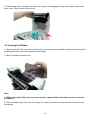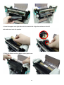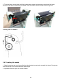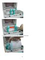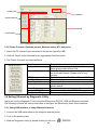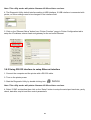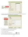
1
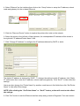
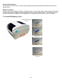
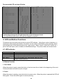
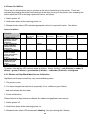
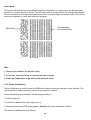
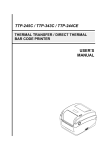
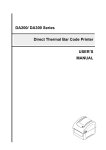
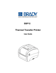
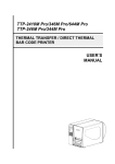
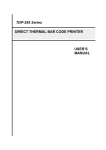
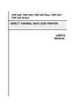
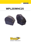
LabelStation
Model CN
THERMAL TRANSFER / DIRECT THERMAL BAR CODE PRINTER
USER MANUAL
1
Contents
1. Introduction (product & compliances) .......................................................................... 4
2. Operations Overview ...................................................................................................... 5
2.1 Unpacking and Inspection............................................................................................ 5
2.2 Printer Overview (exterior & interior views and SD card spec.)................................ 6
3. Setup ................................................................................................................................ 8
3.1 Setting Up the Printer ................................................................................................... 8
3.2 Open / Close the Top Cover ......................................................................................... 9
3.3 Loading the Ribbon....................................................................................................... 10
3.4 Loading the Media (label stock) ................................................................................... 12
3.4.2 External Label Roll Mount Installation (Optional).................................................... 15
3.4.3 Loading Media in Peel-off Mode (Option)................................................................. 16
3.4.4 Loading Media in Cutter Mode (Option) ................................................................... 18
3.5 Diagnostic Tool ............................................................................................................. 19
3.5.1 Start the Diagnostic Tool........................................................................................... 19
3.5.2 Printer Function (Calibrate sensor, Ethernet setup, RTC setup etc.) .................... 20
3.6 Setting Ethernet by Diagnostic Utility ......................................................................... 20
3.6.1 Using USB interface to setup Ethernet interface..................................................... 20
3.6.2 Using RS-232 interface to setup Ethernet interface ................................................ 21
3.6.3 Using Ethernet interface to setup Ethernet interface.............................................. 22
3.7 Install SD Memory Card ................................................................................................ 24
4. LED and Button Functions ............................................................................................. 25
4.1 LED indicator ................................................................................................................. 25
4.2 Button Function............................................................................................................. 25
4.3 Power on utilities (utilities available when switching printer on) ............................. 26
4.3.1 Ribbon and Gap/Black Mark Sensor Calibration ..................................................... 26
4.3.2 Gap/Black Mark Calibration, Self-test and Dump Mode.......................................... 27
2
4.3.3 Printer Initialization .................................................................................................... 28
4.3.4 Set Black Mark Sensor as Media Sensor and Calibrate Black Mark Sensor ......... 29
4.3.5 Set Gap Sensor as Media Sensor and Calibrate the Gap Sensor .......................... 29
4.3.6 Skip AUTO.BAS .......................................................................................................... 29
5. Troubleshooting .............................................................................................................. 30
5.1 LED Status ..................................................................................................................... 30
5.2 Print Quality................................................................................................................... 30
6. Maintenance .................................................................................................................... 31
3
1. Introduction
1.1 Product Introduction
This printer provides both thermal transfer and direct thermal printing at user selectable speeds
of: 2.0, 3.0, 4.0 or 5.0 inches per second. It accepts roll feed, die-cut, and fan-fold labels for both
thermal transfer and direct thermal printing. All common bar codes formats are available. Fonts and
bar codes can be printed in 4 directions, 8 different alphanumeric bitmap fonts and a built-in true type
font capability.
1.2 Compliances
CE Class B:
EN55022: 1998+A1: 2000+A2: 2003
EN55024: 1998+A1: 2001+A2: 2003 IEC 61000-4 Series
EN61000-3-2: 2006 & EN61000-3-3: 1995+A1: 2001
FCC Part 15, Class B
UL, CUL
C-Tick:
CFR 47, Part 15/CISPR 22 3rd Edition: 1997, Class B
ANSI C63.4: 2003
Canadian ICES-003
TÜV/Safety: EN60950: 2000
CAUTIONAUTION
1. THERE ARE HAZARDOUS MOVING PARTS IN THE CUTTER MODULE. KEEP FINGERS AND
OTHER BODY PARTS CLEAR.
2. THE MAIN BOARD INCLUDES A REAL TIME CLOCK POWERED BY A LITHIUM BATTERY
TYPE CR2032. THERE IS A RISK OF EXPLOSION IF THIS BATTERY IS REPLACED BY AN
INCORRECT TYPE.
3. DISPOSE OF USED BATTERIES IN ACCORDANCE WITH THE MANUFACTURER’S SAFETY
INSTRUCTIONS.
NOTES
1. Lengthy continuous printing may cause the printer motor to overheat. The printer will stop
printing automatically for about 10~15 minutes to cool the motor. If you turn the power off
during this period any data transferred to the printer buffer will be lost.
2. The maximum printing ratio per dot line is 15% for this printer. To print the full width black
line, the maximum black line height is limited to 40 dots, which is 5mm for 203 DPI resolution
printer and 3.3mm for 300 DPI resolution printer.
4
2. Operations Overview
2.1 Unpacking and Inspection
The following items should be found in the carton.
1. LabelStation CN printer.
2. Labelling software (for Windows) on CD.
3. Power cord.
4. Power adaptor.
5. USB interface cable.
5
2.2 Printer Overview
2.2.1 Front View
Media view window
Ribbon access cover
LED indicator
Feed button
SD card socket
Top cover open lever
6
Recommended SD card specification.
SD card spec
SD card capacity
Approved SD card manufacturer
V1.0, V1.1
128 MB
SanDisk, Transcend
V1.0, V1.1
256 MB
SanDisk, Transcend, Panasonic
V1.0, V1.1
512 MB
SanDisk, Transcend, Panasonic
V1.0, V1.1
1 GB
SanDisk, Transcend, Panasonic
V2.0 SDHC CLASS 4
4 GB
V2.0 SDHC CLASS 6
4 GB
SanDisk, Transcend, Panasonic
V1.0, V1.1
microSD 128 MB
Transcend, Panasonic
V1.0, V1.1
microSD 256 MB
Transcend, Panasonic
V1.0, V1.1
microSD 512 MB
Panasonic
V1.0, V1.1
microSD 1 GB
Transcend, Panasonic
V2.0 SDHC CLASS 4
microSD 4 GB
Panasonic
V2.0 SDHC CLASS 6
microSD 4 GB
Transcend
V1.0, V1.1
miniSD 128 MB
Transcend, Panasonic
V1.0, V1.1
miniSD 256 MB
Transcend, Panasonic
V1.0, V1.1
miniSD 512 MB
Transcend, Panasonic
V1.0, V1.1
miniSD 1 GB
Transcend, Panasonic
V2.0 SDHC CLASS 4
miniSD 4 GB
Transcend
V2.0 SDHC CLASS 6
miniSD 4 GB
- The DOS FAT file system is supported for the SD card.
- Folders/files stored in the SD card should be in the 8.3 filename format
- The miniSD/microSD card to SD card slot adapter is required.
2.2.2 Interior view
1
1. Ribbon rewind hub
2. Ribbon rewind gear
7
8
3. Gap sensor (receiver)
4. Media (label) holder
2
9
5. Media holder lock switch
10
6. Gap sensor (transmitter)
7. Print head
8. Ribbon supply hub
3
4
5
12
9. Top cover support
10. Media guide adjustment knob
6
11. Black mark sensor
12. Platen roller
7
11
2.2.3 Rear View
7
2
6
1
3
4
5
1. Ethernet RJ-45 interface
2. USB interface
3. Centronics parallel interface
4. RS-232C interface
5. Power jack socket
6. Power switch
7. Fan-fold paper entrance chute
3. Setup
3.1 Setting Up the Printer
1. Place the printer on a flat, secure surface.
2. Make sure the power switch is off.
3. Connect the printer to the computer with the USB cable provided.
4. Connect the AC power cord from the adaptor to a power socket, then plug the low voltage
cord into printer. See diagram.
8
POWER
SOCKET
AC POWER CORD
LOW VOLTAGE CORD
ADAPTOR
3.2 Open / Close the Top Cover
1. Open the printer top cover by pulling the tabs located on each side towards the front of the printer,
then lift the top cover to the maximum open angle.
2. A top cover support at the rear of the printer will engage with lower inner cover to hold the printer
top cover open.
9
3. Hold the top cover and press the top cover support to disengage the top cover support with lower
inner cover. Gently close the top cover.
3.3 Loading the Ribbon
1. Open the printer’s top cover by pulling the top cover open levers located on each side of the printer
and lifting the top cover to the maximum open angle.
2. Open the ribbon access cover.
Note:
1. With peeler/cutter fitted, the top cover must be opened before the ribbon access cover can
be opened.
3. Insert the ribbon right side onto the supply hub. Align the notches on the left side and mount onto
the spokes.
10
4. Insert the paper core right side onto the rewind hub. Align the notches on the left
side and mount onto the spokes.
5. Stick the ribbon onto the ribbon rewind paper core.
11
6. Turn the ribbon rewind gear until the ribbon plastic leader is thoroughly wound and the black
section of the ribbon covers the print head. Close the ribbon access cover and the top cover.
Loading Path for Ribbon
3.4.1 Loading the media
1. Open the printer top cover by pulling the tabs located on each side towards the front of the printer,
then lift the top cover to the maximum open angle.
2. Separate and hold open the media holders.
12
3. Place the roll between the holders and close them onto the core.
13
4. Press down the media holder lock switch to hold the label roll firmly.
5. Place the paper, printing side face up, through the media sensor and place the label leading edge
into the platen roller. Move the media guides to fit the label width by turning the guide adjuster knob.
Disengage the top cover support and close the top cover gently.
14
6. Use the “Diagnostic Tool” or your labelling software to select and calibrate the appropriate media
sensor for your label type.
(If you use the “Diagnostic tool” click as follows: Select the “Printer Configuration” tab then click the
“Calibrate Sensor” button ).
Always be prepared to recalibrate the gap/black mark sensor after changing the media (label stock)
Loading path for roll labels
3.4.2 External Label Roll Mount Installation (Optional)
1. Attach an external paper roll mount on the bottom of the printer.
2. Insert a 3” label spindle into a paper roll. And install it
on the external paper roll mount.
3. Open the printer’s top cover and separate the media (label) holders to fit the media width.
15
4. Press down the media holder lock switch to fix the media holder.
5. Feed the media through the rear external label entrance chute. Place the paper, printing side face
up, through the media sensor and place the label leading edge onto the platen roller.
6. Move the media guides to fit the label width by turning the guide adjuster knob.
7. Disengage the top cover support and close the top cover gently.
8. Use the “Diagnostic Tool” or your labelling software to select and calibrate the appropriate media
sensor for your label type.
(If you use the “Diagnostic tool” click as follows: Select the “Printer Configuration” tab then click the
“Calibrate Sensor” button ).
Always be prepared to recalibrate the gap/black mark sensor after changing the media (label stock)
3.4.3 Loading Media in Peel-off Mode (Option)
1. Refer to previous instructions to load the media.
16
2. Feed the paper, printing side facing up, through the paper guide and pass over the platen.
3. Move the media guides to fit the label width by turning the guide adjuster knob.
4. Use the “Diagnostic Tool” or your labelling software to select and calibrate the appropriate media
sensor for your label type.
(If you use the “Diagnostic tool” click as follows: Select the “Printer Configuration” tab then click the
“Calibrate Sensor” button ).
Always be prepared to recalibrate the gap/black mark sensor after changing the media (label stock)
5. Open the peel-off panel by pulling it out.
Peel Off Panel
6. Lead the media through the backing paper opening, beneath the peel-off roller.
Peel-off roller
Backing Paper Opening
17
7. Push the peel-off panel back to the printer
8. Disengage the top cover support and close the top cover gently.
9. Peeling will automatically start. Press the FEED button to test.
Backing Paper
3.4.4 Loading Media in Cutter Mode (Option)
1. Refer to previous instructions to load the media.
2. Lead the media through the cutter paper opening.
18
3. Move the media guides to fit the label width by turning the guide adjuster knob.
4. Disengage the top cover support and close the top cover gently.
5. Use the “Diagnostic Tool” or your labelling software to select and calibrate the appropriate media
sensor for your label type.
(If you use the “Diagnostic tool” click as follows: Select the “Printer Configuration” tab then click the
“Calibrate Sensor” button ).
Always be prepared to recalibrate the gap/black mark sensor after changing the media (label stock)
3.5 Diagnostic Tool
The Diagnostic Utility is a toolbox that allows users to explore the printer's settings and
status; change printer settings; download graphics, fonts, and firmware; create printer
bitmap fonts; and to send additional commands to the printer. Using this convenient
tool, you can explore the printer status and settings and troubleshoot the printer.
Note: This utility works with printer firmware version V6.00 and later.
3.5.1 Start the Diagnostic Tool
1. Double click on the Diagnostic tool icon
to start the software.
2. There are four features (Printer Configuration, File Manager, Bitmap Font Manager, Command
Tool) included in the Diagnostic utility.
19
Features Tab
Interface
Printer Functions
Printer Setup
Printer Status
3.5.2 Printer Function (Calibrate sensor, Ethernet setup, RTC setup etc.)
1. Select the PC interface type connected to the printer (typically USB).
2. Click the “Read” button followed by any appropriate Function button.
3. The Printer Functions are listed as below.
Function
Calibrate Sensor
Description
Calibrate the sensor specified in the Printer
Setup group media sensor field
Setup the IP address subnet mask gateway for
the on board Ethernet (Please refer to next
section)
Synchronize printer Real Time Clock with PC
Print a test page
Reboot printer
Initialize the printer and restore the settings to
factory default
To activate the printer dump mode.
Ignore the downloaded AUTO.BAS program
Print printer configuration details
Ethernet Setup
RTC Time
Print Test Page
Reset Printer
Factory Default
Dump Text
Ignore AUTO.BAS
Configuration Page
3.6 Setting Ethernet by Diagnostic Utility
Users can use the Diagnostic Tool to setup the Ethernet by RS-232, USB and Ethernet interfaces.
The following contents will instruct users how to configure the Ethernet by these three interfaces.
3.6.1 Using USB interface to setup Ethernet interface
1. Connect the USB cable between the computer and the printer.
2. Turn on the printer power.
3. Start the Diagnostic Utility by double clicking on the icon.
20
Note: This utility works with printer firmware V6.00 and later versions.
4. The Diagnostic Utility default interface setting is USB interface. If USB interface is connected with
printer, no other settings need to be changed in the interface field.
5. Click on the “Ethernet Setup” button from “Printer Function” group in Printer Configuration tab to
setup the IP address, subnet mask and gateway for the on board Ethernet.
3.6.2 Using RS-232 interface to setup Ethernet interface
1. Connect the computer and the printer with a RS-232 cable.
2. Turn on the printer power.
3. Start the Diagnostic Utility by double clicking icon.
Note: This utility works with printer firmware V6.00 and later versions.
4. Select “COM” as interface then click on the “Setup” button to setup the serial port baud rate, parity
check, data bits, stop bit and flow control parameters.
21
5. Click on the “Ethernet Setup” button from printer function of Printer Configuration tab to setup the
IP address, subnet mask and the gateway for the on board Ethernet.
3.6.3 Using Ethernet interface to setup Ethernet interface
1. Connect the computer and the printer to the LAN.
2. Turn on the printer power.
3. Start the Diagnostic Utility by clicking icon:
Note: This utility works with printer firmware V6.00 and later versions.
22
4. Select “Ethernet” as the interface then click on the “Setup” button to setup the IP address, subnet
mask and gateway for the on board Ethernet.
5. Click the “Discover Device” button to explore the printers that exist on the network.
6. Select the printer in the left side of listed printers, the correspondent IP address will be shown in
the right side “IP address/Printer Name” field.
7. Click “Change IP Address” to configure the IP address obtained by DHCP or static.
The default IP address is obtained by DHCP. To change the setting to static IP address, click “Static
IP” radio button then enter the IP address, subnet mask and gateway. Click “Set IP” to take effect the
settings.
Users can also change the “Printer Name” by another model name in this fields then click “Set Printer
Name” to take effect this change.
NOTE: After clicking the “Set Printer Name” or “Set IP” button, printer will reset to take effect
the settings.
8. Click “Exit” button to exit the Ethernet interface setup and go back to Diagnostic Tool main screen.
23
Factory Default button
This function will reset the IP, subnet mask, gateway parameters obtained by DHCP and reset the
printer name.
Web setup button
Except to use the Diagnostic Utility to setup the printer, you can also explore and configure the printer
settings and status or update the firmware with the IE or Firefox web browser. This feature provides
a user friendly setup interface and the capability to manage the printer remotely over a network.
3.7 Install SD Memory Card
1. Open the SD memory
card cover.
2. Plug in the SD
memory card
3. Close the memory
card cover
24
Recommended SD card specification.
SD card spec
SD card capacity
Approved SD card manufacturer
V1.0, V1.1
128 MB
SanDisk, Transcend
V1.0, V1.1
256 MB
SanDisk, Transcend, Panasonic
V1.0, V1.1
512 MB
SanDisk, Transcend, Panasonic
V1.0, V1.1
1 GB
SanDisk, Transcend, Panasonic
V2.0 SDHC CLASS 4
4 GB
V2.0 SDHC CLASS 6
4 GB
SanDisk, Transcend, Panasonic
V1.0, V1.1
microSD 128 MB
Transcend, Panasonic
V1.0, V1.1
microSD 256 MB
Transcend, Panasonic
V1.0, V1.1
microSD 512 MB
Panasonic
V1.0, V1.1
microSD 1 GB
Transcend, Panasonic
V2.0 SDHC CLASS 4
microSD 4 GB
Panasonic
V2.0 SDHC CLASS 6
microSD 4 GB
Transcend
V1.0, V1.1
miniSD 128 MB
Transcend, Panasonic
V1.0, V1.1
miniSD 256 MB
Transcend, Panasonic
V1.0, V1.1
miniSD 512 MB
Transcend, Panasonic
V1.0, V1.1
miniSD 1 GB
Transcend, Panasonic
V2.0 SDHC CLASS 4
miniSD 4 GB
Transcend
V2.0 SDHC CLASS 6
miniSD 4 GB
- The DOS FAT file system is supported for the SD card.
- Folders/files stored in the SD card should be in the 8.3 filename format
- The miniSD/microSD card to SD card slot adapter is required.
4. LED and Button Functions
This printer has one button and one three-colour LED indicator. Using these colour indications, in
conjunction with pressing the button, the printer can be made to feed labels, pause printing, select
and calibrate any of the optical sensors (e.g. ‘gap’ sensor, ‘ribbon’ sensor, ‘black line’ sensor etc.),
print a self-test report, and re-initialise to its default settings. The printer states are shown below.
4.1 LED indicator
LED COLOUR
Green - continuous
Green - flashing
Amber
Red - continuous
Red - flashing
DESCRIPTION
Power on and printer ready to use
Printer paused or busy accepting download from PC (to its memory)
Clearing data from printer
Printer head is open or cutter error
Error such as head is open, paper expired, paper jam, ribbon
expired or memory error etc.
4.2 Button Function
1. Feed labels
When the printer is ready, press the button to feed out one die-cut label to the beginning of the next.
Continuous label will feed out quite a length.
2. Pause
When the printer is printing, press the button to pause a job. When the printer is paused the LED will
blink green. Press the button again to resume printing.
25
4.3 Power On Utilities
There are six utilities which may be invoked at the point of switching on the printer. These are
activated by pressing the button and holding it down while turning on the printer, then releasing the
button when the LED is showing a particular colour, as follows:
1. Switch printer off.
2. Hold button down while switching power on.
3. Release button when LED indicates appropriate colour for required function. See below.
Power On Utilities
Function
1. Ribbon Sensor
Calibration and Gap /
black mark sensor
calibration
2. Gap / black mark
sensor calibration,
Self-test and enter
dump mode
3. Printer initialization
4. Set black mark
sensor as media
sensor and calibrate
the black mark
sensor
5. Set gap sensor as
media sensor and
calibrate the gap
sensor
6. Skip AUTO.BAS
Release the button when the LED illuminate as follows:
Amber
Red
Amber
Green
Green/Amber
(five blinks)
(five blinks)
(five blinks)
(five blinks)
Release
Red/Amber
(five blinks)
Solid Green
Release
Release
Release
Release
Release
To assist, note that the LED colours rotate as follows: Amber (briefly) > red (5 blinks) > amber (5
blinks) > green (5 blinks) > green/amber (5 blinks) > red/amber (5 blinks) > solid green
4.3.1 Ribbon and Gap/Black Mark Sensor Calibration
Gap/black mark sensor sensitivity may need calibrating when:
1. The printer is new
2. You have changed the label stock (especially if it is a different type of label).
…and must always be done after:
1. Printer initialization.
Please follow the steps below to calibrate the ribbon and gap/black mark sensor.
1. Switch printer off.
2. Hold button down while switching power on.
3. Release button when LED shows red - blinking. (Any time during the 5 blinks).
26
This will calibrate the ribbon sensor and gap/black mark sensor sensitivity.
NOTE: Please select gap or black mark sensor by sending GAP or BLINE command to printer
prior to calibrating the sensor.
4.3.2 Gap/Black Mark Calibration, Self-test and Dump Mode
While calibrating the gap/black mark sensor, the printer will measure the label length, print the
internal configuration (self-test) on the label, then enter dump mode. Which of the two sensors is
calibrated (gap or black mark) depends on the sensor setting of the last print job.
Please follow the steps below to calibrate the sensor.
1. Switch printer off.
2. Hold button down while switching power on.
3. Release button when LED shows amber - blinking. (Any time during the 5 blinks).
This calibrates the sensor and measures the label length and prints internal settings then enters
dump mode.
Self-test
Printer configuration is printed after gap/black mark sensor calibration has taken place.
The self-test printout can be used to check the condition of the print head. Any gaps in the solid
black areas of print indicate pixel (heater dot element) failure. It can also be used to show the printer
configuration and available memory space for download use.
Print head test pattern
Printer model name & Main board firmware version
Printed mileage
Main board firmware checksum
Serial port setting
Code page
Country code
Print speed
Print darkness
Label size (width, height)
Gap size (vertical gap, offset)
Sensor sensitivity
}
File management information
27
Dump Mode
The printer will enter dump mode after printing the configuration. In dump mode, all characters are
printed in 2 columns as shown below. The left-hand column of data reflects the settings downloaded
from your system and the right-hand data shows their corresponding hexadecimal value. This allows
users and engineers to verify and debug the program.
Corresponding
Hex Decimal data
ASCII data
Note:
1. Dump mode requires 4 inch wide label.
2. To resume normal printing, turn power off and on again.
3. Press the Feed button to go back to the previous menu.
4.3.3 Printer Initialization
Printer initialization is used to clear the DRAM and restore the printer settings to their defaults. The
only exception is ribbon sensitivity, which is not restored to default.
Printer initialization is activated by the following procedure.
1. Switch printer off.
2. Hold button down while switching power on.
3. Release button when LED shows green - 5 blinks. (Any time during the 5 blinks).
The defaults established are as follows:
28
Parameter
Speed
Density
Label Width
Label Height
Sensor Type
Gap Setting
Print Direction
Reference Point
Offset
Tear Mode
Peel off Mode
Cutter Mode
Serial Port Settings
Code Page
Country Code
Clear Flash Memory No
Default setting
127 mm/sec (5 ips) (203DPI) 76 mm/sec (3 ips) (300DPI)
8
4” (101.5 mm)
4” (101.5 mm)
Gap sensor
0.12” (3.0 mm)
0
0,0 (upper left corner)
0
On
Off
Off
9600 bps, none parity, 8 data bits, 1 stop bit
850
001
IP Address DHCP
4.3.4 Set Black Mark Sensor as Media Sensor and Calibrate Black Mark Sensor
Follow the steps below.
1. Switch printer off.
2. Hold button down while switching power on.
3. Release button when LED shows alternating green/amber - 5 blinks. (Any time during the 5
blinks).
4.3.5 Set Gap Sensor as Media Sensor and Calibrate the Gap Sensor
Follow the steps below.
1. Switch printer off.
2. Hold button down while switching power on.
3. Release button when LED shows red/amber - 5 blinks. (Any time during the 5 blinks).
4.3.6 Skip AUTO.BAS
TSPL2 programming language allows users to download an auto execution file to flash memory. The
printer will run the AUTO.BAS program immediately when turning on printer power. The AUTO.BAS
program can be interrupted or prevented from running by the power-on utility.
Follow the procedures below to skip an AUTO.BAS program.
1. Switch printer off.
2. Hold button down while switching power on.
3. Release button when LED becomes solid green.
29
5. Troubleshooting
The following guide lists the most common problems that may be encountered when operating this. If
the printer still does not function after all solutions suggested here and in the Help Centre have been
tried, please contact Support at Advanced Labelling Ltd. (See Help Centre for details).
5.1 LED Status
This section lists the most common problems encountered when operating the printer, along with
solutions.
LED Status/ Color
OFF
Solid Green
Green with blinking
Red with blinking
Printer
Status
No response
ON
Pause
Error
Possible Cause
Recovery Procedure
No power
Turn on the power switch. Check if the green LED
is lit indicating supply okay. If not lit, check power
supply back to power socket (adaptor may be
broken). Check that all plugs and sockets are
connected securely.
No action necessary.
Press the Feed button to resume printing.
Reload printer with label or ribbon, check your label
design settings. Otherwise reset printer in
accordance with instructions in “Power on Utility” or
“Diagnostic Tool” - as appropriate.
The printer is ready to use
The printer is paused
Printer out of label or ribbon, or a setting
in your labelling software is incorrect, or
printer needs resetting.
Note: The printer status can be displayed and altered using the Diagnostic Tool. This tool can
also be used to calibrate the sensors.
5.2 Print Quality
Problem
Not printing
No print on the label
Continuously feeding Labels
Paper Jam
Possible Cause
Check USB interface cable is
connected securely at each
end.
The serial port cable
configuration is not pin-to-pin
connected.
The serial port setting is not
consistent between host and
printer.
The port specified in the
Windows driver is not correct.
The Ethernet IP, subnet mask,
gateway is not configured
properly.
Label or ribbon is loaded not
correctly.
Ribbon run out.
The printer setting may be
wrong.
Gap/black mark sensor
sensitivity not set properly
Make sure label size is set
properly.
30
Recovery Procedure
Reconnect cable.
Replace the cable with a
compatible type.
Please reset the serial port
setting.
Select the correct printer port in
the driver.
Configure the IP, subnet mask
and gateway.
Follow instructions for loading
the media or ribbon. See Help
Centre videos.
Load new ribbon.
Initialise printer and calibrate
gap/black mark sensor.
Calibrate the gap/black mark
sensor.
In the labeling software or
program, set label size exactly
as installed paper.
Poor Print Quality
Labels or debris may be stuck
inside the printer mechanism
near the sensor.
Top cover is not closed
properly.
Check supply spool is loaded
correctly.
Ribbon and media are
incompatible.
Check if dust or adhesive has
accumulated on the print head.
Check print density is set
appropriately.
Check print head test pattern for
element damage.
Remove the obstruction.
Close the top cover completely
and make sure the right- and
left-side levers are latched
properly
Reload the supply.
Change the ribbon or label
combination.
Clean the print head.
Adjust the print density and print
speed.
Run printer self-test and check
the print head test pattern for
missing dots.
6. Maintenance
This section presents the tools and methods required to maintain your printer.
1. Please use a combination of the following materials to clean the printer.
Cotton swab or head cleaning pen (the latter is recommended)
Lint-free cloth
Vacuum / Blower brush
Ethanol (100% pure)
2. The cleaning process is described as following:
Print Head
1. Turn printer off and allow print head to cool for one minute.
2. Remove the ribbon to expose the print head.
3. Use a cotton swab and ethanol (or head cleaning pen) to clean the print head surface.
Platen Roller
1. Turn printer off and allow print head to cool for one minute.
2. Remove the label stock to expose the roller.
2. Wipe the platen roller while manually rotating it. Use ethanol and lint-free cloth.
31
Tear Bar/Peel Bar
1. Use lint-free cloth with ethanol to wipe it as needed.
Sensor
1. Gently blast with compressed air periodically to remove fluff and dust.
Exterior
1. Wipe with damp cloth as necessary.
Interior
1. Brush or carefully vacuum clean as needed to prevent build-up of dust and debris.
Notes:
1. Do not touch print head by hand. You will contaminate it and possibly burn yourself.
2. Always use 100% Ethenol. DO NOT use medical alcohol, which may damage the print head.
Lengthy continuous printing might cause the printer motor to overheat. Should this happen
the printer will stop automatically for about 10~15 minutes to cool down. Please don't turn off
the power during this process or data transferred to the printer buffer will be lost.
3. The maximum dot printing ratio per line is 15% for this printer. Therefore, to print a full
width, horizontal black line, the maximum line height is 40 dots. This equates to 5mm for the
203 DPI resolution printer and 3.3mm for the 300 DPI resolution printer.
32