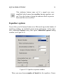
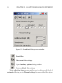
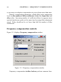
1
Sound Cleaner
Real-time noise cancellation and
speech enhancement software
User Manual
Operating Instructions
Speech Technology Center
St.Petersburg, Russia
Sound Cleaner
Real-time noise cancellation
and speech enhancement software
User Manual
Operating Instructions
Copyright
c 1999-2005 by Speech Technology Center Limited (STC
Copyright
Ltd.). All rights reserved.
Disclaimer
Speech Technology Center accepts no liability whatsoever for any loss
or injury incurred by the owner or by any third party while using this
product and its user manual and specifically disclaims any warranties,
merchantability or fitness for any particular purpose.
The contents of the User manual are subject to change without notice.
Dear Customer,
Thank you for purchasing this product! For optimum
performance and safety, please, read these instructions
carefully.
Contents
Necessary Information . . . . . . . . . . . . . . . . . . . . .
9
1
Overview
11
Delivery set . . . . . . . . . . . . . . . . . . . . . . . . . . . 12
Sound Cleaner capabilities . . . . . . . . . . . . . . . . . . . 12
Technical characteristics . . . . . . . . . . . . . . . . . . . . 13
2
Preparing Sound Cleaner for operation
System requirements . . . . . . . . . . .
Installing sound I/O hardware . . . . . . .
Installing the software . . . . . . . . . . .
Registration . . . . . . . . . . . . . . . .
3
.
.
.
.
.
.
.
.
.
.
.
.
.
.
.
.
.
.
.
.
.
.
.
.
.
.
.
.
15
15
16
17
17
Basic principles
General information . . . . . . . . . . . . . . . . .
Sound Cleaner main window and process windows
Menus . . . . . . . . . . . . . . . . . . . . . . . .
Sound . . . . . . . . . . . . . . . . . . . . .
Options . . . . . . . . . . . . . . . . . . . .
Typical schemes . . . . . . . . . . . . . . . .
Windows . . . . . . . . . . . . . . . . . . .
Project . . . . . . . . . . . . . . . . . . . . .
Text report . . . . . . . . . . . . . . . . . . .
.
.
.
.
.
.
.
.
.
.
.
.
.
.
.
.
.
.
.
.
.
.
.
.
.
.
.
.
.
.
.
.
.
.
.
.
.
.
.
.
.
.
.
.
.
.
.
.
.
.
.
.
.
.
19
19
20
22
22
23
23
24
26
26
5
.
.
.
.
.
.
.
.
.
.
.
.
.
.
.
.
6
CONTENTS
Register
Help . .
Toolbar . . .
Processes . .
.
.
.
.
.
.
.
.
.
.
.
.
.
.
.
.
.
.
.
.
.
.
.
.
.
.
.
.
.
.
.
.
.
.
.
.
.
.
.
.
.
.
.
.
.
.
.
.
.
.
.
.
.
.
.
.
.
.
.
.
.
.
.
.
.
.
.
.
.
.
.
.
.
.
.
.
.
.
.
.
.
.
.
.
.
.
.
.
.
.
.
.
.
.
.
.
.
.
.
.
.
.
.
.
26
27
27
28
4
Audio input
31
Input from a sound I/O device (ADC) . . . . . . . . . . . . . 31
Input from a file . . . . . . . . . . . . . . . . . . . . . . . . . 33
5
Audio output
Playback . . . . . . . . . . . . . . .
Pseudo stereo mode . . . . . .
Measure mode . . . . . . . . .
Saving signal to analog media
Save to file . . . . . . . . . . . . . .
.
.
.
.
.
.
.
.
.
.
.
.
.
.
.
.
.
.
.
.
.
.
.
.
.
.
.
.
.
.
.
.
.
.
.
.
.
.
.
.
.
.
.
.
.
.
.
.
.
.
.
.
.
.
.
.
.
.
.
.
.
.
.
.
.
.
.
.
.
.
37
37
38
39
39
40
6
Amplifier
43
7
Waveform
45
8
Equalizer
Equalizer controls . . . .
Equalizer toolbar . . . .
Equalizer options . . . .
Zooming and scrolling .
Adjusting filter FC . . .
“Elastic” mode . . . . .
Additional FC adjustment
9
.
.
.
.
.
.
.
.
.
.
.
.
.
.
.
.
.
.
.
.
.
.
.
.
.
.
.
.
.
.
.
.
.
.
.
.
.
.
.
.
.
.
.
.
.
.
.
.
.
.
.
.
.
.
.
.
.
.
.
.
.
.
.
.
.
.
.
.
.
.
.
.
.
.
.
.
.
.
.
.
.
.
.
.
.
.
.
.
.
.
.
.
.
.
.
.
.
.
.
.
.
.
.
.
.
.
.
.
.
.
.
.
.
.
.
.
.
.
.
.
.
.
.
.
.
.
.
.
.
.
.
.
.
.
.
.
.
.
.
.
47
48
49
51
53
53
53
54
Adaptive broadband filtering
55
Broadband filtering controls . . . . . . . . . . . . . . . . . . 55
Automatic mode . . . . . . . . . . . . . . . . . . . . . . 57
Manual mode . . . . . . . . . . . . . . . . . . . . . . . 57
7
CONTENTS
Model filtration . . . . . . . . . . . . . . . . . . . . . . . . . 60
10 Adaptive inverse filtration
61
Adaptive inverse filtering controls . . . . . . . . . . . . . . . 61
11 Frequency compensation
65
Adaptive compensation algorithm . . . . . . . . . . . . . . . 65
Frequency compensation controls . . . . . . . . . . . . . . . . 66
12 Slowing
69
13 Clipping
71
14 Mu-transformation
73
15 Impulse filtration
75
Impulse filtration algorithm . . . . . . . . . . . . . . . . . . . 75
Impulse filtration controls . . . . . . . . . . . . . . . . . . . . 76
16 Dynamic processing
79
Dynamic processing controls . . . . . . . . . . . . . . . . . . 79
17 Stereo processing
Independent two-channel processing . . .
StereoWave . . . . . . . . . . . . .
Adaptive stereo filtering . . . . . . . . . .
Stereo filtering in time domain . . .
Stereo filtering in frequency domain
Processing composite stereo signals . . .
.
.
.
.
.
.
81
81
82
82
83
85
87
18 Processing schemes
Scheme window . . . . . . . . . . . . . . . . . . . . . . . . .
Creating and adjusting the scheme . . . . . . . . . . . . . . .
Duplication . . . . . . . . . . . . . . . . . . . . . . . .
89
89
91
92
.
.
.
.
.
.
.
.
.
.
.
.
.
.
.
.
.
.
.
.
.
.
.
.
.
.
.
.
.
.
.
.
.
.
.
.
.
.
.
.
.
.
.
.
.
.
.
.
.
.
.
.
.
.
.
.
.
.
.
.
8
CONTENTS
Typical schemes . . . . . . . . . . . . . . . . . . . . . . . . . 92
Loading a typical scheme . . . . . . . . . . . . . . . . . 93
Saving current scheme as typical . . . . . . . . . . . . . 93
19 Sound Cleaner as Direct-X plug-in
95
20 Warranty
97
Tested and Approved . . . . . . . . . . . . . . . . . . . . . . 97
Support . . . . . . . . . . . . . . . . . . . . . . . . . . . . . 98
NECESSARY INFORMATION
9
Necessary Information
This manual describes Sound Cleaner ver. 5.x audio signal processing
software.
Listed below are the telephone numbers that you may need if any
questions or problems regarding the operation of Speech Technology
Center products arise:
Tel:
Fax:
Mail:
Office:
E-mail:
Web-site:
+7 (812) 331-0665
+7 (812) 327-9297
Russia, 196084, St.Petersburg, P.O. Box 515
4 Krasutskogo str., St.Petersburg
[email protected]
http://www.speechpro.com
When requesting assistance, you should have the following information readily available:
• name of the product and version number
• type of the computer and information about its configuration
• name of OS being used and its version number
• precise description of the problem.
Chapter 1
Overview
Sound Cleaner software is designed to process and play audio signals
in real-time mode. It may operate in any MS Windows environment1 .
Real-time audio processing makes Sound Cleaner a powerful tool useful for many different tasks, such as noise-cancellation during audiomonitoring and so on. It also drastically increases productivity and adjustment speed of processing tools.
The main tasks accomplished by Sound Cleaner are:
• Input of audio signals into PC memory and saving them on a hard
drive;
• Real-time noise-cancellation and improvement of the signal quality;
• Ascertainment of speech fragments in poor quality phonograms.
1
If common Windows multimedia sound I/O Card (Sound Blaster) is used. In other
cases see Installing sound I/O hardware in chapter 2 for more information about OS
supported.
11
12
CHAPTER 1. OVERVIEW
Delivery set
Sound Cleaner delivery set includes:
• Sound Cleaner software;
• Wave Assistant signal editor software;
• STC Sound I/O device (optional)1 .
Sound Cleaner capabilities
This manual describes Sound Cleaner software. For details on Wave
Assistant software and sound I/O devices see respective manuals and/or
technical descriptions.
Sound Cleaner software is capable to:
• Input and save audio signals from microphones and line inputs of
playback devices;
• Suppress different kinds of noises and compensate various interferences, including
I stationary and slowly varying additive complex narrowband (polyharmonic) and broadband noises;
I slowly varying amplitude-frequency interferences (record
or transmission channel AFC inconsistency);
I short pulse interferences;
I signal jumps;
I any kinds of additive noises, provided that audio signal is
received through two channels;
1
Instead of Sound Blaster card or other windows-compatible multimedia device the
software may be delivered with STC-H216 external USB-device. If Sound Cleaner is a
part of STC Ikar Lab complex, it will use STC-H189 sound I/O card.
TECHNICAL CHARACTERISTICS
13
• Process signals in real-time mode. Waveform and instant spectrum of a signal before and after the processing are continuously
displayed. You may always adjust any of the processing parameters, no matter which kind of filter is used, instantly monitoring
and listening to the effect of changes you have made;
• Adjust playback speed smoothly, without affecting sound pitch;
• Play selected phonogram fragment in loop mode;
• Play a phonogram in pseudo stereo mode with adjustable channel
delay;
• Optimize amplitude and frequency of a signal providing best possible audio perception;
• Operate as Direct-X plug-in for most common sound editors;
• Enter text using built-in text editor;
• Automatically create text report of signal processing;
• Save processing parameters for later usage.
Technical characteristics
Main technical parameters of Sound Cleaner are given in the table below.
Number of processed
channels
Processed signal format
Input signal format
Saved signal format
Sampling rate
1-2
8 or 16-bit PCM, µ-law, 24-bit float
16-bit PCM
16-bit PCM
8-48 kHz (chosen by user)
14
Audio file types
supported
Maximum phonogram
duration
Largest possible number of
adaptive filter coefficients
Gain adjustment range
Duration of fragment
played in loop mode
Playback speed coefficient
adjustment range
Channel delay value range
for pseudo stereo playback
CHAPTER 1. OVERVIEW
WAV, DAT, SDT
Limited only by free HD space,
depends on signal sampling rate
8192
From -60 to +60 dB
From 0.5 sec. up to whole phonogram
0.7 - 3
0-20 msec.
Chapter 2
Preparing Sound Cleaner for
operation
To prepare the software for operation you should:
1. Install sound I/O hardware and its drivers (if necessary).
2. Install Sound Cleaner and Wave Assistant.
System requirements
Sound Cleaner’s PC configuration demands are rather high due to realtime audio processing. For proper operation it requires:
• Pentium III/1000 MHz or better CPU;
• At least 25 Mb of free disk space;
• MS Windows 95/98/2000/XP OS (depending on sound I/O device
used - see Installing sound I/O hardware);
• At least 128 Mb or more RAM;
15
16
CHAPTER 2. PREPARING Sound Cleaner FOR OPERATION
• One free USB or PCI slot (depending on sound I/O device used);
• CD drive;
• Color monitor with 1024x768 dpi or better resolution;
• Keyboard, mouse.
During the operation, especially audio input and saving data in a
file Sound Cleaner software occupies nearly all the system resources
(CPU time, memory, local BUS flow and DMA channels). That’s why
we advise, that you close all other applications while running Sound
Cleaner in order to avoid possible loss of signal fragments.
Important!
Please, note, that Sound Cleaner has a high priority when addressing sound I/O device. This means, that if there is some
other application occupying the same device, it may lose access
to the I/O device after you shut down Sound Cleaner.
Installing sound I/O hardware
Sound Cleaner may receieve signals from one of three different sound
I/O devices: STC-H189, STC-H216 and Sound Blaster. Each of these
devices has certain OS limitations, namely, STC-H189 operates only
in MS Windows 98, while STC-H216 USB device is supported in MS
Windows 2000/XP. Sound Blaster card will work on PC with any MS
Windows OS installed.
If you use STC-H216 external USB-device or STC-H189 sound I/O
card, you will have to install it as well as necessary drivers according
to instructions provided in respective manual and/or device technical
description.
INSTALLING THE SOFTWARE
17
Installing the software
After you hardware is properly configured, you should install Sound
Cleaner software. To do it place the included CD in your CD-drive and
run setup.exe from Scleaner folder on this CD, then follow instructions
of the installation wizard. Sound Cleaner and Wave Assistant will be
installed on your computer.
Important!
If your PC operates under MS Windows 2000 or XP, make sure
you have access to the system register (i.e. you have administrator privileges) before you start the installation and registration.
You won’t need it after the registration is over.
Registration
After the installation the program will run in a demo mode corresponding to Premium version of the software (i.e. all the possible filters and
schemes included). You have to complete the registration procedure in
order to switch to work mode. To do it run Sound Cleaner from Programs/Speech Technology Center group. If you launch the software
for the first time, you will be offered to register immediately or do it
later, by choosing Register from the Register menu. In both cases just
follow the instructions of registration wizard. You will be asked to enter
your User name and Registration code; both of them are to be found
in register.inf file in Sclean folder on the CD. If there is no User name
specified, you may enter your own name in this field.
Chapter 3
Basic principles of Sound
Cleaner operation
General information
The program operates much like a mosaic - this means you may design
a scheme of signal processing, combining any of the provided modules (processes) in a desired sequence starting from sound Input. Each
process included in the scheme receives a signal form the previous one,
applies his own algorithm and then passes the processed signal to the
next module in the chain. Number of modules used consequently in a
single scheme is limited only by capabilities of your PC. Each module is
represented by an icon in the Scheme window located in the left part of
the Sound Cleaner main window (see Figure 3.1) and has its own dialog
window, where all the information and necessary controls are located.
Name of the process is indicated in the header of its dialog window.
The header also holds standard minimize and close (see Figure 3.1)
buttons as well as activate button. This button is used to apply the
module to a signal (activate it) or stop using it for signal processing
(deactivate).
19
20
CHAPTER 3. BASIC PRINCIPLES
Depending on signal format and type it may be processed along one
of the three processing scheme types:
Single-channel schemes are used for mono signals.
Two-channel schemes are designed to process signals in “left” and
“right” channel independently.
Stereo filtering scheme is very effective for stereo signals in most cases.
To help you master Sound Cleaner faster and easier we have included a set of standard noise-cancellation schemes in it. These schemes
provide good results for typical noises and interferences in most cases.
In case, if Sound Cleaner modules won’t suffice and you will need
additional tools, you may wish to employ Wave Assistant signal editor
supplied with Sound Cleaner. Currently processed signal will be automatically loaded in Wave Assistant if you launch it during processing.
The programs are linked so, that if you edit a fragment in Wave Assistant, the changes will be transferred to Sound Cleaner Input module,
and vice versa. To learn more about Wave Assistant signal editor refer
to its manual.
Sound Cleaner main window and process windows
Figure 3.1 displays main window of Sound Cleaner program.
As you see, it is a standard window; its header displays program
name and version number. There is a common menu string just below
the header and a toolbar, which contains shortcut buttons to most frequently used menu items. There is also the messages’ window at the
very bottom, while all the main part of the window is occupied with
process windows.
As Sound Cleaner loads, you will see all these windows unfold. You
may then arrange them as you wish, minimize or hide those, which you
Sound Cleaner MAIN WINDOW AND PROCESS WINDOWS
21
Figure 3.1: Sound Cleaner main window
don’t need. You may not, however, change size of these windows except
Equalizer.
Every window represents a single process (module) of the currently
loaded processing scheme (the only exception is Processing scheme
window described later in the separate chapter). Note, however, that if a
module is included in the scheme, this does not mean, that it is actually
used for signal processing, because it may be inactive. Each process
window header holds additional Activate button except common Minimize and Close:
. If this button is greyed, the module is inactive,
i.e. is not currently used for processing. To activate the process press
this button and see it turn red, which indicates, that the process is active.
Remember, that all the windows, no matter active or not, may be also
22
CHAPTER 3. BASIC PRINCIPLES
hidden (closed), minimized or displayed on the screen. For more details on managing process windows, see description of Windows menu
below.
Menus
Menu string is located just below the program header. Menu commands
control the program in general.
Sound
Sound menu contains commands, which manage input and output of
audio data:
Open file. Choosing this menu item will open standard “open file” dialog window. Specify the file you wish to open and process as a
signal source.
Save to file. You may choose or create a file to save the processed audio
signal into.
Start sound input. Choose this item to start input from sound I/O device.
Play file. This command starts sound input from a specified file.
Stop. Stops sound input.
Pause/Continue. Use this command to pause the playback and then
continue audio input.
Global reset. This command restores all the default filter (process) settings and removes all the information accumulated in buffers.
Cancel saving file. This item stops saving data in a file, but does not
affect other processes.
MENUS
23
Make composite stereo. Choose this command to create a composite
stereo - i.e. stereo signal combined from two independent mono
signals. See Processing composite stereo signals on page 87 for
more details.
Switch input channels. Swaps left and right channels of incoming stereo
signal.
Options
Commands in this menu set some additional parameters of saving and
loading files in Sound Cleaner.
Save. Use this command to specify a file, where current Sound Cleaner
configuration will be saved.
Load. There you may choose a file containing saved program configuration and load it.
Details submenu contains three items:
Save file input options when saving to cfg file. If you check this
option with the flag, the program will store name of currently loaded audio file and loop settings in configuration
file.
Ignore file input options when loading from cfg file. Check this
item to ignore audio file saved in configuration file.
Load sound file example together with typical scheme. If this
option is checked, Sound Cleaner will automatically load
a sound sample associated with particular scheme.
Typical schemes
This menu contains three submenus for managing typical schemes:
24
CHAPTER 3. BASIC PRINCIPLES
Load. . . You may choose a typical processing scheme from a list and
load it.
Save as. . . This item saves current scheme and configuration as a typical scheme. See Typical schemes section on page 92 for more
details on creating typical schemes.
Delete item. . . Choose this command to delete a typical scheme as well
as sound sample and configuration file associated with it.
Windows
Commands of this menu manage Sound Cleaner process windows.
Next. Activate next window.
Previous. Activate previous window.
Windows list. Opens Windows list dialog window (Figure 3.2).
Figure 3.2: Windows list dialog window
MENUS
25
In the left half of the window there is a list of processes currently
included in the scheme. Active modules are marked with an asterisk (*). Left-click on any module to select it. Process properties
field at the right side will display information about its current
status. You may place a flag there to minimize, hide or activate
the module.
There are also control buttons in the centre. They perform various operations on the selected process. Select button will unfold
the window of selected module and place it atop all others (you
may do the same if you double-click on any process in the list).
Delete button will remove the process from the scheme. Pressing
Replace or Insert will open a list of available modules. Doubleclick on any one of them to place it in the process list either instead of the selected one (Replace), or before it (Insert). Finally,
Place All button will return all the windows to default position
and status.
If you have used any of these commands, the dialog box will be
automatically closed. Otherwise press Cancel button to return to
Sound Cleaner main window.
Place All. Restores default position and status of the process windows.
Hide inactive. This command will hide windows of all currently inactive modules.
Minimize inactive. This item will minimize all windows of currently
inactive processes.
Hide minimized. Use this command to hide minimized windows.
Text edit. Opens a built-in text editor window.
View scheme. This item activates sound processing scheme window.
26
CHAPTER 3. BASIC PRINCIPLES
There is also Options submenu where you may set default operations with windows. Possible choices are Hide inactive, Minimize
inactive, Hide minimized and Windows standard.
Project
Commands of Project menu control and adjust signal processing schemes.
Load scheme. Choose and load existing processing scheme.
Save scheme. Save current scheme in a file specified by user.
View scheme. Activate Scheme window.
Load scheme + config, Save scheme + config. These commands load
and save processing scheme and configuration file associated with
this scheme.
Activate all. Activates all the modules in the currently loaded scheme.
Deactivate all. Makes all the modules in the current scheme inactive.
Text report
There is only one Create option in this menu. If you check it, the program will offer you to store processing parameters and current configuration in a text file each time you stop the playback. If you agree, current
scheme and configuration will also be saved in the same folder.
Register
There are two available items:
How to register? This command will display information explaining
how to register your copy of Sound Cleaner software.
TOOLBAR
27
Register. Launches registration wizard (see Registration in Chapter 2
for details).
Help
Help topics. This command will open Sound Cleaner help file.
About Sound Cleaner. Brings forth brief information about Sound Cleaner.
About STC. Displays brief information about Speech Technology Center.
Toolbar
Sound Cleaner toolbar buttons are shortcuts to most frequently used
menu commands.
Start audio input from I/O device (same as Sound/Start
sound input).
Start audio input from a file (Sound/Open file).
Open two mono files and combine them into a composite
stereo signal (Sound/Make composite stereo).
Save/Load program configuration (Options/Save; Options/Load).
Restore default parameters for all modules and clear all
buffers (Sound/Global reset).
Pause/continue signal processing
(Sound/Pause/Continue).
Start/stop direct listening to source audio signal (without
processing).
Open text editor window (Windows/Text edit).
28
CHAPTER 3. BASIC PRINCIPLES
Open Windows list window (Windows/Windows list).
Activate scheme window (Windows/View scheme;
Project/View scheme).
Load a saved scheme (Project/Load scheme).
Save current scheme (Project/Save scheme).
Switch to Direct-X plug-in mode.
Go to help contents (Help/Help topics).
Processes
Sound Cleaner provides consecutive signal processing, i.e. modules
are applied to a signal consecutively, one after one. This chain-like
sequence is called processing scheme and may be saved in .sch file.
Remember, that modules included in the scheme may be inactive. On
the other hand, windows of some processes, no matter active or not, may
be hidden or minimized. Table below displays names of processes, their
icons and short descriptions.
Name
Icon
Description
File input
Input signal from a file
Device input
Input signal from I/O device
Clipping
Clip the signal
Waveform
Signal waveform
Slowing
Changing signal playback speed
29
PROCESSES
Amplifying
Signal amplification
Save
Save signal to file
Equalizer
Parametric equalizer
Mu-transform
Signal transformation (µ-law)
Duplicate
Splitting a signal in two
Speaker
Signal playback
StereoWave
Stereo waveform of a signal
Freq. compensation
Frequency compensation
Impulse filter
Adaptive impulse filtration
Inverse filter
Adaptive inverse filtering
Broadband Filter
Broadband filtering of a signal
Dynamic processing
Signal dynamic processing
Frequency stereo
Frequency stereo filtration
Time stereo
Time stereo filtration
Chapter 4
Audio input
This chapter describes audio input process. There are two types of input
process depending on signal source: Input from sound I/O device and
Input from a file. Since Sound Cleaner may work only with one signal
source at a time, only one kind of audio input may be active and they
are united in the single Input module. Process window will change
according to type of signal source selected. Obviously, Input should
always be placed first in any processing scheme.
Input from a sound I/O device (ADC)
Main task of this module is to input audio signal from an external sound
source. To do it you should connect linear output of playback equipment to linear input of sound I/O device; or, if sound is received from a
microphone, connect it to the microphone input of the device.
During the input signal is converted into digital form and passed directly to Sound Cleaner. Processed signal is transferred to linear output
of the I/O device and may be at the same time saved via Save in a file
process. But much more effective way is to save the unprocessed signal
on a hard drive or any other media (to do it, activate only Input from
31
32
CHAPTER 4. AUDIO INPUT
sound I/O device and Save in a file), and then process it.
Figure 4.1 shows process window. Toolbar below the header contains standard input control buttons: Start input, Pause and Stop input. Read sound file button at the right side of the toolbar will switch
to Input from a file (see Input from a file).
Figure 4.1: Input from sound I/O device window
Use radio button to select Mono or Stereo input format. Remember,
that you have to create or load a scheme for two independent channels
to process stereo signal.
Frequency droplist contains possible values of sampling rate (for
STC-H189 you may enter any value within 8-48 kHz range). Default
value is 11025 Hz.
Important!
The higher you set input sampling rate, the larger your sound file
will be. At 11025 Hz one second of audio takes 22 Kbytes of
disk space, while at 22050 Hz – 44 Kbytes. In case of stereo
input necessary space is doubled.
INPUT FROM A FILE
33
Current time counter indicates duration of audio fragment currently
being inputted, while Lost counter below shows overall length of fragments omitted during current input and/or ADC. If you encounter audio
losses, please, consult Measure mode in chapter 5.
Input from a file
This process opens specified audio file, passes the information acquired
from it to the next active module and controls navigation within a phonogram. Sound Cleaner may input sound from DAT and WAV files. DAT
is an extension of audio files used by SIS software and Ikar Lab by STC.
WAV file formats supported are:
• 16-bit PCM;
• 8-bit PCM;
• µ- or A-law compression (8-bit);
• IEEE FLOAT - 24-bit.
Input from a file window is shown in Figure 4.2. Slider bar in the
center of the window displays current playback and input position. Just
below the header is the toolbar. Loop controls and indicators are at the
bottom of the window.
Some of the toolbar buttons are just common input and playback
controls: Open file, Start, Stop, Rewind, Fast Forward.
Other tools control specific input options. After pressing Go to file
time you may enter time (hh:mm:ss) from the beginning of a phonogram to start input and playback from. Current input position slider will
be placed accordingly. You may also drag the slider with your mouse
pointer or arrow keys.
You may select to play specific phonogram fragment in a cyclic loop
mode. To set beginning and end of the loop (ring), you may either place
34
CHAPTER 4. AUDIO INPUT
Figure 4.2: Input from sound file window
the slider in a desired location and press Mark start (end) of loop button, or simply click left or right mouse button (for left and right border,
respectively) over the indicator bar in the middle. Position of both ring
borders will be indicated by black markers under the bar, while whole
looped fragment will be highlighted with blue. At the same time Current loop borders digital indicators will display border positions from
the beginning of a phonogram (as hh:mm:ss). Press Loop mode on/off
button to turn this mode on and off. When it is active you should see
ON message appear at the bottom of the window, next to RING.
Start input from sound I/O device button will switch the window
to input from a device (see Input from a sound I/O device (ADC)).
View file button will launch Wave Assistant signal editor software
loading currently processed file and loop borders automatically. Import
borders button will do the opposite, namely, set currently selected in
Wave Assistant borders as loop borders in Sound Cleaner Input from a
file process window. See Wave Assistant manual for more information
on this software.
INPUT FROM A FILE
35
Sampling rate, mono/stereo input mode, total duration and current input position are indicated below the toolbar.
To the left of the input indicator bar you may see Move loop arrow
buttons. Press them to move both borders of the ring in any direction
with a Step specified in the field in the bottom-right corner of the window (in seconds).
Finally, STOP flag will, if it is set, enable Sound Cleaner to play the
“looped” fragment only once and then stop the input instead of doing it
over and over again (as loop-mode is supposed to work).
Chapter 5
Audio output
As with input there are actually two types of audio output available in
Sound Cleaner: playback (i.e. output to sound I/O device) and save
(output to file).
Playback
This process (also called Speaker) allows you to listen to either processed or source signal, as it is being inputted. So, if you wish to listen
to a signal while it is processed, ensure, that Speaker module is in the
scheme and active.
Playback window is shown in Figure 5.1.
You may choose to play the sound as mono, pseudo stereo or stereo.
In stereo mode you may also specify with a radio-button, which channel
you wish to listen to: L means only left channel, R – only right one, and
L,R – both. Do not forget to choose two-channel processing scheme
if you are going to play a signal as stereo (you may choose stereo.sch
standard scheme). For stereo and pseudo stereo you may also set the
inter-channel delay within 0-20 msec. range. To adjust delay value,
move the slider at the right side of the window.
37
38
CHAPTER 5. AUDIO OUTPUT
Figure 5.1: Playback process window
Playback Volume slider is located in the bottom part. It is linked to
MS Windows audio mixer. Try to avoid setting huge volume level, because this will usually lead to considerable signal distortions; it is much
more reasonable to adjust signal level with Amplifier (see chapter 6).
There is also MSR. button above the Delay slider. Use it to activate
Measure mode and calculate current PC load.
Pseudo stereo mode
In pseudo stereo mode a signal is played in one of two channels, and
then the same signal is played in the other one with a little delay. This
makes audio perception more comfortable and increases signal intelligibility; moreover, listeners tend to tire slower when pseudo stereo mode
is used. It is especially useful for determining text contents of very long
phonograms. In such case you should also try use different processing
types and change signal level from time to time.
If you wish to find more useful information about the properties of
PLAYBACK
39
human hearing important for perception of noisy speech phonograms, as
well as about main principles of determining contents of phonograms,
refer to STC Noise Cancellation and Text Decoding of Low Quality
Speech Recordings: Practical Approach1 .
Measure mode
As you turn on measure mode audio playback is paused and automatically calculated V value is displayed next to MSR. button. This value
represents time spent for signal processing compared to total phonogram
duration (in percents). V monitors PC load, if its value exceeds 100%,
it means, that your PC can not process the signal in real time, which, in
turn, may result in phonogram fragments being omitted. If you click on
the displayed value, calculation will be started over from this particular
instant.
To decrease PC load and minimize audio loss probability (if necessary) you should try to:
• Deactivate modules, which provide visual presentation of a signal
(Waveform, Equalizer);
• Decrease number of bands in Equalizer and frame size for adaptive filters;
• Decrease sampling rate;
• Use more fast and productive PC.
Saving signal to analog media
To save processed signal or its fragment on an audio tape or other analog medium, you should first connect record device (tape recorder) line
1
This brochure is delivered with STC Ikar Lab. It is also available for other Sound
Cleaner users – please, contact us for details.
40
CHAPTER 5. AUDIO OUTPUT
input to line output of your I/O device. Then adjust all the processing
parameters and signal level. Finally, you should simultaneously press
Start input button and record button of a tape recorder. Record will go
on until you stop or pause it.
Save to file
To record processed signal in a file you should use Save module. It
may be saved as WAV or SIS file in mono or stereo 16-bit PCM format,
with a sampling rate previously used for signal input. Stereo signals are
saved as WAV files only.
Toolbar of the Save process window (Figure 5.2) contains common
record control buttons.
Figure 5.2: Save process window
Save sound to file button opens a dialog window, where you choose
file and path to save a phonogram into. It will be displayed just below
SAVE TO FILE
41
the toolbar. After you have specified target file, start the input and the
signal will be saved. To temporarily stop saving signal, press Pause
button. Close file button will close the file, so you won’t be able to
continue recording into it. Finally, you may view and edit this file with
Wave Assistant by pressing Export file to Wave Assistant.
Chapter 6
Amplifier
Amplifier enables you to increase or decrease signal level up to 60 dB.
Its window is shown in Figure 6.1.
Figure 6.1: Amplifier process window
Gain coefficient is adjusted by the slider with 1 dB step; current
value is displayed at the right side of the bar. 0 dB value means, that
signal is not amplified.
During signal processing its level may go down due to corrections
of frequency characteristic and noise reduction. It weakens some components of a signal which may be then lost during further processing.
That’s why it is reasonable to amplify a signal during audio processing.
For most effective amplifying Waveform module is very useful. We
advise that you place it in your scheme right after the Amplifier to con43
44
CHAPTER 6. AMPLIFIER
trol the gain. If waveform of your signal nearly fills the waveform window in Y-direction, the gain is set correctly. Too low gain may lead
to gaps in useful signal; while over-amplified signal will be distorted
during playback.
If the gain value you set is too high, overflow indicator ( ) will
appear to the left of the slider bar. Click left mouse button over this
indicator to remove it.
Note, that over-amplifying will result in discomfort during playback
and in some cases may even cause ear injury, especially if a listener
uses headphones for signal playback. So you should avoid making significant gain adjustments instantly. Also remember, that deactivation
of processing modules may sometimes greatly increase signal level. For
such cases there is Dependent option in Amplifier’s system menu1 . Dependent amplifier will become active only if the process, which stays in
the scheme directly before the amplifier, is active. Otherwise amplifier
will be automatically rendered inactive.
1
You may open it by clicking on Microsoft icon in the window’s header.
Chapter 7
Waveform
This process is designed to view signals in waveform and monitor their
level. It is usually employed in a scheme at least twice: first time to
view just inputted signal, and then after all the processing to control it
before playback.
Figure 7.1: Waveform process window
45
46
CHAPTER 7. WAVEFORM
On Figure 7.1 you may see a waveform of a signal displayed in the
process window. Current time from phonogram start is displayed along
the X-axis, while Y represents signal amplitude in samples (within 2033000 range). To zoom Y-axis in and out there is a scalebar to the right
and + and - buttons. Blue area of the scale represents currently displayed
amplitude range. You may set new upper and lower border by clicking
on the bar with left or right mouse button respectively. Current borders
are indicated with black triangle markers at the right side of the bar and
their numerical expressions.
X-axis is not scalable, i.e. this process always displays instant
waveform of a signal. Note, that there is also Stereo waveform module
similar to Waveform, the only exception being that the former displays
waveforms of signals in both channels.
Chapter 8
Equalizer
This process displays signal spectrum and enables user to correct it via
inverse filtering and filter contrasting. Equalizer may work in automatic
or semi-automatic mode, it is also possible to tune the filter manually to
make fine spectrum adjustments. This module may suppress any stationary components of a signal regardless of their frequency and location;
it also may be used to raise the amplitude in a chosen spectral band.
This filter works well for phonograms containing considerable stationary noises such as power-line noise, mechanical and engine noises and
so on.
Number displayed in the window header is current FFT window
size. The larger it is, the larger is number of equalizer bands and more
fine and precise adjustments may be made. To select number of bands
you should open Options dialog box (described further). Try to set
largest possible number of bands to achieve best filtering quality and
precision, but remember, that it increases system load as well. FFT
window size is strictly determined by number of bands (in fact it is equal
to number of bands multiplied by four).
47
48
CHAPTER 8. EQUALIZER
Equalizer controls
Equalizer window may be displayed as standard (default) and large,
the only difference being its size and number of filter adjustment sliders.
Figure 8.1 shows standard equalizer window.
Figure 8.1: Equalizer process window
You can see toolbar below the window header and a black window,
where current signal (yellow) and filter (green) spectra are displayed.
EQUALIZER TOOLBAR
49
X-axis zoom bar is just under this window; currently visible area is
marked with blue. Two red markers at the upper edge of the spectrum
window indicate bandpass borders (you may drag them to change the
borders). Lower half of the window is occupied with filter band adjustment sliders; ”Elastic” mode and Additional FC controls.
Equalizer toolbar
Equalizer toolbar contains most important and frequently used process
controls:
Set maximum horizontal zoom, i.e. each adjustment
slider corresponds to a single filter band.
Zoom in, increasing X-axis scale two times.
Zoom out, decreasing X-axis scale two times.
Zoom out, showing all the spectrum from 0 Hz up to half
of the sampling rate.
Reset filter, placing all the adjustment sliders to zero.
Autoscale Y-axis according to maximum and minimum
spectrum values.
Select a rectangular area to be displayed in the spectrum
window. Select it and press left button and see a dashed
rectangle appear, then drag it to specify the area you wish
to view, and release the mouse button. Selected area will
be enlarged to fit the spectrum window.
50
CHAPTER 8. EQUALIZER
Switch Y-axis from linear to logarithmic (dB) scale.
When this button is pressed, equalizer displays signal in
logarithmic scale, otherwise the scale is linear.
Turn spectrum accumulation on and off. While this button is pressed, the program accumulates signal calculating
and displaying average spectrum. Depress it to switch
back to instant spectrum.
Build inverse or harmonic filter (selected by user) basing
on current spectrum (either instant or average, if spectrum
accumulation is on). Pressing this button
automatically stops spectrum accumulation. Note, that either filter is calculated within bandpass borders only.
Contrast the filter. See Equalizer options section for more
information about filter contrasting.
Important!
If you have turned on filter contrasting in Options menu, it will
be automatically done during inverse filter calculation and/or automatic filtration. In this case pressing this button will make
Sound Cleaner to contrast the filter once more.
Automatic filtration button turns off spectrum accumulation and then inverse or harmonic filter calculation (filter
type is selected by user). You may set time of automatic
spectrum accumulation in Options menu.
Switch between standard and large equalizer window.
EQUALIZER OPTIONS
51
This indicator button turns red if a signal was overamplified which caused an overflow during equalizer output. Press the button to bring the indicator back to passive
state until the next overflow.
Equalizer options
If you click your left mouse button over Microsoft sign in the header of
equalizer window, its standard system menu will appear. It has, however, additional Options entry, that opens Additional options dialog
window (see Figure 8.2).
Figure 8.2: Equalizer options window
There you may choose number of bands for the equalizer. Gener-
52
CHAPTER 8. EQUALIZER
ally speaking, setting greater number of bands will increase filter performance as well as your PC load.
Filter contrasting options field occupies the center of the window.
Contrasting means that Sound Cleaner will automatically detect narrow
gaps in the filter FC and then broaden and deepen them. This operation
may considerably improve filtering quality, especially if there are clear
local noise peaks in the spectrum of a signal. To enable filter contrasting check the respective flag in the bottom part of the window. Then
adjust contrasting options:
• Discrimination level parameter represents relation between filter
value in the gap and on its edge. The program uses it to determine
which filter gaps are to be contrasted. 1 value means, that it will
contrast all the local minimums; 0 – filter won’t change. Values
around 0,5 will make the program to skip small (usually, natural)
minimums at the same time contrasting large and distinct gaps.
• Analysis window width value determines maximum width of a
gap (in Hz), which will be considered ”narrow” and, therefore,
will be subject to contrasting. Default value is 70 Hz.
• High intensity flag, when checked, will slightly broaden the gaps
in addition to common contrasting effect.
At the lower part of the screen you may see a group of additional
controls. Accumulation time value is a duration of spectrum accumulation for automatic filter calculation. Filter contrasting flag turns on
respective operation, as was mentioned earlier; Graphics drawing may
be turned off to disable drawing of signal spectrum, enhancing performance of weak PCs.
OK button will close the window saving all the changes, Cancel
will discard them.
ZOOMING AND SCROLLING
53
Zooming and scrolling
To zoom signal spectrum window in and out, you may use appropriate
toolbar buttons (see Equalizer toolbar), “<>” buttons and horizontal
zoom bar located below the spectrum area. Blue-marked fragment of
this bar indicates, which part of the whole spectrum is currently displayed. If the whole bar is blue, then all the spectrum is displayed (if,
for example,
button was pressed).
Click left or right mouse button over the bar to set respective borders
of displayed spectrum. You may also scroll it with arrow buttons to the
left of the bar or with arrow keys. In the latter case you have to set the
focus on the bar. Pressing the button or key moves the displayed area
1/16 (1/32 for large window) part of the whole signal area to the right or
left.
Adjusting filter FC
There are 16 spectrum adjustment sliders in standard window and 32 in
the large. Current signal level adjustment value in controlled band is
indicated above each slider (in dB). Highest and lowest possible values
(+20/-72 dB), which correspond to extreme slider positions, are given
near the left edge of the window. There you may also see a number
of spectral bands, which are currently controlled by a single slider. If
you zoom in and out, this number will change, reaching 1 at maximum
X-axis zoom level.
“Elastic” mode
“Elastic” mode enables you to simultaneously adjust several sliders as
if they were bound together with an elastic thread. In this mode it is
much easier to change filter FC smoothly.
54
CHAPTER 8. EQUALIZER
To include sliders in an “elastic” group, you should click left and
right mouse button on the bar below the sliders, thus setting left and
right border of the group. Selected group will be marked with blue
indicator in the bar.
Note, that only sliders (not signal bands!) may be grouped and
bound together. This means, that if you zoom in or out, those sliders,
which you have previously included in a group will control other signal
bands.
x button to the left of the “elastic” mode bar turns linearization
(smoothing) on and off. Outlines of a filter built in “elastic” mode will
be smooth (not jagged) if this mode is on.
Additional FC adjustment
Sliders Q1 and Q2 located at the very bottom of the screen provide
additional filter FC adjustment, which are added to values set by FC
adjustment sliders. This extra adjustment makes speech sound more
natural and be more comfortable for the listener’s perception.
Q1 adjusts FC convexity within 100-800 Hz frequency band. Q2
changes FC increase/decrease for every 1000 Hz starting from 1000 Hz.
Both sliders work within -18/+18 dB range with current value indicated
to the left of it.
Chapter 9
Adaptive broadband filtering
Adaptive broadband filter is based upon adaptive frequency algorithm. This algorithm is designed to suppress broadband and periodic
noises due to electric pick-ups or mechanic vibrations, room and street
noise, communication channel or record equipment interferences. You
may hear these noises as hum, rumbling, hisses or roars. Note, that this
algorithm performs at SNR not worse than -5 Hz. It is nearly impossible
to remove such noises with other methods, such as one-channel adaptive filtration, spectrum smoothing or equalizer, because they are spread
across the whole spectrum and intersect with speech signal.
Broadband filtering controls
Broadband filter window is shown in Figure 9.1.
There are four process control buttons located on the toolbar:
55
56
CHAPTER 9. ADAPTIVE BROADBAND FILTERING
Figure 9.1: Broadband filter process window
Reset filter
Fix current filter settings
Open Auxiliary options dialog window
Restore default filter settings
Noise reduction degree group enables you to either specify level of
automatic filtering, or use Manual settings for more subtle filter adjust-
BROADBAND FILTERING CONTROLS
57
ment. Additional depth (available only in automatic mode), Smoothness and Frame size auto-tuning fields will be described later.
Automatic mode
Automatic noise filtering works best if you have to get reliable results
very fast. It also does not demand from the user any special noisefiltering skills and experience.
All you have to do in this mode is specify desired noise-reduction
level (soft, standard or hard). Each level has also its own inner scale,
so in total you have 10 grades of noise-cancellation. Just choose appropriate radio-button and the program will automatically select optimum
values of noise suppression Intensity and Depth. Note, that filter needs
some time to tune itself to a specific noise, so you should try to avoid
making considerable instant changes of noise-reduction level.
You may also choose Additional depth of noise-reduction within
-15/+15 dB range and enable Frame size auto-tuning. These settings
will be described later in this chapter.
Manual mode
For experienced users, who are not completely satisfied with results of
automatic processing, there is a possibility to tune all the necessary
parameters manually. To do it just select Manual settings in Noisereduction degree group. This will automatically open Auxiliary options window (Figure 9.2).
Main and most important parameters of broadband filtering are suppression Intensity and Depth located in Manual settings group.
Suppression intensity adjusts inflection point of SNR/suppression
curve (1-40). Suppression depth may be set within 1-80 range; it determines largest possible suppression of spectral components of a signal.
Generally speaking, increasing both these values will lead to better
noise-reduction, but useful signal may also be suppressed and speech
58
CHAPTER 9. ADAPTIVE BROADBAND FILTERING
Figure 9.2: BB filter auxiliary options window
quality and intelligibility reduced. We advise, that you adjust these parameters very carefully and always control achieved effects.
Time constant field sets the time of filter adjustment to signal spectrum variations. In most common cases 3-4 sec. is recommended, for
non stationary noises the value should be slightly decreased (to 1-2 seconds). Setting less than 1 second time constant will, in most cases,
greatly decrease speech quality.
T-smoothing parameter controls time smoothing of filter coefficients.
It usually helps to remove musical noises which sometimes appear after broadband processing. For large SNR values and signal sampling
rate less, than 11025 0-1 values should suffice, while bad SNR and huge
sampling rates may demand T-smoothing of approximately 5. Default
BROADBAND FILTERING CONTROLS
59
value is 1.
In the Frame size list you may choose spectral resolution, i.e. number of spectral bands and size of a signal processed audio block. As
this value is increased, more different sounds are mixed together in a
single block, so there are fewer spectral bands, containing no speech
signal. Larger frame size tends to produce considerable echo effect.
On the other side, smaller values lead to weaker and less precise noisereduction. Available Frame size range is 128-4096 with 512 being the
default value. In fact, it depends on sampling rate of a signal, but you
may check Frame size auto-tuning in the filter main window to make
Sound Cleaner to choose frame size automatically.
Harmonic suppression flag turns on additional suppression of harmonic noises.
Timbre correction is necessary to remove unnecessary low- and
high-frequency components of a signal, i.e. configure the bandpass so,
that it would suit human speech frequency range. In this case speech
becomes more intelligible and comfortable to listen to. You may turn
timbre correction on and off with ON/OFF flag and adjust its parameters.
Speech . . . from sets bandpass lower border and Speech . . . to – the
upper border. For 10-11 kHz sampling rate 200 Hz lower and 3600 Hz
upper borders are recommended. In fact, these values depend on signal
quality and sampling rate. As a rule you should somewhat lift the upper
border value. If you encounter strong broadband noise (hisses, rumbles),
it is reasonable to decrease this value to 2900-3200 Hz.
HF and LF amplify parameters adjust sound level in high- or lowfrequency area. They work exactly the same as Q1 and Q2 sliders of the
equalizer (see Additional FC adjustment of the previous chapter). For
common cases it may be useful to reduce high frequencies, setting HF
amplify value to approximately -3/-6 dB. This is not a rule, however, in
fact, you may have to leave it unchanged or even raise this value.
There are also two parameters of the main window, which are not
60
CHAPTER 9. ADAPTIVE BROADBAND FILTERING
yet described. Smoothness defines frequency smoothing of filter coefficients which (like T-smoothing) is useful for suppressing musical tones,
which sometimes appear after processing.
Frame size auto-tuning makes Sound Cleaner automatically choose
the frame size according to sampling rate of the signal. If you try to do
it manually, this flag will be automatically removed.
Model filtration
If a noise you are going to remove with the broadband filter is stationary or close to it (i.e. spectral envelope does not change in time), and
a phonogram contains a fragment of this noise without useful signal
(this fragment should be long enough for the filter to adjust itself), then
you may use this fragment as a model for filtration. To do it find such
fragment (Wave assistant may be very helpful) and run it in the loop
mode. Adjust the broadband filter so, that it would completely suppress
the signal (noise in this case), then press “Fix” button on the toolbar.
Filter coefficients will be set and used for filtering the entire phonogram
without any adjustment.
Chapter 10
Adaptive inverse filtration
Adaptive inverse filtration process is based upon Adaptive Spectral
Correction algorithm, sometimes called also Adaptive Spectral Smoothing.
Adaptive inverse filtration effectively suppresses strong periodic
noises from electrical pick-ups or mechanical vibrations thus recovering speech signal and equalizing signal AFC. It amplifies weaker signal
components and suppresses the stronger ones at the same time. The average spectrum therefore tends to approach the flat spectrum unmasking
the speech signal and improving its intelligibility. Broadband noises,
however, usually become stronger making signal perception less comfortable. It means that you should try to reach a compromise between
noise reduction and speech perception.
Adaptive inverse filtering controls
Inverse filtration window is shown in Figure 10.1. Its toolbar contains
four common filter control buttons:
61
62
CHAPTER 10. ADAPTIVE INVERSE FILTRATION
Reset filter
Fix current filter settings
Open Auxiliary options dialog window
Restore default filter settings
Figure 10.1: Adaptive inverse filter window
Time constant slider sets the time which the filter needs to adjust
to variations of the spectrum within 0,1–10 seconds range. In common
ADAPTIVE INVERSE FILTERING CONTROLS
63
cases 3-4 sec. values are recommended; for non stationary noises decreasing this value to 1-2 seconds may be useful.
Max. amplification limits weak spectrum components gain for any
given frequency. It is necessary to avoid raising the level of noise during
the pauses. 20-30 dB values are recommended.
Inversion threshold value marks certain level of the signal which
is considered the border between “weak” and “strong”, i.e. all the components below that level are amplified, while those, that exceed it are
weakened.
Ops. toolbar button opens Auxiliary options dialog window (Figure 10.2). You may choose frame size from the list box and configure Timbre correction parameters. Timbre correction settings are described in Manual mode section of Adaptive broadband filtering.
Figure 10.2: Adaptive inverse filter auxiliary options window
Chapter 11
Frequency compensation
Adaptive compensation process uses Widrow adaptive filtering algorithm for one-channel adaptive compensation. It is most effective for
narrow-band stationary and regular interferences. The filter adjusts itself smoothly maintaining good useful signal (speech) quality. Except
frequency compensation this process also provides adaptive compensation in time domain. It also suppresses harmonic interferences provided
their phase is more or less stable.
Adaptive compensation algorithm
Adaptive compensation enables user to remove both narrowband stationary interferences as well as regular ones (vibrations, power-line pickups, electrical device noises, steady music, room, car and water noises,
reverberation and so on). One-channel adaptive frequency compensation recovers the speech suppressing tonal interference by 20–40 dB.
Main advantage of this process is its capability to preserve the speech
signal much better than other filters usually do. It happens because the
interference is in this case subtracted from a signal and not multiplied by
0. In some cases only a part of periodic interference may be removed,
65
66
CHAPTER 11. FREQUENCY COMPENSATION
so you may use adaptive compensation in your scheme more than once.
Primary compensation parameters, which affect noise suppression
level, are the number of filter coefficients (defined by frame size) and
delay value. Increasing number of coefficient allows to suppress more
spectral interference peaks at the same time lowering filter adjustment
speed. Delay should not be set lower than half the number of filter
coefficients.
Frequency compensation controls
Figure 11.1 displays Frequency compensation window.
Figure 11.1: Frequency compensation window
Frequency compensation toolbar buttons perform common func-
FREQUENCY COMPENSATION CONTROLS
67
tions: Reset filter, Fix filter, Auxiliary options and Restore default
filter settings.
To choose compensation mode use radio-buttons at the right side of
the screen:
Harmonic suppression allows to remove harmonic interferences provided its phase is relatively stable.
Compensation is used to suppress interferences in frequency domain.
Time method activates compensation in time domain.
Frame size is the most important compensation parameter in any
mode. It defines number of spectral bands and processed data block
size. The larger it is, the more filter coefficients is used for compensation, and, therefore, more spectral peaks may be removed. In common
cases greater frame size will lead to better compensation, though it may
also cause echo effects. 512-2048 samples should be sufficient for most
phonograms.
Adaptation speed slider sets filter adjustment time, i.e. time the
filter needs to tune itself to the variations of interference spectrum. For
common cases values around 20-25 are recommended. If an interference
spectral parameters change quickly you should try to increase adaptation speed and vice versa. Remember, that large filter adjustment speed
tends to impair speech signal quality.
Delay may be set for time (0–1000 msec.) and frequency (from
0 to frame size) compensation. This slider sets an interval between
the fragment, where the interference is calculated and the beginning of
compensation. For frequency compensation delay should not be less
than one half of the chosen frame size; for time compensation – 25
msec. or more is recommended. Otherwise speech signal may be greatly
distorted.
Frequency compensation Auxiliary options window (Figure 11.2)
is opened with Ops. toolbar button. It contains Timbre correction settings (see chapter 9, Manual mode) and Adaptation threshold slider.
68
CHAPTER 11. FREQUENCY COMPENSATION
Figure 11.2: Frequency compensation auxiliary options window
Adaptation threshold may vary within 1-32000 dB. If signal amplitude exceeds this value, necessary filter adjustments are made. Thus,
you may set the threshold to keep filter unchanged during low signal
level phonogram fragments, for example, when there is no interference.
Chapter 12
Slowing
This process is used to increase or decrease signal playback speed
without changing the voice pitch. The window (Figure 12.1) contains
only playback speed adjustment slider. Current speed coefficient (in %)
is displayed at the right side.
Figure 12.1: Slowing process window
Speed adjustment is usually employed in the very end of the scheme,
just before the playback of processed sound.
69
Chapter 13
Clipping
This process is necessary to limit amplitude of a signal, thus removing
strong bursts and smoothing the signal’s level. On the other hand it
does not significantly affect speech intelligibility. Clipping is also very
useful for rough clearing of harmonic interferences, provided there are
rather long fragments of interference, and its level exceeds the level of
useful signal.
Figure 13.1: Clipping process window
71
72
CHAPTER 13. CLIPPING
To clip the signal you just have to point minimum and maximum
signal level values using MIN and MAX sliders in the process window
(Figure 13.1). Current value is shown in a field above the slider.
Then all the values of signal level, which are higher than maximum
and lower than minimum value are discarded and made equal to respective value.
Chapter 14
Mu-transformation
Mu-transformation is recommended if signal fragments greatly differ
in level. It happens, for example, if one of the speakers is located near
the microphone and the other one - quite far from it. During the transformation weak fragments are greatly amplified, while strong ones are
amplified insignificantly or not amplified at all. This process is in fact
similar to dynamic processing described later in chapter 16 but works
faster.
Figure 14.1: Mu-transformation process window
73
74
CHAPTER 14. MU-TRANSFORMATION
There are two parameters of mu-transformation (see Figure 14.1).
Mu MAX defines highest possible level of signal after the transformation (1-32000).
Contrast value sets the number of mu-transformation coefficients
and defines signal level range to be transformed with maximum amplification. 1 value means that all the input signal will be evenly amplified
and brought to maximum during transformation. 1000 value will, on the
contrary, greatly amplify the weak signals, reducing at the same time the
level of strong ones.
Chapter 15
Impulse filtration
Adaptive impulse filtering automatically restores speech or musical
fragments distorted and masked by various pulse interferences such
as clicks, radio noises, knocks and so on. Adaptive impulse filtering
algorithms improve quality of the signal suppressing powerful signal
impulses and thus unmasking useful audio signal and increasing its intelligibility.
Impulse filtration algorithm
During impulse filtration Sound Cleaner substitutes impulses with smoothened
and weakened interpolated signals. If the program does not detect an impulse, it leaves the fragment unchanged. It also does not suppress tonal
interferences and broadband noises. Impulse detection is based upon the
information, which the program has about differences between useful
signal and an interference. Thus, setting filtration parameters correctly
is critical for effective processing.
75
76
CHAPTER 15. IMPULSE FILTRATION
Impulse filtration controls
Impulse filter window is shown in Figure 15.1.
Figure 15.1: Impulse filtration process window
The process may work in two modes, switched by the radio-button
at the bottom edge of the window:
Impulse hindrances – in this mode short (up to 100 samples) impulses will be smoothened and removed, being substituted with values
interpolated from the useful signal.
Amplitude distortions works for the the same short impulses as
well as for distortions due to overload (if, for example, ADC limitations were violated during audio input). In this mode the distortions are
smoothened, so you will not have to adjust any processing parameters.
Impulse filtration is configured with three sliders:
Threshold is necessary to detect and locate the impulses basing
upon their energy. Default value is 6. Decreasing detection threshold
will make the program locate weaker impulses. Setting higher threshold
values will leave the weak impulses intact; if the value you have set is
too small, then sudden changes of useful signal level will be considered
impulse interferences and removed.
Smoothing slider controls detection and localization of impulses
IMPULSE FILTRATION CONTROLS
77
with respect to their duration. Decreasing this coefficient will enable
the program to detect short and weak impulses, impairing, however, localization of longer impulses.
Contrast works approximately the same as threshold, but performs
more subtle filter tuning. Generally, increasing the contrast will enable
Sound Cleaner to detect more impulses. It is usually adjusted in the end,
after appropriate threshold and smoothing values are selected.
Except these settings impulse filter is also supplied with common
Reset filter and Restore default filter settings buttons located on the
toolbar.
Chapter 16
Dynamic processing
Dynamic signal processing improves its intelligibility if the signal fragments greatly differ in level, in case of resonant knocks (i.e. long impulses) and room noises. Dynamic processing algorithms improve and
unmask the signal suppressing powerful impulses and clicks and reduce
the listener’s fatigue for long phonograms. It is in some way similar to
mu-transformation (see chapter 14. Mu-transformation), but works
a little slower. On the other hand dynamic processing has a major advantage over mu-transformation: it brings no distortions into the signal.
Dynamic processing controls
Figure 16.1 displays dynamic processing window.
Toolbar contains common Reset filter and Restore default filter
settings buttons. Threshold set by the slider in the bottom of the window is very important. It is used to distinguish strong and weak signals.
If you choose to weaken the strong signals, they will be also brought
down exactly to the threshold value; while weak signals will be amplified to one tenth of this threshold.
Radio-buttons in the middle set separate dynamic processing modes
79
80
CHAPTER 16. DYNAMIC PROCESSING
Figure 16.1: Dynamic processing window
for strong and weak signals. Strong signals may remain at their initial level or be weakened, which is usually done to bring loud speech
down to threshold value or eliminate strong and long (more than 20 sec.)
impulses (knocks).
You may also amplify weak signals to balance the level of speech
for two speakers; leave them unchanged (remain); or weaken them,
which may be useful for suppressing the noise in pauses between loud
speech fragments.
Chapter 17
Stereo processing
There are two different kinds of stereo processing available in Sound
Cleaner: two-channel signal processing and adaptive stereo filtering.
In the first case the sound in each channel is processed independently,
while in the second case data acquired from one channel (called referent) are used for filtering the signal in the second one (primary channel).
Independent two-channel processing
Before you start stereo processing you should load appropriate processing scheme (Typical schemes/Load. . . /Standard scheme of 2-channel
signal processing) or create a two-channel scheme yourself. Then you
may use any of the described processes for each channel independently.
If you have used different filters or different parameters for these
two channels, you will have to include the Stereo Wave process into
your scheme.
81
82
CHAPTER 17. STEREO PROCESSING
StereoWave
This process is used to display audio data from both processed channels
in a single window. It is absolutely similar to Waveform (see chapter 7). The only exception are the Hide left/Hide right checkboxes
above the waveform, which allows to hide a waveform of a signal acquired through particular channel.
Adaptive stereo filtering
As in the previous case, you will have to create or load a scheme, where
one of the adaptive stereo filtration modules is present. There are two
appropriate typical schemes (Typical schemes/Load. . . /Stereo filtration): for filtration in time and frequency domain. The only difference
between these two schemes is the type of active stereo filter (using them
together for the same signal makes no sense anyway).
Two-channel adaptive filtration algorithms are designed to suppress
both unstationary broadband (background speech, radio, room noise)
and periodical (vibrations, power-line pick-ups) noises. The backbone
of these methods is acquiring the information about the interference
from the reference channel and the using it to remove this interference
from the primary channel.
Stereo filtering has, however, a serious limitation: it may be effectively applied only if following conditions were met during the audio
record:
• Stereoscopic base (i.e. distance between the microphones) should
not be less, than 10 cm;
• Primary and reference channel microphones should be located at
different distance from the signal source. The same is true for the
source of interference;
ADAPTIVE STEREO FILTERING
83
• Both useful and interfering signal received by microphones should
come directly from the source (not be reflected).
Stereo filtering in time domain
Time filtration allows to suppress unstationary broadband noise (speech,
music) and periodical interferences (vibrations, power-line pick-ups)
from some point-like source (e.g. radio set). Its process window is
shown in Figure 17.1.
Figure 17.1: Time filtration process window
Toolbar contains common Reset filter, Fix filter and Set default
filter values buttons. There are also two additional L and R buttons
necessary to specify, which channel should be considered primary (L
stays for left channel and R - for right).
Frame size should be selected from the list and may vary between
50 and 2000 counts. We recommend you to listen to results after ev-
84
CHAPTER 17. STEREO PROCESSING
ery frame size change and then make further adjustments, if necessary.
Frame size defines number of filter coefficients; large values usually
slow down filter adjustment but provide better filter performance, especially when removing reverberation noises.
Background output is used to monitor and control filter performance. If you place this flag, the program will play back the signal
which, with current filter settings, is considered noise and removed. If
all the settings are correct, background output should contain only interference signal. Nevertheless, if you hear useful signal in the background, there may be two reasons for it:
1. You may have swapped primary and reference channel. In this
case all you have to do is just choose the other channel as primary
with L/R toolbar buttons.
2. Useful signal is partially removed. It means, that reference channel microphone receives not only interference, but also useful signal. To solve this problem try moving reference channel microphone, if possible, to minimize useful signal received by it.
Adaptation speed slider defines filter auto-adjustment speed. For
unstationary noises 26-29 values are recommended, while for slow varying ones 22-25 should suffice.
Reference channel delay is a parameter critical for effective stereo
processing. It is set in counts and lies within -30 – 1000 borders. Delay
should be chosen with respect to one important rule: primary channel
interference should never anticipate the reference channel. For example, if primary and reference signal are simultaneous, setting positive
delay will make correct filtering impossible. Introducing, on the contrary, small negative delay will lead to reference signal anticipating the
primary, which is necessary for correct filter adjustment and effective
processing.
In most cases delay should be close to 0 or a little bit less. But if the
reference signal is recorded from an interfering device output, setting
ADAPTIVE STEREO FILTERING
85
huge positive delay may be necessary.
Note, that 1 count delay at 8000 Hz sampling rate is equal to 2,3 cm
propagation difference (i.e. difference between distances the signal has
to cover in order to reach primary and reference microphone). Thus, 1
m propagation difference will demand about 40 counts delay for good
processing results.
Stereo filtering in frequency domain
Frequency (spectral) filtration differs from filtration in time domain
only in processing methods and conditions. Delay for the frequency
filtration is set in centimeters, not in counts. It represents the difference
of distances between microphones and interference source. In all other
aspects delay has the same meaning and is set the same way as for time
filtering. Frame size, background output and adaptation speed also
work exactly as described in previous section.
Frequency stereo filtration window is shown in Figure 17.2.
Process toolbar is similar to time filtration window, the only difference is Options button, which opens frequency filtering auxiliary options dialog window. In this window you may configure standard timbre correction settings and set maximum suppression depth.
There are three available modes of Frequency filtration. They are
selected with the radio-buttons.
Point source noise mode works approximately the same as time
filtration, but with better speed because of larger frame size values. On
the other hand the filter adjusts itself to an interference a little slower.
It is very effective when the reference signal is recorded from a line
output of interfering device (e.g. radio set). In this case you should set
appropriate positive delay because the source is actually located in some
distance.
Reference channel noise mode removes noise of some distance
source (working engine, background speech) from the primary chan-
86
CHAPTER 17. STEREO PROCESSING
Figure 17.2: Frequency filtration process window
nel provided the reference microphone is set next to this source. You
will also have to set an appropriate positive delay.
Ambient noise mode allows to clear useful signal if it is received by
two closely (30-70 cm) located microphones from a nearby (less than
1,5 m) source, removing reflected noise of a distant source (air conditioner, orchestra and so on). It works best if the interference source is
located symmetrically relative to the pair of microphones. If not, you
may correct the symmetry with appropriate delay setting.
PROCESSING COMPOSITE STEREO SIGNALS
87
Processing composite stereo signals
In Sound Cleaner there is a possibility to create a composite stereo
signal by combining two different mono signals into one. It may help
you to apply adaptive stereo processing to signals recorded by two
different microphones.
To be merged in a composite stereo mono signals must be of the
same type (wav, dat) and recorded with the same sampling rate. If these
signals have different length, then duration of resulting composite stereo
will be equal to the length of the shorter signal.
on the toolbar of the main
To create a composite stereo press
Sound Cleaner window. The program will display a dialog window
(Figure 17.3).
Figure 17.3: Composite stereo creation window
You will have to select files to be included in a composite stereo.
If they meet all the necessary conditions, you may load the signal and
process it as a common stereo file with all the available filters.
Chapter 18
Creating and editing
processing schemes
During noise-cancellation you will once surely face tasks, unaccomplishable by standard means and typical schemes. That’s why Sound
Cleaner includes lots of possibilities for flexible tuning of processing
procedure. One of these is creating you own unique processing scheme
or editing an existing one.
Scheme window
Scheme window (Figure 18.1) displays and manages signal processing
sequence. This window is usually located at the left edge of the main
Sound Cleaner window. You may open it with Project/View scheme if
the window is not displayed by default.
The scheme is displayed in the window as a sequence of icons. Each
one represents a process included in the current scheme. Icons are connected with black lines, which show the way of a processed signal passing through the scheme. Icon’s background color indicates status of the
process: orange background marks active processes and gray – passive
89
90
CHAPTER 18. PROCESSING SCHEMES
Figure 18.1: Scheme window
ones. Double-clicking on an icon places its window on top in the Sound
Cleaner window.
Icons of all the available processes are displayed in a column to the
right of the scheme. There are also up and down arrows for scrolling the
window. Note, that left-clicking on these arrows will scroll the scheme
and right-clicking – available icons.
At the right edge of the window there is a column of scheme control
CREATING AND ADJUSTING THE SCHEME
91
buttons. They correspond to commands of the system menu (you may
open it by clicking over the icon in the window header):
Load scheme. Choose an existing scheme and load it.
Save scheme. Save current scheme.
Change scale. View the scheme in smaller scale. It is
useful for large and complicated schemes, which do not fit
the regular window.
Redraw scheme. Automatically redraw the scheme optimizing its structure. Before you redraw the scheme,
ensure, that there are incoming connections for all the processes
(except sound input).
Erase scheme. Clears currently loaded scheme.
Change style. This button minimizes scheme window hiding all the icons and control buttons. To return to default
window style activate system menu command.
Swap input channels.
stereo signals.
Swaps incoming channels for
Creating and adjusting the scheme
Current scheme is displayed in the scheme window. To add a new process find its icon in the column of available processes and drag it to
desired location in the scheme. The program will automatically connect
the process to its neighbors in the scheme. Do not forget, that there may
be only one sound input and one output process in any scheme.
Clicking right mouse button over an icon in the scheme will open its
context menu, which contains a list of available operations with scheme
92
CHAPTER 18. PROCESSING SCHEMES
elements:
Activate/De-Activate. These commands make the process active or passive.
Delete. Remove the process from current scheme.
Show/Hide/Minimize. Standard process window operations.
Create/Delete connection. After you select one of these commands,
the cursor will change to . Then just click it over the icon to be
connected or disconnected. This operations may be necessary if
automatic connections were made in a wrong way.
Transpose inputs. Swap incoming channels for a selected process.
Duplication
Sometimes it is necessary to duplicate the signal and process it in two
different modules independently. Most evident example is saving processed signal to file playing it at the same time to evaluate processing
results. For such cases there is an additional Duplicate module. Being
placed in a scheme, it receives a signal and then passes it to two different
modules.
Typical schemes
Typical schemes included in Sound Cleaner demonstrate its performance
when dealing with different types of noises and interferences. It may
also help an unexperienced operator to master the program. As you
choose the scheme, the program will automatically load preset filter settings and an example of signal to be processed. You may configure
the program so, that no example will be loaded (see Options in Basic
principles). You may also save your own schemes as typical.
TYPICAL SCHEMES
93
Loading a typical scheme
To load a typical scheme choose Load. . . command from Typical schemes
menu and then select a scheme. Each of the schemes in the list is provided with a short pop-up comment. It specifies, which type of noise or
interference the scheme is designed to remove.
Saving current scheme as typical
To save your own typical scheme activate Save as. . . command in Typical schemes menu.
Figure 18.2: Saving typical scheme dialog window
In the dialog window(Figure 18.2) you will have to fill four scheme
information fields:
User Comment – pop-up comment to a scheme.
Configuration Name – name of a file, where the scheme will be stored
(without extension).
94
CHAPTER 18. PROCESSING SCHEMES
Menu Text – Name of the scheme, that will be displayed in the list of
existing schemes.
Example file (optional) – sound example file, which will be loaded
with the scheme.
Chapter 19
Sound Cleaner as Direct-X
plug-in
Direct-X plug-in mode is supported by Sound Cleaner version 5.10 or
higher. It does not affect any other program features. As a Direct-X
plug-in Sound Cleaner is proved to be compatible with:
• Adobe Audition 1.0 or higher;
• Sound Forge 6.0 or higher;
• WaveLab 4.01
Direct-X mode is activated by pressing
. In this mode Audio
input module will acquire sound data directly from a sound editor, while
Audio output will pass the filtered signal back to the editor.
Main advantage of this mode is that Sound Cleaner may now get
audio data from the sound editor, i.e. all the file types and formats supported by the editor may now be processed by Sound Cleaner.
1
Bypass mode of WaveLab is not supported.
95
96
CHAPTER 19. Sound Cleaner AS DIRECT-X PLUG-IN
To run Sound Cleaner as Direct-X plug-in, please, follow these stepby-step instructions:
1. Start Sound Cleaner and enter Direct-X mode by pressing
the toolbar.
on
2. Run your sound editor and activate STC Sound Cleaner plug-in
using this editor’s Direct-X plug-in activation procedure.
Important!
If you are using Adobe Audition, you will have to select Effects/Refresh Effects before running Sound Cleaner plug-in.
3. Start playback of the fragment in the sound editor, then switch to
Sound Cleaner and adjust processing scheme as necessary.
4. Return to sound editor window to stop the playback.
You should try to avoid running several sound editors at the same
time, as it may lead to Sound Cleaner failures.
Chapter 20
Warranty
The developer guarantees, that the software conforms to the technical
requirements, whereby the user observes the conditions and regulations
of operation, storage and transport, for a period of 12 months from the
date of sale.
Tested and Approved
conforms to technical
Sound Cleaner software, serial number
requirements and documentation and is declared suitable for use.
Adjustment conducted by
Date of issue
97
98
CHAPTER 20. WARRANTY
Support
Our developers are always ready to assist you. In case of any questions,
please don’t hesitate to contact us:
Tel:
Fax:
E-mail:
Web-site:
+7 (812) 331-0665
+7 (812) 327-9297
[email protected]
http://www.speechpro.com