1
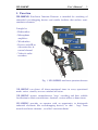
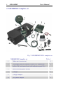
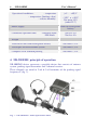
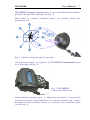
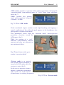
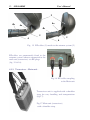
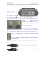
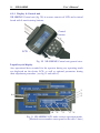
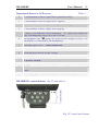
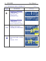
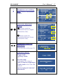
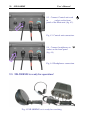
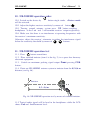
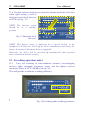
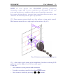
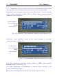
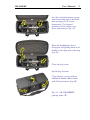
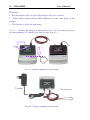
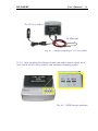
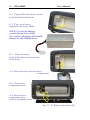
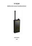
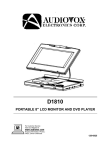
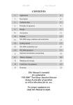
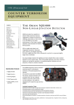
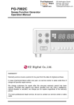
NR-900EMS
User’s Manual
CONTENTS
1
Function
3
2
NR-900EMS complete set
4
3
Main technical characteristics
5
4
NR-900EMS principle of operation
6
System design
10
4.1.1
Antenna system
11
4.1.2
Transceiver – Main unit
12
4.1.3
Display & Control unit
14
4.1.4
NR-900EMS User’s interface
16
NR-900EMS operational modes
19
4.2.1
«Listen» mode
19
4.2.2
«300» mode
20
4.2.3
«20К» mode
22
4.2.4
«Sleep» mode
23
4.2.5
Optional settings
23
NR-900EMS Power supply
24
5
NR-900EMS Marking
25
6
Sealing
26
7
Packing
26
8
Operation condition and restrictions
28
9
NR-900EMS preparation for use
29
4.1
4.2
4.3
2
NR-900EMS
User’s Manual
10
NR-900EMS operation order
31
11
NR-900EMS operation test
31
12
Searching operation order
32
13
Operation termination and packing
35
14
Battery charging
38
15
Rechargeable battery replacement
43
16
Shipping and storage
45
This Manual is intended
for explanation
“NR-900EMS”Non-linear Junction Detector
design & principle of operation
as well as directions for its use.
For proper equipment use,
study this Manual in depth.
NR-900EMS
User’s Manual
3
1. Function
NR-900EMS Non-linear Junction Detector is intended for searching of
concealed eavesdropping devices and similar facilities that enclose semiconductor elements.
It might be:
− Radio-mikes
− Microphone
amplifiers
− Wired mikes
− Devices with IR or
ultrasonic data &
control channel
− Video & audio
recorders
Fig. 1 NR-900EMS non-linear junction detector
NR-900EMS can detect all above-mentioned items in every operational
mode: active, stand-by or even switched off status.
NR-900EMS ensures comprehensive ‘bugs’ searching and their reliable
localization in fabric constructions, furniture, various office or home items.
NR-900EMS provides an operator with an opportunity to distinguish
industrial electronic like eavesdropping devices, in shot - ‘bugs’ from
natural non-linear elements , so called ‘corrosion diodes’
4
NR-900EMS
User’s Manual
2. NR-900EMS Complete set
2
1
9
3
2a
5
2c
4
2b
10
8
7
6
Fig. 2 NR-900EMS NLJD -complete set
NR-900EMS Complete set
Table 1
1
Main unit (transceiver)
1
2
Telescopic rod with antenna system (2a), connection
cables (2b) and control unit with indication panel (2c)
1
3
Built-in rechargeable battery
1
4
Charger
1
5
Charger adapter
1
6
AC power adapter
1
NR-900EMS
5
User’s Manual
7
Car adapter
1
8
Imitator
1
9
Headphones
1
10
Standard packing
1
User’s manual
1
Main unit (transceiver)
1
3. Main technical characteristics
Table 2
Probing signal frequency
848 MHz
Probing signal average power
0.2 W
Transmitter output adjustment
One step - 9 dB
Receiver sensitivity under 6dB s/n ratio
Not worse then
minus 138 dB/W
Receiver dynamic range
Not less 40 dB
Standard imitator detection range *
(under high transmitter output & maximum
receiver sensitivity)
Receiver input attenuation
Antenna power gain
Polarization
0, -10, -20,
-30, -40, -50
- transmitter antenna
- receiver antenna
- ellipticity
Directional diagram back-lobe level
(transmitter & receiver antennas)
Indication:
Not less 1 м
Not less 6 dB
Not less 8 dB
Circular,
not less 0,8
Not more
-15 dB
- visual
- audio
LCD
Headphones
6
NR-900EMS
User’s Manual
Operational conditions:
– temperature
– temperature (limiting value)
– relative humidity
Power supply
Continuous operation time:
(+5 … +40)°С
– 20°С и +50°С
Not more 85%
(under25°С)
Built-in rechargeable
battery
-searching mode
-20К mode
Not less 8 h
Not less 4 h
Weight
Transceiver unit with rechargeable battery
Not more 2,5 кг
Telescopic rod with antenna system
Not more 1,5 кг
Complete set in standard packing
Not more 7,5 кг
4. NR-900EMS principle of operation
NR-900EMS device represents a portable device that consists of antenna
system, probing signal transmitter and 2-channel receiver.
These channels are tuned to 2-nd & 3-rd harmonics of the probing signal
frequency F (fig. 3).
F0
2F0
3F0
Fig. 3 NR-900EMS. Main operational units.
NR-900EMS
User’s Manual
7
NR-900EMS Antenna system consist of two coaxial directional antennas
placed on the tip of the telescopic rod (fig. 4).
Main lobes of antennas radiation pattern are oriented along their
geometrical axis.
2F
3F
F
Fig. 4 Antenna system principal of operation.
All operational modes are adjusted by NR-900EMS Control unit placed
on a telescopic rod (fig. 5).
Fig. 5 NR-900EMS
Control unit. Main view.
Mono-harmonic probing signal ‘F’ emitted by transmitter is converted by
non-linear elements (semi-conductors) of a certain electronic unit to polyharmonic one and re-radiated (better say ‘scattered’) into an ambient space
(see also fig. 4).
8
NR-900EMS
User’s Manual
Two channel receiver detects the 2-nd & the 3-rd harmonics of the probing
signal from that received re-radiated signal.
2F & 3F received signal levels are displayed on the LCD screen.
Furthermore, at the same time tonal acoustic signal is reproduced by the
headphones. The tonal signal level corresponds to that of the received
electric signals.
By the way, contact spot of two metallic surfaces divided by oxide layer
produces a similar non-linear phenomenon, like ‘natural’ semi-conductors,
so-called, ‘corrosion diodes’.
But when irradiated by a probing signal of a certain frequency F it produces
and re-radiates, in general, it’s 3-rd harmonic unlike industrial semiconductors with their 2-nd harmonic reply.
This difference is widely used for target recognition in NLJD technique.
Special ‘20K-mode’ is used for painstaking received signal investigation.
This mode allows operator to distinguish with sufficient confidence between
industrial semi-conductors and the so-called ‘corrosion diodes’ – natural
semi-conductors produced by two metallic surfaces divided by thin oxide
layer.
The following operating modes are available for NR-900EMS User:
«300», «20К», «Listen» and «Sleep».
«300» mode represents the main operational mode.
In that case the received signal parameters are analyzed and displayed on a
LCD screen (fig. 6).
Fig. 6 NR-900EMS LCD in a
«300» mode
At that, continuous audio signal can be heard in the headphones. Its
loudness corresponds to the received radio signal level: 2-nd or 3-rd
harmonic, depending on operator choice.
Probing signal level adjustment as well as receiver input attenuation are also
available.
NR-900EMS
User’s Manual
9
«20К» mode provides an operator with a perfect opportunity to distinguish
‘corrosion diodes’ from industrial ones, i.e. ‘false’ alarm from electronic
items (fig. 7).
«20К» signifies that probing
signal pulse repetition frequency
is around ~ 20 kHz.
Fig.7 LCD in «20К» mode
Under mechanical impact (another words, light knocking and tapping) a
typical modulation of the reflected signal appears in the headphones that
corresponds to rhythm of an impact.
That phenomena results from the ‘corrosion diode’ electro-physical
parameters alteration caused by
A/M impact (fig.8).
While the reaction of a ‘real’,
industrial semi-conductor remains
constant and clear not subjected to
any mechanical effect.
Fig.8 Typical items with a great
number ‘corrosion diodes’
«Listen» mode is an optional
one. Probing signal transmitter is
turned off in this mode while the
receiver is active (fig.9).
In this case an operator obtains a
chance to check the environment
and to make sure of the absence
of interference at working frequencies.
Fig.9 LCD in «Listen» mode
10
NR-900EMS
User’s Manual
«Sleep» mode is a, so-called,
service-mode (fig. 10).
It is intended for the device
prompt revival after short
interruption in search operation .
Fig.10 LCD in «Sleep» mode
NR-900EMS is power supplied by dedicated built-in Li-Ion rechargeable
battery (7.4 V/ 4200mAh). Use standard Charger unit (supplied) for battery
charging.
The use of other chargers is strictly forbidden.
4.1. System design
NR-900EMS device consists of the Main unit - transceiver (1), antenna
system (2),
Control unit with LCD (3),
telescopic rod (4),
HF-cables (5) and headphones (6) (fig. 11).
6
1
2
4a
4
4b
5
Fig. 11 NR-900EMS design
3
4c
NR-900EMS
User’s Manual
11
4.1.1 Antenna system
4b
4а
С
В
А
Fig. 12 Antenna tilt adjustment. 4а – Joint fix screw
NR-900EMS antenna system is fasten to the tip of 3-elbow telescopic rod
(fig. 11). Antenna system elevation can fixes in a wanted position by a joint
with a holder screw (item 4а at the fig. 11 & 12).
Telescopic rod length can be adjusted by means of 2 level-locks (item 4b at
the fig.13).
4а
4а
Fig. 13 Telescopic rod length adjustment
4
4с
5
RF-cables (5) protected by
flexible plastic hose are
squeezed
through
the
telescopic rod (fig. 14).
Fig. 14 RF-cables pass through
the telescopic rod.
12
NR-900EMS
User’s Manual
2
4b
4a
4a
4b
5
5
4
4
Fig. 15 RF-cables (5) match to the antenna system (2)
RF-cables are permanently fixed to the
antenna system, whereas connected to the
mail unit (transceiver) via RF-plugs
(fig. 15 & 16).
4.1.2. Transceiver - Main unit -
Fig.16 HF-cables coupling
to the Main unit
Transceiver unit is supplied with a shoulder
strap for easy handling and transportation
(fig.17).
Fig.17 Main unit (transceiver)
with a shoulder strap.
NR-900EMS
User’s Manual
13
Main unit front panel with basic system connectors (fig.18):
Fig. 18 Front panel with
basic connectors
1 - Headphones jack
2 - Control unit jack
1
2
4
3
NOTE 1: The same jack is used for charging built-in rechargeable battery.
NOTE 2:
Coupling the device’s
Control unit or standard Charger to
that particular jack pay special
attention to the ‘key’ of the jack (see
an arrow at the fig. 19).
Fig. 19 ‘Key’ position in Headphone
and Control unit/Charger connectors
3…4 - Connectors for coupling antenna system RF-cables (see also fig. 16).
Fig.19-1 Dashboard socket for coupling transmitter’s antenna
cable to the main unit.
Fig.19-2 Dashboard socket for coupling receiver’s antenna cable
to the main unit.
NOTE: Optional color jack marking (Fig. 18, pos. 3 & 4) is available.
Fig.19-3 Transmitter’s antenna cable plug.
Fig.19-4 Receiver’s antenna cable plug.
14
NR-900EMS
User’s Manual
4.1.3. Display & Control unit
NR-900EMS Control unit (fig. 20) in essence consists of LCD and a control
board with 9 non-fastening buttons.
Control
buttons
LCD
Fig. 20 NR-900EMS Control unit general view.
Liquid-crystal display
Any operational data essential for the operator during any operating mode
are displayed on the device LCD, as well as optional parameters during
their adjustment procedure. (see fig 21 and table 4).
13
14
10
11
6
12
9
5
3
7
1
2
4
8
Fig. 21 NR-900EMS LCD under various operation modes.
(Marked screen numbers correspond to the table 3 lines)
NR-900EMS
User’s Manual
Operational data on a LCD screen
15
Table 3
1
2-nd harmonic relative-signal level (pseudo-analog)
2
2-nd harmonic relative-signal level (digital)
3
3-rd harmonic relative-signal level (pseudo-analog)
4
3-rd harmonic relative-signal level (digital)
5
2-nd & 3-rd harmonic value difference. ‘ +’ (plus) icon stands for
the 2-nd harmonic excess over the 3-rd one.
Headphones icon
points out what receiver output (2-nd or 3-rd
harmonic) is connected to the headphones.
6
7
Probing signal level - Pmax/Pmin/Poff
8
Actual attenuator value: -10, -20, -30, -40, -50 dB
9
Rechargeable battery acting voltage
10
20К mode
11
LISTEN MODE
12
Sleep MODE
13
LCD contrast adjustment and its numerical value in conventional
units.
14
«Averaging –out constant» adjustment and its acting value .
Control buttons
NR-900EMS control buttons (fig. 22 and table 4):
Fig. 22 Control unit buttons
16
NR-900EMS
User’s Manual
4.1.4. NR-900EMS USER’S INTERFACE
Buttons
symbol
NR-900 EMS
The device is switched off:
- Single stroke:
→ «Listen» mode
-Second stroke:
→ «Search» mode
The device is switched on:
- Single stroke:
→ Switching off without
operator’ adjustment storage
PWR
300
20К
Probing signal output
switching over (Pmax/Pmin)
Operational mode switching
over
«Search» / 20 К
Table 4
LCD data
NR-900EMS
3
2
User’s Manual
17
Headphones out switching
over (2-nd or 3-rd harmonic
output)
Attenuator adjustment
buttons
Button stands for
attenuation increase (higher
attenuation value)
Button stands for
attenuation decrease (lower
attenuation value)
Headphones audio level
adjustment.
( See the note on the page 18)
Functional button.
Single stroke
→«Sleep» mode
∗
Second stroke
in less then 20 c interval :
→ LCD contrast adjustment.
Triple stroke in less then 20 c
interval :
→‘Averaging-out constant’
adjustment.
-32 dB
0 dB
18
NR-900EMS
NOTE to the Table 4
User’s Manual
‘VOLUME
CONTROL’
Headphones volume control is available only in the main operational
modes: «LISTEN», «300» or «20К».
Volume control is not provided in optional operational modes (LCD
contrast & ’Averaging-out constant’ adjustment and etc.).
Volume control is carried out by ‘’и
‘’ buttons:
- Press any of A/M buttons – a new window (with headphone icon,
pseudo-analog
scale
and
adjusted volume level in dB )
will appear on LCD (fig. 22a).
‘0 dB’ corresponds to maximum
audio level in the headphones,
while ‘-32dB’ - to its minimum.
Volume adjustment step - 2dB.
Fig. 22а Headphones volume control
adjustment scale
- Press ‘’ or ‘’ button to adjust the right audio signal level in the
headphones and release the button.
- NR-900EMS will return to the previous operational mode automatically
with a corresponding audio level alteration in the headphones.
At that (after ‘volume control’ button release) the main operational mode
window appears on the LCD.
Note: the adjusted audio level will be stored in a device nonvolatile memory
till the next volume control adjustment.
‘’ or ‘’ button has an auto-repeat facility.
If one press-and-hold ‘’ or ‘’ button – only graphic representation in
the window is altered.
Please note: the audio level alteration in the headphones is carried out
several seconds after ‘’ or ‘’ button was released and is confirmed
by a shot audio signal.
NR-900EMS
User’s Manual
19
4.2. NR-900EMS operation modes
4.2.1. «Listen» mode
After switching on the device using
button the «Listen» mode get
active. The following initial data are displayed on LCD screen (fig. 23):
1– Transmitter is switched off .
2– Receiver is active (in the ‘Listen’ mode);
3– Headphones are connected to the 2-nd harmonic output.
4– Attenuator is in -10 dB mode;
5– The ‘Averaging-over constant’ data corresponds to the value that was
adjusted during the last operation and stored in the device memory.
3
2
4
1
5
Fig. 23 NR-900EMS LCD view after switching on the device .
Headphones volume control is in the state that was adjusted during the last
operation.
The device transmitter is off-state in this mode while its receiver is active.
This mode allows operator to control and evaluate an interference level at
the operating frequencies.
Moreover, the following adjustments are available for an operator:
− Headphones switching over amongst the 2-nd & 3-rd harmonica outputs
( 3/2 button).
− Input signal attenuation adjustment (
- Headphones volume control (
buttons);
buttons).
20
NR-900EMS
User’s Manual
4.2.2. «300» mode
button repeated stroke activates NR-900EMS main operating mode
‘300’ (‘searching’).
At that the following working parameters are set on default (fig. 24):
− Minimum probing signal output level (Рmin);
− -10 dB input signal attenuation (АТТ= -10 dB);
− Headphones are coupled to the 2-nd harmonic output.
8
2
1
3
6
5
7
4
Fig 24 LCD in a «300» mode:
1234-
LCD lines that corresponds to the 2-nd & 3-rd harmonic signal.
Relative 2-nd & 3-rd harmonic level in dB in pseudo-analog form.
The same in digital form.
2-nd and 3-rd harmonic level difference in dB (see fig.25) .
+ (plus) stands for 2-nd harmonic level excess over the 3-rd one;
5- Probing signal output conventional value Р max/P min (see fig.26).
6- Attenuator acting value for the received signals (see fig.27).
7- Built-in battery effective voltage at the present situation.
NOTE: After battery discharge below 5,7 V a typical melody warning
signal can be heard in the headphones accompanied by the words
BATTERY EMPTY on LCD screen. In this case charge the battery
as soon as possible.
8- Headphones coupling indication to the 2-nd or 3-rd harmonic output
accordingly (see fig. 28).
NR-900EMS
User’s Manual
21
Fig.25 2-nd and 3-rd harmonic
level difference ,
for instance, 17 – 3= +14 dB
Fig.26 Probing signal output
level, adjusted by PWR button
Fig. 27 Acting attenuation
value 0,-10, -20, -30, -40,
-50 adjusted by
buttons.
Fig. 28 Indication of
headphones coupling
to the 2-nd or 3-rd
harmonic output.
22
NR-900EMS
User’s Manual
In «300» mode the following settings are available for the operator:
−
Headphones switching over among the 2-nd & 3-rd harmonic
outputs (3/2 button).
−
Input signal attenuation adjustment (
−
Headphones volume control (
buttons);
buttons).
4.2.3. «20К» mode
«20К» mode can be activated by 300/20К button.
Received signal level value is not displayed in this mode (fig.29).
Probing signal output level adjustment is not available in this mode.
Fig. 29 LCD in «20К» mode
In «20K» mode the following adjustments are available for the operator:
− Headphones switching among the 2-nd & 3-rd harmonic (3/2 button).
− Input signal attenuation adjustment (
buttons);
- Headphones volume control (
buttons).
Repeated 300/20К button stroke restores the «300» mode.
NR-900EMS
User’s Manual
23
4.2.4. «Sleep» mode
*
«Sleep» mode is activated by a single stroke of
button.
In this mode, the device switches off automatically after 20 sec. of the mode
activation. All working parameters settled by an operator are stored in a
device nonvolatile memory (fig.
30).
«Sleep» mode is intended for
the rapid restoration of the
device operational
facility
(after its short break up in a
searching operation).
Fig. 30 «Sleep» mode indication
After the device repeated switching on by
button it returns into an
active mode with all adjustments restored .
NOTE: If NR-900EMS switching off was done by
button (passing
«Sleep» mode) the «Listen» mode with every initial factory setting would
be restored after device activation.
4.2.5. Optional settings
*
Successive
button press within A/M time lapse allows an operator to
proceed to the following ‘optional settings’.
LCD Contract adjustment
*
button stroke activates LCD
contrast adjustment. At that
LCD-contrast analogue scale
appears on the screen together
with its certain numerical value
evaluated in some conventional units (fig. 31).
Fig.31 LCD-contrast scale
Display contrast setting can be done by
and is available only from this menu page.
buttons
24
NR-900EMS
User’s Manual
’Averaging-out constant’ adjustment
*
The next
- keystroke
switch LCD into the mode of
so-called
‘averaging-out
constant’
adjustment
(for
received 2-nd & 3-rd harmonic
signals).
The words «AVERAGE
CONSTANT» appears on the
screen with its numerical value,
beneath the line (fig. 32)
Fig. 32 ‘Averaging-out constant’ adjustment
Available ‘averaging-out constant’ value is as follows: 1, 2, 4, 8, 16.
The higher the ‘averaging-out constant’ value – the lower the noise in an
output signal, while the device reaction get more inertial.
The ‘averaging-out constant’ value is adjusted by the operator to the current
searching process by means of
buttons.
The chosen ‘constant’ value is stored in a device nonvolatile memory and
automatically restored later-on until an operator will alter it.
*
The next
- keystroke returns the device to an operational mode from
which all these manipulations were started.
NOTE: In spite of various menu pages displayed on LCD screen the device
continues to operate in the mode when the menu review was started.
After all menu pages were run over LCD goes back to the first one.
4.3. NR-900EMS Power supply
NR-900EMS is power supplied from built-in Li-Ion rechargeable battery.
NOTE: Flat battery status (lower then 5.7 V) is indicated by a typical
melody in the headphones, while 'BATTERY EMPTY’ warning appears
in that display line.
In that case switch-off the device immediately and charge the battery by
means of Standard charger (supplied).
Otherwise, the device will be switched off automatically after repeated
above-mentioned melody warning.
NR-900EMS
User’s Manual
25
5. NR 900EMS Marking
Main unit - transceiver
Works number
Fig. 33
Works
number on the back
side of the Main unit
body.
1
2
Fig. 34 NR-900EMS front panel marking: Manufacturer Logo (1) and
“NR 900EMS” sign (2).
Fig. 35 Full LOGO on the Main
unit sidewalls
26
NR-900EMS
User’s Manual
Packing bag
Fig.36 The NR-900EMS
reference sign and its works
number are on a label in a pocket
of the packing bag.
Label
6. Sealing
Main unit - transceiver
Works sealing: bottom-right hollow for a fastening screw on the front side
of the Main body (fig. 37).
Fig. 37 Works sealing of Main unit body.
7. Packing
Complete set of NR-900EMS equipment is
packed into a dedicated shockproof bag
(fig.38). The bag is made of a durable
synthetic fabric, has rigid frame and soft
inserts. Handy grips and a shoulder strap
make its transportation easy and
comfortable.
Fig.38 NR-900EMS standard packing bag.
NR-900EMS
User’s Manual
27
NR-900EMS Placement in a standard packing bag is shown on fig. 39, 40.
6
5
1
2
3
4
Fig. 39 NR-900EMS placement in a packing bag
1.
2.
3.
4.
5.
6.
Standard packing bag
Main unit - transceiver
Telescopic rod with Antenna system and Control unit.
Headphones
Pocket for appliances.
Pocket for technical documentation.
Fig. 40 NR-900EMS appliances
in dedicated pocket
a - Charger with adapters and
cables.
b - Imitator
1
2
28
NR-900EMS
User’s Manual
8. Operation condition and restrictions
After long-term exposure to a low temperature keep the device packed in a
standard carrying case at least 2 hours for evening up its temperature with
the environment.
Operating NR-900EMS keep corresponding safety measures: safety
precautions for the open RF emitters:
-
Don't direct the NR-900EMS aerial to the human eyes from the
distance less then one meter.
-
Avoid prolonged presence of personnel in a main lobe of NR-900EMS
antenna’ diagram.
NOTE: Probing signal power density at the distance of 1 meter at the
maximum of the directional radiation pattern does not exceed Russian
State Standard 12.1.006-84 (Russian State Sanitary Norm) for UHF
equipment serviceman under of continuous 8-hours operation.
29
NR-900EMS
User’s Manual
9. NR-900EMS preparation for use.
9.1. Take NR-900EMS out of standard packing bag (fig. 41).
Fig. 41 NR-900EMS unpacking
9.2. Couple two HF-connectors
to corresponding jacks on the Main unit front
panel using mnemonic symbols and/or color
marks as a reference (fig. 42).
Рис. 42
Подключение
антенных кабелей
30
NR-900EMS
User’s Manual
9.3. Connect Control unit cord
to
socket on the front
panel of the Main unit (fig. 43).
Fig. 43 Control unit connection.
9.4. Connect headphones to
socket on the front panel
(fig. 44).
Fig. 44 Headphones connection.
9.5. NR-900EMS is ready for operation!
Fig. 45 NR 900EMS set is ready for searching.
NR-900EMS
User’s Manual
31
10. NR-900EMS operation order
10.1. Switch on the device by
button single stroke. «Listen» mode
will be activated.
10.2. Adjust the highest receiver sensitivity by means of button
.
10.3. Turning around antenna system press 2/3 button coupling
headphones to the 2-nd and 3-rd harmonic receiver’ output respectively.
10.4. Make sure that there is no interference at operating frequencies with
the receiver’s maximum sensitivity.
Otherwise, adjust the receiver’ attenuator to reduce the interference signal
below the sensitivity threshold by means of
buttons.
11. NR-900EMS operation test
11.1. Press
button second time.
11.2. Place standard imitator (item 8 at the fig. 2) in a space free from any
electronic equipment.
11.3. Switch on maximum probing signal output Pmax pressing PWR
button .
11.4. Point out NR-900EMS antenna system to imitator from the 0,5-0,6 m
distance (see fig. 46).
Imitator
0,5…0,6 m
Fig. 46 NR-900EMS operation test by means of standard imitator.
11.5 Typical audio signal will be head in the headphones while the LCD
shows 2-nd and 3-rd harmonic level.
32
NR-900EMS
User’s Manual
11.6. Gradual imitator moving away from the antenna main lobe will cause
audio signal muting as well as
displayed signal level decrease
on LCD (see fig. 47).
NOTE: The antenna system
should be in a standing
position
Fig. 47 Harmonic level
decrease.
NOTE: Flat battery status is indicated by a typical melody in the
headphones. In that case switch-off the device immediately and charge the
battery by means of Standard charger (supplied).
Otherwise, the device will be switched off automatically after repeated
above-mentioned melody warning.
12. Searching operation order
12.1. Carry out searching of semi-conductor elements (eavesdropping
devices) under maximum transmitter output and the highest receiver
sensitivity (Pmax & ATT = 00 dB at the fig. 48).
That will provide an ultimate searching efficiency.
Fig. 48 Searching mode working parameters
NR-900EMS
User’s Manual
33
NOTE: In every specific case NR-900EMS operating parameters
(transmitter output and receiver sensitivity) are determined by the real
noise and interference condition right on spot of searching operation.
In its turn, this interference is arisen from casual non-linear scatterer that
cannot be moved away from the place of operation.
12.2 Scan antenna system slowly over the surface or item under control.
Hold antenna main lobe at a right angle to that surface (fig. 49 ).
Fig. 49 Antenna system scanning diagram
12.3. After audio signal arising in the headphones, localize it referring LCD
indication and the highest level of that audio signal.
To do this:
− Alter antenna system position and orientation.
− Switch over probing signal level pushing PWR button;
− Alter receiver sensitivity pressing
buttons .
34
NR-900EMS
User’s Manual
12.4. Comparing the level of the 2-nd & the 3-rd harmonic evaluate their
ratio and draw the conclusion about the nature of the revealed object.
Significant 2-nd harmonic level excess over that of the 3-rd one (fig.50)
with a great probability testifies that an object under control contains
industrial semi- conductors
2-nd harmonic
level is higher
then
the 3-rd one
Fig. 50 ‘Industrial’ semi-conductor indication on the device LCD.
Otherwise most probable reason of the target response is so-called
‘corrosion diode’(see fig. 51).
3-rd harmonic
level is higher
then
the 2-nd one
Fig. 51 ‘Corrosion diode’ indication on the device LCD
12.5. For specifying searching results switch to ‘20K’ mode pushing
300/20k button ( see also fig. 29)
Use audio monitoring via headphones to control target reaction to the
outside mechanical impact.
Mostly that will help to determine the type of the target revealed.
NR-900EMS
User’s Manual
35
13. Operation termination and packing
13.1. Press
button to switch off the device
NOTE: If necessary, use “Sleep MODE”
and subsequent automatic device switch off
with operator’s favorite adjustments
storage.
13.2. Unplug headphones, Control unit
cord and HF-antenna cables from
the Main unit.
13.3. Push in telescopic rod (fig. 52)
and put antenna system into
shipping-storage position
(fig.53).
NOTE:
Pushing in the rod hold it
vertically with antenna system
up to prevent HF-cables
damage
Fig. 52
Telescopic rod pushin- in order
13.4. Put all units and accessories into packing bag.
Fig. 53 Telescopic rod with antenna system
adjusted for storage and transportation.
36
NR-900EMS
User’s Manual
NR-900EMS packing order.
Stow the device appliances
into corresponding pockets
of the transportation bag
and close their cover
(fig. 54).
Place the main unit
on the bottom of the bag
(fig. 55).
Fix the unit with an
appropriate belt and
Velcro-fastener (fig. 56).
Lay antenna HF-cables and
Control unit cord above the
Main unit body preventing
their small bending radius
(fig. 57).
Fig. 54 – 57 NR-900EMS
packing order (I).
NR-900EMS
User’s Manual
37
Lay the rod with antenna system
and control unit above the Main
unit arranging LCD screen
downwards. Use figured
partitions of the bag for your
better convenience (fig. 58)
Place the headphones above
telescopic rod putting them on its
handle in the right part of the bag
(fig. 59).
Close the bag cover.
Zip the bag fastener.
Clasp the bag’s straps with an
additional handle and fix them
with Velcro-fastener (fig. 60)
Fig. 58 – 60 NR-900EMS
packing order (II)
38
NR-900EMS
User’s Manual
14. Battery charging
Operating the Mach 1 FUSION LENMAR charger use its Manual
(supplied) as a reference.
Fig. 61 NR-900EMS standard charger complete set.
14.1. Standard charger complete set (fig. 61):
1 – Charger body
2 – Charging adapter (for coupling to the device Main body).
3 – AC adapter (LENMAR LAD1512DB2)
4 - 12 V car cable
NOTE: AC adapter LENMAR LAD1512DB2 allows to charge the battery
from the mains 100 – 240 V, 50/60 Hz.
NR-900EMS
User’s Manual
39
Latches
LED indicators
Front panel
Charger
Fig. 62 Charger, main view
Charger’s back side.
Socket for coupling AC
adapter or car cable.
Fig. 63 Charger body back side.
14.2. Battery charging order.
14.2.1. Couple charging adapter cable
to
socket on the Main body front
panel (fig. 64);
14.2.2. Couple charging adapter to the
charger itself (fig.65).
Fig. 64 Charger connection
to the Main body.
40
NR-900EMS
User’s Manual
To do that:
1. Put the adapter body on top of the charger and press it down.
2. Slide adapter body toward LED indicators on the front plate of the
charger.
3. The charger is ready for operation.
14.2.3. Connect the charger to the mains or to 12 V car socket by means
of corresponding AC adapter (fig. 66) or cable (fig. 67).
1
2
3
Fig. 65 Adapter coupling to the charger.
To mains
To main unit
Fig. 66 Charger coupling to the mains.
NR-900EMS
User’s Manual
41
To 12 V car socket
To Main unit
Fig. 67 Charger coupling to 12 V car socket.
14.2.4. After coupling the charger to main unit and to power supply net it
starts actual battery status analysis and automatic charging process.
Fig. 68 3 LED charger indicator
42
NR-900EMS
User’s Manual
14.2.5. Use 3 LED ‘MED – HI – MAX’ on the charger front panel as well
as table 5 as a reference to control battery charging (fig. 68).
Charger LED indications
Table 5
LED indication
Charging process status
Battery status analysis
Flat battery.
Charging start
MED
HI
MAX
red
dead
dead
successive green blinking
50 to 70% battery charge
green
successive green
blinking
Battery charge over 70%
green
green
Blinking
green
Fully charged battery
green
green
green
14.2.6. After battery charging completion unplug the charger from the
mains and adapter from the device.
NOTEе: The battery can be unplugged from the charger during any
charging stage without any failure to the battery or the charger itself.
Attention! The charger should be switched off from the mains before hand.
NR-900EMS
User’s Manual
43
15. Rechargeable battery replacement
Attention! Switch of the device and unplug the Control unit cord
before replacing the rechargeable battery.
In case of spent or dead battery it should be replaced by a new one provided
by the device manufacturer/ supplier.
Turn off two screws on the
backside of the Main unit
body.
Open the back side cover
Draw the battery from
the battery compartment.
Fig. 69 – 71
Battery replacement (I)
44
NR-900EMS
User’s Manual
15.1. Unplug old battery from a socket
on the backside of the device.
15.2. Take a new battery
supplied by the device OEM .
NOTE! Use only the batteries
provided by the device OEM.
Any ‘similar’ substitute will inevitably
damage the NR-900EMS device
15.3. Plug new battery
to the A/M socket on the back side
of the device.
15.4. Place the battery into the battery
compartment.
15.5. Close battery
compartment cover.
15.6. Fasten battery
compartment cover
with corresponding screws.
Fig. 72 - 75 Battery replacement (II)
NR-900EMS
User’s Manual
45
16. Shipping and storage
NR-900EMS can be shipped in standard packing in a passenger cabin by
any kind of transport.
Prevent the device in standard packing from shock and vibration.
Store packed device under the temperature from 5 up to 40°C and relative
humidity no more then 80 % at 25°C
Rechargeable batteries should be stored in charged state.
46
NR-900EMS
User’s Manual
FOR NOTES
_________________________________
_________________________________
_________________________________
_________________________________
_________________________________
_________________________________
_________________________________
_________________________________
_________________________________
_________________________________
_________________________________
_________________________________
_________________________________
_________________________________