1
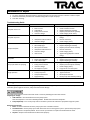
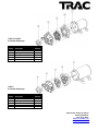
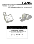
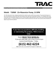
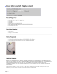
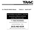
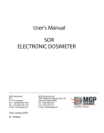
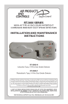
INSTALLATION AND MAINTENANCE INSTRUCTIONS For Models: T10071 T10072 T10073 T10077 12V DIAPHRAGM PUMPS Water System Pump, 3.3 GPM, 35 PSI Washdown Pump, 4.5 GPM, 40 PSI Washdown Pump, 2.9 GPM, 60 PSI Washdown Pump, 5.3 GPM, 70 PSI If you have any questions, difficulty installing or maintaining this product, TRAC is here to help! First READ THIS MANUAL. If you still need help, call us from 9 am to 4 pm (central time) Monday – Friday. (615) 462-6224 Note: At this time, we provide Phone Support in English only. INSTALLATION AND MAINTENANCE INSTRUCTIONS 12V DIAPHRAGM PUMPS Instructions for Assembly, Testing, Operation, Servicing, and Storage Please read and save these instructions. Read carefully before attempting to assemble, install, operate or maintain this pump. Protect yourself and others by observing all safety information. Failure to comply with instructions could result in personal injury and/or property damage! Retain instructions for future reference. Unpacking - When unpacking, inspect carefully for any damage that may have occurred during transit. Make sure the pump is correctly installed before putting unit into service. READ and UNDERSTAND the Owner's Manual completely before using this Pump. Assemble, test, and use only in accordance with this Owner's Manual instructions. DO NOT TURN ON POWER to pump until ready to spray in order to avoid unintentional spray release. Improper use of the pump could result in serious injury to the operator or nearby persons/animals, or could cause damage to the environment. Summary of Important Information Listed below is a summary of safety information of particular importance. DURING ASSEMBLY EXERCISE CAUTION when attaching the ON/OFF switch (not included) to battery terminals. Follow the steps listed in the Assembly section of this manual in exact sequence when connecting the pump to battery terminals. Caution must be exercised to avoid contact with battery acid and to prevent sparking. CHECK and TEST completed assembly as directed in this manual. DO NOT MODIFY pump design Installation STEP ONE: Mounting This pump is self-priming. The pump should be located in an area that is dry and provides ventilation. DO NOT locate the motor near low temperature plastics or combustible material. The surface temperature of the motor may exceed 121℃. The pump may be mounted in any position. However, if mounting the pump vertically the pump head should be in the down position so that in the unlikely event of a leak, fluid will not enter the motor. Secure the rubber feet with appropriate fasteners. DO NOT compress the feet, doing so will reduce their ability to isolate vibration and noise. STEP TWO: Connect pump to input and output hoses Sealers and Teflon tape may act as lubricant causing cracked housings or stripped threads due to over tightening. Care should be used when applying sealers; it may enter the pump inhibiting valve action, causing no prime or no shut-off. Failures due to foreign debris are not covered under the warranty. STEP THREE: Connect pump to battery or 12V supply ! Batteries are hazardous because they contain caustic acid and can emit explosive gases. Caution must be exercised when making connections to a battery to avoid shock and contact with acid and to prevent any sparking that could lead to an explosion. ALWAYS follow the safety instructions and steps listed below in exact sequence when connecting the pump to the battery terminals. The pump should be on a dedicated (individual) circuit, controlled with an ON/OFF switch rated at or above the fuse amp rating indicated by the pump motor label. For the pump to meet European CE requirements the circuit must be protected with a slow blow fuse or equivalent circuit breaker. Use 14 AWG wire or larger. Connect the pump to battery using the following procedure: 1. Disconnect the boat’s battery ground wire. 2. Connect the pump's red wire to the positive (+) terminal of the battery. 3. Connect the pump's black wire to the negative (-) terminal of the battery. 4. Reconnect the boat’s battery ground wire Note: Skip steps (1) and (4) if battery is not in a boat or vehicle. WARNING: Always connect in this sequence to avoid possible shock. STEP FOUR: Check and test completed assembly ! Check assembly to assure the pump is properly assembled and in safe working condition. Test the system for leaks. 1. If a holding tank is used, fill the tank with water. 2. If the pump is an “on demand” pump, when turned on, the pump will prime itself then turn off once reaching pressure. When the flow continues, the pump will automatically re-start. 3. Check for leaks throughout the system. If a leak is detected, fix the leak and re-test the system. Operation/Using the Pump Pressure switch operation The pressure switch (on the end of the pump) reacts to outlet pressure and interrupts power at the shut-off pressure indicated on the pump label. When outlet pressure drops below a predetermined limit, the switch will turn the pump ON and run until the shut-off pressure is achieved. The shut-off pressure is set to factory calibrated standards. Note: If the plumbing is restrictive or the flow rate is very slow, the Pump may re-pressurize the outlet faster than the fluid is being released, causing rapid cycling (ON/OFF within 2 seconds). If the pump is subjected to rapid cycling during normal operation, or for infrequent period, damage may occur. Applications which exhibit rapid cycling should have restrictions in the outlet eliminated or minimized. Discontinue use if clogged or inoperative. If the pump must be left unattended at any time: 1. Disconnect power to the pump 2. Relieve system pressure Maintenance or Repair 1. 2. 3. To service the pump, disconnect power to the pump and be sure all system pressure is relieved. Perform repairs. Follow the directions provided in the troubleshooting table to repair the pump. Test after servicing. Troubleshooting Guide PROBLEM Pump will not turn on CAUSE Bad electrical connection Short in wires Locked drive Faulty pressure switch Incorrect voltage Inlet air leak Pump will not prime Low pressure/flow Pump leaks Pump cycles while not spraying Rough operation Inlet/Outlet rube restriction Incorrect voltage Worn wobble plate Worn diaphragm Worn pressure switch Inlet/Outlet tube restriction Incorrect voltage Inlet air leak Loose fasteners Pump seals degraded Leak in diaphragm Leak in the system Faulty pressure switch Incorrect voltage Air trapped in system Flexible mounting surface Loose pump head Compressed base feet Rigid plumbing SOLUTION Check battery connections Check condition of wires Replace diaphragm assembly Replace pressure switch assembly Check voltage (12vdc ±10%) Tighten fittings/Replace cracked fittings Remove restriction Check voltage (±10%) Replace diaphragm assembly Replace diaphragm assembly Replace pressure switch assembly Remove restriction Check voltage (±10%) Tighten fittings/Replace cracked fittings Tighten fasteners Replace pump head assembly Replace diaphragm assembly Tighten leaking hose clamps/fittings Replace pressure switch assembly Check voltage (±10%) Purge the air from the system Mount pump on rigid surface Tighten fasteners Decompress base feet Plumb pump with flexible plumbing Storage Prepare the pump for end-of-season storage by running RV antifreeze through the system. This will keep internal parts lubricated, protect against corrosion, and protect from freeze damage. Pump will be damaged if it freezes with water inside. Protect by following the instructions below: Preparing for storage 1. Add antifreeze – Pour RV antifreeze into the pump system. Note: RV antifreeze is non-toxic and biodegradable. DO NOT USE automotive antifreeze. 2. Run pump briefly – Turn on the pump and run the water system until antifreeze is pumped through the system. Removing from storage 1. Drain – Drain the antifreeze left in the pump system into a suitable container. 2. Flush with water – Fill the pump system with fresh water and run through the system. Operate the pump system until the system is completely flushed. Be sure to set up containers to capture the antifreeze flush water. 3. Disposal – Dispose of the antifreeze and flush water properly. TRAC Diaphragm Pump Limited Warranty This limited warranty is provided by TRAC Outdoor Products Co (TRAC) to the original consumer purchaser (purchaser) of the TRAC Pump. This limited warranty is not transferable to any other party. TRAC will at its option repair or replace any part(s) of the TRAC Pump which may be found by TRAC to be defective within three (3) years of purchase. TRAC will pay the shipping cost to the purchaser for any part(s) which may be shipped by TRAC. For warranty repair or replacement, the purchaser must provide dated proof of purchase and notify TRAC of the request for warranty service. The purchaser will notify TRAC by email at [email protected] or by phone at 615-462-6224 for warranty service. TRAC will attempt to provide parts needed to repair the pump. If the pump is to be returned, purchaser will be provided a Return Goods Authorization (RGA) to include with any return for warranty service which will be shipped at the purchaser’s expense to the address provided. The purchaser must use reasonable care in maintenance and operation of the product in accordance with this manual. Failure to follow the instructions in the manual will void the warranty. This warranty covers defects in material or workmanship of the TRAC pump. This warranty does not cover failure that results from misuse, improper installation, accident, abuse, neglect, modification, or improper maintenance. There is no other express warranty. Implied warranties, including those of merchantability and fitness for a particular purpose, are limited to one (1) year from the date of purchase. Any damage to watercraft resulting from proper or improper use of this TRAC pump is not covered under this warranty. Costs of installation or repair by service centers or marine repair facilities are not covered by this warranty. This is the exclusive remedy and any liability for any and all incidental or consequential damages or expenses whatsoever is excluded. Some states do not allow limitations on how long an implied warranty lasts, or do not allow exclusion or limitation of incidental or consequential damages, the above limitations may not apply to you. This limited warranty gives you specific legal rights, and you may also have other rights which vary from state to state. PARTS If ordering a part, provide the pump model number as well as the part item number shown. T10071 & T10072 4-Chamber Diaphragm Item Number 1 2 3 4 5 6 7 8 9 10 11 12 13 14 15 Description Motor assembly Cam/Bearing with set screw Piston, Outer Bearing Cover Diaphragm Piston, inner Valve Housing O-ring Fitting (1/2” thread male fitting/12.5mm hose barb) Pump housing Pressure switch Pump screw Check valve Motor screw Cam/Bearing Set Screw Quantity 1 2 4 1 4 4 1 1 2 1 1 1 4 1 1 T10077 & T10074 5-Chamber Diaphragm Item Number 1 2 3 4 5 Description Motor assembly Diaphragm assembly Valve plate assembly Pump head assembly Pressure switch assembly Quantity 1 1 1 1 1 T10073 3-Chamber Diaphragm Item Number 1 2 3 4 5 Description Motor assembly Diaphragm assembly Valve plate assembly Pump head assembly Pressure switch assembly Quantity 1 1 1 1 1 TRAC Outdoor Products Company 251A Mayfield Drive Smyrna, TN 37167 www.trac-outdoor.com [email protected] 615/462-6224