1
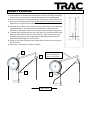
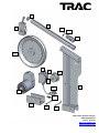
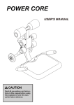
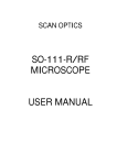
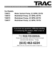
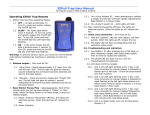
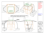
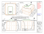
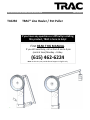
INSTALLATION AND OPERATING INSTRUCTIONS T10250 LINE HAULER TRAC® Line Hauler / Pot Puller If you have any questions or difficulty installing this product, TRAC is here to help! First READ THIS MANUAL. If you still need help, call us from 9 am to 4 pm (central time) Monday – Friday. (615) 462-6224 Note: At this time, we provide Phone Support in English only. INSTALLATION AND OPERATING INSTRUCTIONS LINE HAULER Please read and save these instructions. Read carefully before attempting to assemble, install, operate or maintain the product described. Protect yourself and others by observing all safety information. Failure to comply with instructions could result in personal injury and/or property damage! Retain instructions for future reference. Unpacking - When unpacking, inspect carefully for any damage that may have occurred during transit. Make sure any loose fittings, bolts, etc., are tightened before putting unit into service. SPECIFICATIONS Rated Line Pull: Motor: Output: Gear Reduction Ratio: Line Speed: Current: Power Cable: Mounting Bolt Pattern: Overall Dimensions: Net Weight: 110 lb. (49.9kg) 12v DC (Permanent Magnet) 300W 53:1 127-150 ft/min (39-46m/min) 3.4 (no-load) to 30 (stall) Amps 10 Gauge AWG, splice to 8 gauge wire for runs over 6 ft. (2 m) M8x45mm (alternative is 5/16” x 1-3/4” or length required for application) 23.6” L x 13” W x 8.7” H (60 x 33 x 22cm) 18.9 lb. (8.5kg) GENERAL SAFETY INFORMATION - Throughout this manual potential safety hazards will be noted with the following terms. Please read and understand these terms before operating the product. Warning indicates a potentially hazardous situation that COULD cause death or serious injury if the warning is ignored. Caution indicates a potentially hazardous situation that cause minor or moderate injury if the warning is ignored. It may also mean hazard that will only cause damage to property. This notation is also used to alert you against unsafe practices. MAY SAFETY ISSUES The TRAC® Line Hauler is a powerful piece of machinery. It is important that you understand the basics of its operation and specifications so that when you need to use it, you can use it with confidence and safety. In this manual is a list of components of your Line Hauler and their use. You should practice using your Line Hauler before you head to the water. USE CAUTION KEEP FINGERS AWAY FROM MOVING PARTS Do NOT exceed rated capacity shown above. Intermittent use only. Allow Line Hauler to cool between uses. Do NOT use Line Hauler to pull or move people in any way. Failure to heed these warnings may result in personal injury and/or property damage. Use gloves to protect hands when handling the rope. TRAC Line Hauler is designed and made for intermittent use and should not be used in constant duty applications. ASSEMBLY & MOUNTING 1. Drill 4 holes on the shipboard where you want to mount your TRAC Line Hauler, use the mount as a template and attach with supplied screws (M8x45mm). 2. Slide the Line Hauler in the mounting plate, locking it with a drop nose lock pin. 3. Insert arm into frame (hinge in first). Attach Arm Stop Screw into top of frame. Stop Screw is in bag with swivel pulley. 4. Strip ends of your battery wire and insert into the butt splices on the end of the supplied connector. Crimp butt splice to attached wire. Heat butt-splice insulation to seal to wire. Make sure red is positive (+) and black is negative (-). 5. To attach rope, feed the rope over the nylon wheel (1), around the lower inside pulley (2) and around the stainless rope wheel (3). From this point, you have the option of pulling the rope straight down or looping the rope around the lower double pulley again for more traction. 6. Pulling in your traps will require you to keep tension on the line and to pull the end of the rope. 7. Start motor. Put tension on rope, lift trap/pot. 3 1 Before routing rope, tilt Arm up and slide into frame. Insert lock pin. 2 4 ROPE PATH Batteries contain gases which are flammable and explosive. Wear eye protection during installation and remove all jewelry. Do not lean over battery while making connections. LINE HAULER ACCESSORIES YOU WILL NEED (not included) Gloves – for handling rope Rope – length according to your needs Battery Wire – from plug to battery Trap – type according to your needs MAINTENANCE 1. Periodically remove all dirt or corrosion and always keep clean and dry. 2. Do not attempt to disassemble the gear box. Email or call our customer service department at [email protected] or 615/462-6224. 3. The gearbox has been lubricated using a high temperature lithium grease and is sealed at the factory. No internal lubrication is required. TROUBLESHOOTING Symptom Motor does not turn on Possible Causes Corrective Action 1. Switch assembly not connected properly 2. Loose battery cable connections 3. Defective switch assembly 4. Defective motor 1. Check switch assembly all the way into the connector 2. Tighten nuts on all cable connections 3. Replace switch assembly 4. Check for voltage at armature port with switch pressed. If voltage is present, replace motor. 5. Allow to drain and dry. Run in short bursts without load until completely dry. Add or replace it 5. Water has entered motor Motor runs but sheave does not turn Motor runs slowly or without normal power Bonder on the bearing may be missing or broken Insufficient current or voltage Motor over-heating Motor running but suddenly stops Running time is too long Overloaded Battery weak recharge Loose or corroded battery cable connections. Clean, tighten or replace. Allow to cool down periodically Remove some load, start motor after 1520 seconds PARTS If ordering a part, provide the product model as well as the part number. PART # DESCRIPTION 1 Gear Motor 2 Gear Motor Screws (not shown) 3 Frame 4 Arm 5 Swivel Pulley Assembly 6 Plastic Cap, Arm 7 Switch 8 Switch Box with wire seals and all assembly screws 9 Motor Wire (from motor to switch) 10 Switch Wire with Plug (from switch to plug) 11 Battery Wire with Plug (not shown) 12 Arm Locking Pin 13 Arm Hinge Assembly 14 Plastic Cap, Frame(not shown) 15 Sheave Assembly, Stainless Steel 16 Pulley Assembly 17 Pulley Nut (not shown) 18 Stop Bolt 19 Mount/Base Locking Pin 20 Mount/Base 21 Arm Stop Screw 22 Plastic Arm Clip TRAC Line Puller Limited Warranty This limited warranty is provided by TRAC Outdoor Products Co (TRAC) to the original consumer purchaser (purchaser) of the TRAC Line Hauler. This limited warranty is not transferable to any other party. TRAC will at its option repair or replace any part(s) of the TRAC Line Hauler which may be found by TRAC to be defective within two (2) years of purchase. TRAC will pay the shipping charge to the purchaser for any part(s) which may be shipped by TRAC. For warranty repair or replacement, the purchaser must provide dated proof of purchase and notify TRAC of the request for warranty service. The purchaser will notify TRAC by email at [email protected] or by phone at 615-462-6224 for warranty service. TRAC will attempt to provide parts needed to repair the Line Puller. If the Line Hauler is to be returned to TRAC, purchaser will be provided a Return Goods Authorization (RGA) to include with any return for warranty service which will be shipped at the purchaser’s expense to the address provided. The purchaser must use reasonable care in maintenance and operation of the product in accordance with this manual. Failure to follow the instructions in the manual will void the warranty. This warranty covers defects in material or workmanship of the TRAC Line Hauler. This warranty does not cover failure that results from misuse, improper installation, accident, abuse, neglect, modification, or improper maintenance. There is no other express warranty. Implied warranties, including those of merchantability and fitness for a particular purpose, are limited to two (2) years from the date of purchase. Any damage to watercraft resulting from proper or improper use of this TRAC Line Hauler is not covered under this warranty. Costs of installation or repair by service centers or marine repair facilities are not covered by this warranty. This is the exclusive remedy and any liability for any and all incidental or consequential damages or expenses whatsoever is excluded. Some states do not allow limitations on how long an implied warranty lasts, or do not allow exclusion or limitation of incidental or consequential damages, the above limitations may not apply to you. This limited warranty gives you specific legal rights, and you may also have other rights which vary from state to state. 6 4 5 21 12 13 15 9 8 16 7 3 10 1 22 20 18 19 TRAC Outdoor Products Company 251A Mayfield Drive Smyrna, TN 37167 www.trac-outdoor.com [email protected] 615/462-6224