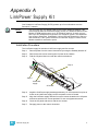
1
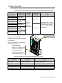
Wall Mount, CE Installation Manual Revision C C o p y r i g h t © E le c tr o n i c T h e a t r e C o n t r o l s , I n c . All Rights reserved. P r o d u c t i nf o r m a t i o n a n d s p e c i f i c a t i o n s s u b je c t t o c h a n g e . P a r t N u m b e r : 7021M2130-GB R e v C R e le a s ed : 2 0 0 9 - 0 6 Table of Contents Introduction . . . . . . . . . . . . . . . . . . . . . . . . . . . . . . 1 Using this Manual . . . . . . . . . . . . . . . . . . . . . . . . . . . . . . . . . . . . . . . .1 Product Variants. . . . . . . . . . . . . . . . . . . . . . . . . . . . . . . . . . . . . . . . .2 Help from ETC Technical Services . . . . . . . . . . . . . . . . . . . . . . . . . .3 Prepare for Installation . . . . . . . . . . . . . . . . . . . . . . 4 Installation Environment. . . . . . . . . . . . . . . . . . . . . . . . . . . . . . . .4 Electrical Requirements . . . . . . . . . . . . . . . . . . . . . . . . . . . . . . . .4 Cable Specification . . . . . . . . . . . . . . . . . . . . . . . . . . . . . . . . . . .4 Compliance . . . . . . . . . . . . . . . . . . . . . . . . . . . . . . . . . . . . . . . . .5 Verify the Contents of the Shipping Carton . . . . . . . . . . . . . . . . .5 Additional Parts and Specialty Tools Required . . . . . . . . . . . . . .5 Cable Routing and Conduit Access . . . . . . . . . . . . . . . . . . . . . . .6 Installation Procedure . . . . . . . . . . . . . . . . . . . . . . 7 Install Mounting Hardware . . . . . . . . . . . . . . . . . . . . . . . . . . . . . .7 Mount the SmartPack . . . . . . . . . . . . . . . . . . . . . . . . . . . . . . . . .7 Rough-In Conduit and Cable . . . . . . . . . . . . . . . . . . . . . . . . . . . .8 Connect Wiring . . . . . . . . . . . . . . . . . . . . . . . . . . . . . . . . . . . . . . . . . .9 Power Supply Connections . . . . . . . . . . . . . . . . . . . . . . . . . . . . .9 Three-Phase Supply Connections . . . . . . . . . . . . . . . . . . . . .9 Single-Phase Supply Connections (Europe) . . . . . . . . . . . . .9 Load Connections . . . . . . . . . . . . . . . . . . . . . . . . . . . . . . . . . . .10 Earth/Ground Connections . . . . . . . . . . . . . . . . . . . . . . . . . .10 Neutral Connections . . . . . . . . . . . . . . . . . . . . . . . . . . . . . . .10 Connect Control Wiring . . . . . . . . . . . . . . . . . . . . . . . . . . . . . . .11 Emergency/SmartLink . . . . . . . . . . . . . . . . . . . . . . . . . . . . .11 Connect Emergency . . . . . . . . . . . . . . . . . . . . . . . . . . . . . . . . . 12 Connect SmartLink . . . . . . . . . . . . . . . . . . . . . . . . . . . . . . . . . . 12 Connect ESD Ground . . . . . . . . . . . . . . . . . . . . . . . . . . . . . .13 DMX 512 . . . . . . . . . . . . . . . . . . . . . . . . . . . . . . . . . . . . . . . .13 Connect DMX . . . . . . . . . . . . . . . . . . . . . . . . . . . . . . . . . . . . . . 13 Data Termination . . . . . . . . . . . . . . . . . . . . . . . . . . . . . . . . . . . .14 Guidelines for Data Termination: . . . . . . . . . . . . . . . . . . . . .14 Final Installation and Power Up . . . . . . . . . . . . . . . . . . . . . . . . . . . .15 Verify Installation . . . . . . . . . . . . . . . . . . . . . . . . . . . . . . . . . . . .15 Final Installation . . . . . . . . . . . . . . . . . . . . . . . . . . . . . . . . . . . . .15 Test Loads via Menu . . . . . . . . . . . . . . . . . . . . . . . . . . . . . . . . .15 Select the operating language: . . . . . . . . . . . . . . . . . . . . . . .15 Set a level for a dimmer: . . . . . . . . . . . . . . . . . . . . . . . . . . . .16 Verify DMX512 Operation . . . . . . . . . . . . . . . . . . . . . . . . . . . . .16 Troubleshooting SmartLink . . . . . . . . . . . . . . . . . . . . . . . . . . . .16 LinkPower Supply Kit . . . . . . . . . . . . . . . . . . . . . . 17 Installation Procedure . . . . . . . . . . . . . . . . . . . . . . . . . . . . . . . .17 ETC ®, Smar t Pa ck™, Sma rt Swit ch ™ an d Smar t Li nk ™ ar e e it he r r e gi st er ed tr a de mar ks o r t r ad ema rk s of E le ct ro ni c Th ea t re Co nt r ol s, In c. i n t he Un it e d S ta te s an d ot h er cou nt r ie s. Lo nWo r ks ® an d LON ® ar e r e gi st er ed tr a dema r ks of t he E ch el on ® Co rp or a ti on . Al l ot h er tr a dema r ks, bo th mar ke d an d no t ma r ked , a r e t he p ro pe r ty o f t he ir r es pec ti ve o wne rs . Introduction Congratulations on your purchase of the ETC® SmartPack™ Wall Mount dimming pack. SmartPack continues ETC's tradition of providing the highest quality products for the entertainment and architectural lighting market. Using thi s Manual Use this manual during the installation of the SmartPack Wall Mount unit. This manual includes instructions for installing SmartPack units to operate together on a SmartLink™ control network. For user configuration and system operation instructions please refer to the Wall Mount SmartPack User Manual. The following symbols are used in this manual to alert you to danger or important information. Note: Provides important information about your installation. CAUTION: A Caution statement indicates situations where there may be undefined or unwanted consequences of an action, potential for data loss or an equipment problem. WARNING: A Warning statement indicates situations where damage may occur, people may be harmed, or there are serious or dangerous consequences of an action. WARNING: RISK OF ELECTRIC SHOCK! This warning statement indicates situations where there is a risk of electric shock. Please email comments about this manual to: [email protected] Introduction 1 Product Variants The instructions in this manual apply to the CE SmartPack Wall Mount dimming packs Part Number 7021A1103 7021A1103-LPS 7021A1105 7021A1105-LPS 7021A1106 7021A1106-LPS 7021A1107 7021A1107-LPS 7021A1110 7021A1110-LPS Channel Count/ Breaker Type Operating Voltage Installed Weight (loaded) Notes 12 channel / 10A breakers 12 channel / 10A (ND) 2 pole breakers 6 channel / 15A breakers 6 channel / 15A (ND) 2 pole breakers 3 channel / 25A (ND) 2 pole breakers 22Kg / 48lbs 230 VAC 47-63Hz single or three phase 21Kg / 46lbs 3, 6, or 12 dimmer channels available A SmartPack with a “-LPS” part number suffix includes a LinkPower supply which is factory installed for SmartLink station power. Cover removed for clarity Variable speed cooling fan Capable of dimming multiple load types CE Compliant 32 built-in presets and a sequencer for stand-alone operation. I/O compartment DMX512 In / DMX512 Thru Emergency contact input SmartLink™ enabled Optional LinkPower supply for wall station support. Option kits available for the SmartPack Wall Mount unit include: Part Number 2 Description 7021K1010 LinkPower supply kit 7021K1000 7021K1004 7021K1008 7021K1006 19” Rack mount kit RCD kit RCD/40A Mains Breaker kit RCD/63A Mains Breaker kit Notes optional - supplies power for up to four SmartLink wall stations requires 15 rack units of space SmartPack Wall Mount Installation Manual Help from ETC Technical Services If you are having difficulties, your most convenient resources are the references given in this manual. To search more widely, try the ETC web site at www.etcconnect.com. If none of these resources is sufficient, contact ETC Technical Services directly at one of the offices identified below. Emergency service is available from all ETC offices outside of normal business hours. When calling for help, please have the following information handy: • Model of SmartPack Wall Mount • Other components in the system (if any) including other Smartlink host products, LinkPower supply, quantity and type of SmartLink wall stations, etc. • DMX control source used for system-wide control. Americas United Kingdom ETC International Electronic Theatre Controls, Ltd. Technical Services Department Technical Services Department 3031 Pleasant View Road Unit 26-28 Victoria Industrial Estate Middleton, WI 53562 Victoria Road, 800-775-4382 (USA, toll-free) London W3 6UU, UK +1-608 831-4116 +44 (0)20 8896 1000 [email protected] [email protected] Asia Germany ETC Asia, Ltd. Electronic Theatre Controls, GmbH Technical Services Department Technical Services Department Room 1801, 18/F, Ohmstrasse 3 Tower I, Phase I, Enterprise Square 93607, Holzkirchen, Germany 9 Sheung Yuet Road +49 (80 24) 47 00-0 Kowloon Bay, Kowloon, Hong Kong [email protected] +852 2799 1220 [email protected] Introduction 3 Prepare for Installation Installation Environment • Dry room (30-95% humidity, non-condensing) • 0-35°C (32-95°F) ambient temperature • Dust free • Wall-mounting location must support 23kg (50lbs) • Minimum 25.4cm (10”) clearance in front of unit for airflow vents Electrical Requirements • 50-60Hz • 230/400 VAC, 3Ø+N+PE 40A per phase • 230 VAC, 1Ø+N+PE 120A per phase • For use on TN-C, TN-S, TN-CS and TT supplies • Not suitable for use on Delta IT supplies • This equipment must be connected to a suitable safety earth/ground. Cable Specification Purpose Cable Type/Description Note AC Input - Three phase 230/400 VAC 3Ø+N+PE, 50-60Hz, 40A per phase AC Input - Single phase 230 VAC, 1Ø+N+PE, 50-60Hz, 120A per phase 25mm2 / 2AWG maximum stranded cable Use only cables of size and rating complying with local wiring regulations. Supply gauge must be coordinated with upstream protective switchgear. DMX512 Recommended - Belden 9729 Alternatives Carol - C0910 General -0E8990 Olfex - 9729 Omni - D62402 Quabbin - 8604 Olympic - 2998 Pro-Plex - PC224T SmartLink™ Belden 8471 plus 1 - 2.50mm2 ESD drain wire recommended (drain wire not required if installed in grounded metal conduit). Emergency 2 - 1.5mm2 twisted 4 CAT 5 cable is also approved for DMX distribution if installed in grounded metal conduit. • For use of CAT 5 cable, you will need to purchase a CAT 5 termination kit (ETC part number 4100A1013) from a local ETC office or service provider. For use with wall stations and SmartLink pack to pack synchronization. SmartLink is FTT10A topology-free and polarity independent. Contact input for emergency lighting loads. SmartPack Wall Mount Installation Manual Compliance CE Compliance • EN55015, EN55022B, EN61000-6-2, EN60439-1 • Complies with CE Directives 336/83/EEC and 73/23/EEC Verify the Contents of the Shipping Carton • SmartPack unit with cover attached. • Warning labels. If necessary replace the warning label on your SmartPack unit with the label displaying the operational language of the installed location. • SmartPack User Manual and Mounting Template. • DMX Cable Preparation Kit with 8-pin connector (4100A1012). A d d i t i o n a l P a r t s a n d S pe c i a l t y T o o l s R e q u i r e d • 4 x 6-8mm (1/4” - 3/8”) bolts or screws, 50-100mm (2 - 4”) long, and suitable wall plugs, are suggested. Mounting hardware and surface must support 23kg (50 lbs). • Conduit punch, Conduit or bushes 12.7mm (1/2”) diameter • Slotted screwdriver for line terminals • Phillips screwdriver • 4.75mm (3/16”) wide slotted-style screwdriver for load terminals • Jeweler’s screwdriver for data terminals • Wire strippers Prepare for Installation 5 Cable Routing and Conduit Access CAUTION: In order to maintain safety, proper air flow and cooling, do not leave any panels removed unless facing an adjoined pack. Removable plates on either side. Remove appropriate plate to punch conduit access as needed for AC Input and load wiring. Remove plate permanently if SmartPack is mounted to the side of another SmartPack. Removable plates on top and bottom. Remove appropriate plate to punch conduit access as needed for AC Input and load wiring. Remove plate permanently if SmartPack is mounted below another SmartPack or SmartSwitch. Rear Load Terminals AC Input Lugs Earth/Ground Bus Rear 6 11 L 12 L 9L 10 L 8L 7N 7 L2 8N 8 L2 9N 9 L3 10 N 10 L3 11 N 11 L3 12 N 12 L3 7L 6L 5L 4L 3L 1L Left Side 2L Bottom Rear Knockouts in the lower side panels accommodate conduit or bushes for low voltage control wiring to the I/O compartment. Right Side Rear 1N 1 L1 2N 2 L1 3N 3 L1 4N 4 L1 5N 5 L2 6N 6 L2 Top Access Holes for mounting bolts or screws. I/O Compartment - all lowvoltage (control terminations conveniently located in the lower panel. SmartPack Wall Mount Installation Manual Installation Procedure Install Mounting Hardware Step 1: Affix the mounting template, if included in the shipping carton, to the wall to guide the placement of the mounting bolts or screws. If the mounting template is not provided, use the measurements below. 127mm (5.0”) 305mm (12.0”) Step 2: Note: • SmartPack Wall Mount units may be mounted up to two high by any width. Allow clearances as described on page 4 • Overall dimensions of the enclosure: 435mm x 157mm x 666mm 17.15” x 6.2” x 26.24” Install the hardware required for mounting the SmartPack using the four measured keyholes on the mounting template as a guide. • Four 6-8mm (1/4” - 3/8”) bolts or screws, 50-100mm (2 - 4”) long, and suitable wall plugs are suggested mounting hardware. • Both the surface and the mounting hardware must support 23kg (50lbs). • Expose at least 25mm (1”) of threads for mounting the SmartPack. Access holes to tighten bolts / screws are shown in the Cable Routing and Conduit Access graphic on page 6. Mount the SmartPack Step 1: Remove the four screws securing the cover to the SmartPack. Step 2: Remove the cover assembly. Note: The SmartPack Wall Mount unit ships with a debris shield to protect the electronics during installation. Leave this shield in place during installation and remove only after installation is complete and before energization. Step 3: Mount the SmartPack to the mounting bolts previously installed. Step 4: Tighten the bolts securely. • Installation Procedure Check for a plumb installation and follow all local code restrictions. 7 Rough-In Conduit and Cable SmartPack Wall Mount dimmer packs have removable plates located on top, bottom and both sides to accommodate conduit fittings for supply and load wiring. Additional wiring space is provided at the top of the unit for contractor wiring convenience. Two knockouts are provided, one on each lower side, specifically for low voltage (control) wiring. See “Cable Routing and Conduit Access” on page 6. Step 1: Install conduit for AC input power and load wiring to the panels in the appropriate locations. • Step 2: Note: The SmartPack dimmer pack is available with either 3, 6, or 12 dimmers. Make certain conduit is sized appropriately for the required wire. Install conduit as required for low voltage (control) wiring. Low voltage wiring must be routed separately from high voltage wiring. a: All low voltage terminations are conveniently located in the I/O compartment of the SmartPack. Two 12.7mm (1/2”) knockouts are provided for low voltage control wiring. Step 3: Pull AC input wiring and load wiring through the conduit previously installed. a: Individual loads with earth ground and neutral connections. b: Power supply wiring for predetermined three-phase or single phase operation. CAUTION: Step 4: 8 The SmartPack Wall Mount unit ships with a debris shield to protect the electronics during installation. Leave this shield in place during installation and remove only after installation is complete, before energization. If debris falls into the fan or electronics remove the debris before applying power to the unit. Pull all low voltage control wiring through the conduit previously installed to the I/O compartment knockouts. Installation requirements for low voltage wiring may include the following: • DMX IN - required when SmartPack is to be controlled by a DMX source. • DMX PASS-THRU - allows pass-thru of the DMX signal to other DMX devices. • SmartLink - station wiring is FTT-10A, topology-free and polarity independent. Wiring may be bus, star, loop, home run (up to two home run termination points available) or any combination of these. • Emergency - receives a contact input that switches selected emergency lighting loads to full and all non-emergency lighting loads OFF. Contact ETC for guidance on use with emergency lighting systems. SmartPack Wall Mount Installation Manual Connect Wiring Power Supply Connections Three-Phase Supply Connections Note: If a DIN rail option kit is fitted with RCD and/or terminals, please follow the wiring instructions supplied with the kit. Input Wiring L1 N2 L2 N N2 L3 L1 N1 EARTH L2 LOAD1 Important Note: Supply cable gauge must be coordinated with upstream protective switchgear. L3 N1 Earth LOAD1 Supply cable: Lugs will accommodate 25mm2 / 3AWG maximum stranded cable. N To Circuit Breakers Single-Phase Supply Connections (Europe) Important Note: Jumper wires must match specifications for incoming line wire. Important Note: For operation on single phase supplies at full power, upstream switchgear, such as RCD's or main breakers, must be located separately outside the enclosure. Please contact ETC technical services for assistance. Input Wiring Earth L1 L3 EARTH L3 N L2 L2 L1 N To Circuit Breakers CAUTION: The SmartPack Wall Mount unit ships with a debris shield to protect the electronics during installation. Leave this shield in place during installation and remove only after installation is complete and before energization. If debris falls into the fan or electronics remove the debris before applying power to the unit. Installation Procedure 9 Load Connections Earth/Ground Connections Connect the earth/ground conductor for each load to the Earth/Ground Bus. N N 12 N 12 L3 N 11 L3 10 L3 11 N N 10 N 9 L3 9N N 8 L2 8N 7 N2 N 7N 6 L2 N 6N 5 L2 N 5N 4 L1 4N 3 L1 N 3N 2 L1 N 2N 1 L1 N N 1N Incoming Load Wiring Earth/Ground Bus Neutral Connections Step 1: Prepare load conductors by stripping 6mm of insulation from the end. Step 2: Insert the stripped end into the terminal and tighten the screw using a 4.75mm (3/16”) wide slotted style screwdriver. • Terminals accept wire between 1.5mm2 / 16AWG and 6mm2 / 8AWG. • Take care not to tighten the load connection onto the wire insulation. 9 L3 9N 8 L2 8N 7 N2 7N 6 L2 6N 5 L2 5N 4 L1 4N 3 L1 3N 2 L1 2N 1 L1 1N Insert load conductors here. 10 N N These wires installed by ETC prior to shipping the unit. SmartPack Wall Mount Installation Manual Connect Control Wiring I/O panel to chassis ground Link Power supply (optional) Data to CPU Emergency /SmartLink DMX In DMX Thru ESD Ground Emergency, SmartLink, DMX In and DMX Pass-Thru are connected in the I/O compartment of the SmartPack Wall Mount unit. Each connection uses a pluggable screw terminal which can be removed for easy wiring. The RJ45 connection labeled J2 on the I/O board connects the I/O control board to the control CPU board for data communication to the SmartPack. This connection is made at the factory prior to shipment. The LinkPower supply provides power for up to four SmartLink wall stations per system. SmartPack Wall Mount is available with or without the LinkPower supply option. For field installation of the LinkPower supply reference LinkPower Supply Kit, page 17. Emergency/SmartLink SmartLink is a control protocol that provides added functionality to the SmartPack dimming pack for inter-connectivity and shared communication of specific data to other SmartLink enabled host products. Reference the SmartPack User Manual for configuration details. Unison DRd12 SmartPack SmartPack rack SmartPack LinkPower supply installed Presets, Sequence, Sequence Timing SmartLink ATC Belden 8471 plus 12.5mm2 ESD drain Recall Preset Up Back Enter Down Preset 1 Preset 2 SmartLink Preset 3 Preset 1 Preset 4 Preset 2 Stations Hold Preset 6 Preset 7 Preset 5 Preset 3 Preset 8 Preset 1 Preset 4 Preset 9 Preset 5 Preset 10 Preset 2 Preset 3 Preset 4 Preset 5 Installation Procedure 11 Emergency COM NET A NET B NET A NET B The six position pluggable screw terminal labeled J3 Panic/LON is provided as the termination point for both Emergency and SmartLink control. DMX NC LON2 J2 Control LON1 1 2 3 4 5 6 PAN COM NETA NETA NETB NETB 1 2 3 4 Connect Emergency Step 1: Strip 6.35mm (1/4”) of insulation from the ends of the two 1.5mm2 wires. Step 2: Remove the 6 position pluggable connector from J3 on the I/O PCB. Step 3: Twist the two 1.5mm2 wires together as close to the connector as possible. Step 4: Insert the 1.5mm2 into pins 5 and 6. Step 5: Tighten the screw firmly onto each wire. Connect SmartLink Termination is available for up to two separate SmartLink data runs and is FTT-10A topology-free and polarity independent utilizing a LonWorks® network. For systems utilizing SmartLink wall stations, ETC recommends terminating the station data run to the SmartPack with the LinkPower supply installed and utilizing the second data bus for SmartLink pack to pack synchronization. A clean, well organized wire installation assists with troubleshooting efforts when needed. Note: 12 One SmartLink host product (SmartPack, SmartSwitch, Unison DRd with SmartLink or Sensor + with SmartLink) in the system must have a LinkPower Supply or Station Power Module installed for wall station power. A SmartLink LinkPower supply (7021K1010) is limited to powering four SmartLink stations. Alternatively, you may power up to 16 SmartLink stations when using a SmartLink Station Power Module (S-SPM). You may have up to four SmartLink host products in a SmartLink system. Step 1: Cut the Belden 8471 cable so that a 20cm (8”) tail extends from the edge of the panel. Step 2: Strip 18cm (7”) of the outer jacket off. Step 3: If pulling two Belden 8471 cables, label each pair with data type and run designation. Example: SL1 and SL2. Step 4: Strip 6.35mm (1/4”) of insulation from the ends of the Belden 8471 wires. Step 5: Insert the white wire from SL1 data run into pin 1 (NETB) terminal on the pluggable connector. Tighten the screw firmly onto the wire. Step 6: Insert the associated SL1 black wire into pin 2 (NETA) terminal on the pluggable connector. Tighten the screw firmly onto the wire. Step 7: Repeat steps 5-6 to terminate the second data run (SL2) if required to the remaining pins 3 and 4 terminals on the connector. Tighten the screw firmly onto each wire. Step 8: Reinstall the 6 position pluggable connector to J3 on the I/O PCB. SmartPack Wall Mount Installation Manual Connect ESD Ground For installations with SmartLink data runs (Belden 8471) installed in grounded metal conduit there is no need to run or terminate an additional ESD drain wire. For installations not installed in grounded metal conduit follow the instructions below for ESD termination. Step 1: Locate the grounding lug on the tray of the I/O panel, just to the right of the I/O termination board. Step 2: Loosen, but do not remove, the set screw on the grounding lug. Step 3: Strip 6.35mm (1/4”) of insulation from the end of the 2.5mm2 ESD drain wire(s) and twist together. Step 4: Insert the bare end into the grounding lug and secure with the set screw. DMX 512 Two 8 position receptacles are provided on the I/O termination board, one for DMX In and the other for DMX-Thru. Prior to connecting DMX, follow the instructions for Belden 9729 cable preparation as defined on the single sheet instructions packaged with the 8 position pluggable screw connector. A cable preparation kit for installation of CAT 5 cable (ETC part number 4100A1013) is available for purchase, contact ETC for details. Connect DMX (J5) DMX PASS-THRU (J4) DMX IN As shown with Belden 9729 color code Pin 1 - Com n/c n/c n/c n/c n/c n/c n/c n/c n/c n/c Pin 2 - DMX - (Black) 1 2 3 4 5 6 7 8 1 2 3 4 5 6 7 8 Pin 3 - DMX + (Red) DMX In and Pass-Thru on the same pluggable screw connector as shown. 8 7 6 DATA- DATA+ DMX- DMX+ ISOCOM 8 7 6 DMX+ DATA- DATA+ COM DMX- For use with CAT 5 cable, contact ETC for a CAT 5 termination and IDC connector kit (ETC part number 4100A1013), sold separately. 7021B5602 preliminary Step 1: For DMX In and DMX Pass-Thru using Belden 9729 as recommended, prepare the Belden cable as described in the DMX Cable Preparation kit instructions. Step 2: Using the 8 position pluggable screw connector provided in the cable preparation kit, connect Shield (Com), DMX- and DMX+ as indicated in the graphic above. Step 3: DMX Pass-Thru using Belden 9729 can utilize the same pluggable screw connector as DMX In. Connect Shield (Com), DMX - and DMX + as indicated in the graphic above. Installation Procedure 13 Data Termination DMX Switch UP= termination ON NC LON J2 Control LON The I/O board includes termination switches for both SmartLink data runs and DMX512. Follow termination guidelines as indicated in the graphic below. Switch DOWN = termination OFF NETB NETA 1 2 3 4 Guidelines for Data Termination: For SmartLink (silk-screened as LON) data termination: • For a single pack installation set switch 1 and 2 to the UP position. • If multiple packs are installed, only one pack should terminate LON, switch 1 and 2 UP. All other packs should have LON switches 1 and 2 set DOWN. • If there are no SmartLink data runs set switch 1 and 2 DOWN. For DMX 512 data termination: 14 • If the pack is the last or the only DMX device on the data run set switch 3 UP. • If the pack is not the last DMX device on the data run set switch 3 DOWN. SmartPack Wall Mount Installation Manual Final Installation and Power Up Verify Installation • Is the SmartPack unit securely mounted with all mounting bolts tight? • Is there sufficient clearance 254mm (10”) in front of the unit? • Check wiring: • • Are all power supply and load cables landed and properly terminated? • Are all emergency lighting circuits separated from normal circuits with a voltage barrier? • Are all unused cable access openings covered with plugs or removable plates? • Do all control cables meet specifications? • Are all low voltage connections terminated properly? • Are all data terminations terminated? Remove all debris and the debris shield from the unit. • The SmartPack Wall Mount unit ships with a debris shield to protect the electronics during installation. Leave this shield in place during installation and remove only after installation is complete and before energization. If debris falls into the fan or electronics remove the debris before applying power to the unit. Final Installation Step 1: Attach the ground wire with the ring terminal from the chassis to the grounding stud on the I/O panel and secure. Step 2: Close the I/O panel and secure with two screws. a: All wires should be dressed neatly. b: Ensure the wires are not crimped in the I/O Panel while closing. Step 3: Attach the ground wire with the spade connector to the front cover and secure the front cover to the unit. Step 4: Apply power to the unit. Test Loads via Menu After power is applied to the unit, select the operating language and test each load using the TEST MENU. Select the operating language: Step 1: Apply power to the unit. Available languages for SmartPack will scroll in the display at 3-second intervals. Step 2: Press when the preferred language is displayed: •Set Language - English •Choisir la langue - Français •Sprache auswählen - Deutsch •Seleccionar idioma - Español Installation Procedure 15 Set a level for a dimmer: Step 1: Press Step 2: Use < or to enter the Test menu. to scroll the selection of dimmers, choose one or [ALL] dimmers. Test Dimmer: [ All ] T Level: 100% Step 3: Use + or - to set a level, press Step 4: Press . The menu will progress to the next dimmer. . “Exit Test Mode” displays. • Exit Test Mode and retain all Test levels, scroll to [Keep Test On] and press . • Exit Test menu, clearing all Test levels and return to the previous menu, scroll to [Test: all off], press . • Press < to return to the Test menu. • Press << to exit the Test menu, clearing all Test levels, and return to the main menu. Verify DMX512 Operation Test each load with DMX512 input using a controle console or DMX512 test device. Troubleshooting SmartLink After all SmartLink control stations are installed and connected to the SmartLink enabled product, check for shorts and cross-connections with a digital voltmeter. • Check the voltage between Net A and ground. This reading should be between 18 - 21 Volts. • Check the voltage between Net B and ground. This reading also should be between 18-21 Volts. • Check the voltage between Net A and Net B. This reading should be between 3642 Volts. Check that two LED indicators (located at CR1 and CR2) are illuminated on the LinkPower supply board. • If both are illuminated the data connections are good. • If CR1 is illuminated but not CR2, Net A is shorted to ground. • If CR2 is illuminated but not CR1, Net B is shorted to ground. • If neither LED is illuminated, Net A and Net B are both shorted. If you have any difficulties installing your system, please contact ETC Technical Services at the office nearest you. 16 SmartPack Wall Mount Installation Manual Appendix A LinkPower Supply Kit One SmartLink LinkPower Supply (S-LPS) powers up to four wall stations over the SmartLink™ network. Note: You may have only one station power source on the SmartLink network. This source may be either the LinkPower Supply (S-LPS) or a SmartLink Station Power Module (S-SPM) which powers up to 16 SmartLink stations. As well, you may have up to four SmartLink host products in a SmartLink system. One SmartLink host product (SmartPack, SmartSwitch, Unison DRd with SmartLink or Sensor + with SmartLink) in the system must have a LinkPower Supply or Station Power Module installed for wall station power. Installation Procedure The LinkPower supply kit includes a LinkPower supply and four screws. Step 1: Remove power from the control electronics by turning the Standby breaker off. Step 2: Remove the two screws securing the I/O panel to the chassis. Step 3: Fold the I/O panel down to reveal the control terminations. Step 4 Step 5 LinkPower supply I/O board A Step 4: Angle the LinkPower supply board approximately 10° and insert the four pins as found on the LinkPower supply into the receptacle on the I/O board. Step 5: Align the LinkPower supply with the four screw mounts located on the I/O panel and secure with the four screws provided. Do not over tighten the screws. Step 6: Close the I/O panel and secure with the two screws. Step 7: Re-apply power to the control electronics. LinkPower Supply Kit 17 Corporate Headquarters 3031 Pleasant View Road, P.O. Box 620979, Middleton, Wisconsin 53562-0979 USA Tel +608 831 4116 Fax +608 836 1736 London, UK Unit 26-28, Victoria Industrial Estate, Victoria Road, London W3 6UU, UK Tel +44 (0)20 8896 1000 Fax +44 (0)20 8896 2000 Rome, IT Via Ennio Quirino Visconti, 11, 00193 Rome, Italy Tel +39 (06) 32 111 683 Fax +44 (0) 20 8752 8486 Holzkirchen, DE Ohmstrasse 3, 83607 Holzkirchen, Germany Tel +49 (80 24) 47 00-0 Fax +49 (80 24) 47 00-3 00 Hong Kong Rm 1801, 18/F, Tower 1 Phase 1, Enterprise Square, 9 Sheung Yuet Road, Kowloon Bay, Kowloon, Hong Kong Tel +852 2799 1220 Fax +852 2799 9325 Service: (Americas) [email protected] (UK) [email protected] (DE) [email protected] (Asia) [email protected] Web: www.etcconnect.com Copyright © 2009 ETC. All Rights Reserved. Product information and specifications subject to change. 7021M2130-GB Rev C Released 2009-06