1
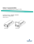
NetSure™ Control Unit (NCU)
User Manual, UM1M830BNA
(Revision F, July 20, 2015)
Specification Number: 1M830BNA, 1M830DNA
Model Number: M830B, M830D
Software Version 1.1.40
Model M830B
Model M830D
NetSure™ Control Unit (NCU)
User Manual, UM1M830BNA
This page is intentionally blank.
Spec. No: 1M830BNA, 1M830DNA
Model No: M830B, M830D
Code: UM1M830BNA
Revision F, July 20, 2015
NetSure™ Control Unit (NCU)
User Manual, UM1M830BNA
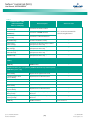
Table of Contents
Admonishments Used in this Document .............................................................................................................. vii
Introduction ......................................................................................................................................................... 1
Preface ................................................................................................................................................................... 1
Overview ................................................................................................................................................................ 1
Function Descriptions ............................................................................................................................................. 2
Rectifier, Solar Converter, and Converter Control ............................................................................................. 2
System Components Monitoring and System Alarms Generation ..................................................................... 2
Operating Data Acquisition and Data Logs ....................................................................................................... 2
Battery Management ....................................................................................................................................... 2
Battery Charge Temperature Compensation ............................................................................................. 3
Battery Equalize Charge and Battery Charge Current Limit ......................................................................... 3
High and Low Battery Temperature Alarms ............................................................................................... 4
Battery Thermal Runaway Management (BTRM) Feature ........................................................................... 4
Battery Discharge Test and Battery Test Logs ............................................................................................ 4
Battery LVD (Low Voltage Disconnect) ...................................................................................................... 5
Battery Capacity Prediction ....................................................................................................................... 5
Battery Block and Battery Midpoint Monitoring ......................................................................................... 5
Enhanced Battery Monitoring with SM-BRC ............................................................................................... 5
Thermal Runaway Detection and Management ......................................................................................... 5
Energy Management ....................................................................................................................................... 6
Energy Optimization Mode ....................................................................................................................... 6
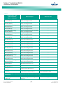
Power Split Feature .......................................................................................................................................... 6
Diesel Management Feature ............................................................................................................................ 8
Supervisory Module (SM Modules) Monitoring ................................................................................................. 8
Hybrid Control Function (Supporting Generator, Solar and Wind Energy Input, and Optimization) .................... 8
General .................................................................................................................................................... 8
Hybrid Operation ..................................................................................................................................... 8
Early Termination of the Discharge Periods ............................................................................................... 9
Operation with Grid Power ....................................................................................................................... 9
Relay Assignment – when in Hybrid Mode ............................................................................................... 10
Fixed Daily .............................................................................................................................................. 10
Capacity Discharge ................................................................................................................................. 10
Maximum Current Limit Function ................................................................................................................... 10
Communications Function ............................................................................................................................. 11
FIAMM SoNick (Sodium Nickel) battery Interface ............................................................................................ 11
Operation ........................................................................................................................................................... 12
Local Indicators..................................................................................................................................................... 12
Passwords and Privilege Levels .............................................................................................................................. 13
Multiple Languages Supported.............................................................................................................................. 13
Using the Local Keypad and Display ....................................................................................................................... 14
Spec. No: 1M830BNA, 1M830DNA
Model No: M830B, M830D
[i]
Code: UM1M830BNA
Revision F, July 20, 2015
NetSure™ Control Unit (NCU)
User Manual, UM1M830BNA
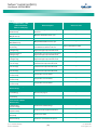
Local Menu Navigation Keys and Local Display ................................................................................................ 14
Local Display Menus ....................................................................................................................................... 14
Navigating the Menus ............................................................................................................................. 14
Using the Web Interface ........................................................................................................................................ 15
Overview ....................................................................................................................................................... 15
Multiple Browsers Supported ......................................................................................................................... 15
Web Interface Screens ................................................................................................................................... 15
Procedures .................................................................................................................................................... 15
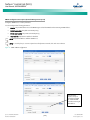
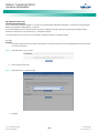
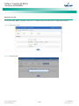
Setting IPv4 Communications Parameters (if controller not set as DHCP) ................................................. 15
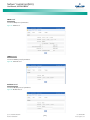
Setting IPv6 Communications Parameters (if controller not set as DHCPv6) ............................................. 15
Setting for DHCP and DHCPv6 ................................................................................................................. 15
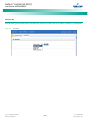
Connecting the Controller to your Local Area Network (LAN) ................................................................... 15
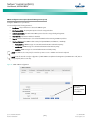
Connecting a Local Computer Directly to the Controller .......................................................................... 16
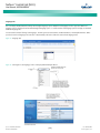
Disabling Proxy Server Settings to Enable a Connection to the Controller over an Intranet
Network (if required) .............................................................................................................................. 17
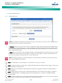
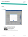
Internet Security Settings for Loading Files or Downloading Files into the NCU ......................................... 17
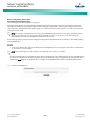
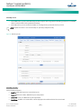
Logging into the Controller ..................................................................................................................... 19
Common Tasks Performed via the Local Keypad and/or Web Interface ................................................................... 20
Procedures .................................................................................................................................................... 20
Start Wizard............................................................................................................................................ 20
Viewing Alarms ....................................................................................................................................... 20
Viewing System Status ............................................................................................................................ 20
Viewing the NCU Controller’s Device Inventory ....................................................................................... 20
Clearing or Resetting Alarms ................................................................................................................... 20
Clearing Logs .......................................................................................................................................... 20
Disabling the Local Keypad Sound ........................................................................................................... 20
Blocking Alarms ...................................................................................................................................... 20
Changing the Date and Time ................................................................................................................... 20
Adding, Deleting, and Modifying Users .................................................................................................... 21
Setting IP Communications Parameters (if controller not set as DHCP or DHCPv6) ................................... 21
Setting for DHCP and DHCPv6 ................................................................................................................. 21
Setting SNMP Parameters ....................................................................................................................... 21
Setting Auto Equalize .............................................................................................................................. 21
Programming the Audible Alarm Feature................................................................................................. 22
Manually Forcing LVDs ............................................................................................................................ 22
Manually Forcing Relays .......................................................................................................................... 22
Assigning Severity Level to Alarms ........................................................................................................... 22
Assigning Relays to Alarms ...................................................................................................................... 22
Placing the System in Float or Equalize Charge Mode ............................................................................... 22
Viewing/Changing the Float Voltage Setting ........................................................................................... 23
Viewing/Changing the Equalize Voltage Setting ...................................................................................... 23
Setting Battery Parameters ..................................................................................................................... 23
Spec. No: 1M830BNA, 1M830DNA
Model No: M830B, M830D
[ii]
Code: UM1M830BNA
Revision F, July 20, 2015
NetSure™ Control Unit (NCU)
User Manual, UM1M830BNA
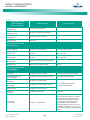
Setting Battery Capacity Parameters ....................................................................................................... 23
Setting Rectifier High Voltage Shutdown ................................................................................................ 23
Setting Solar Converter High Voltage Shutdown ..................................................................................... 23
Setting Rectifier Current Limit................................................................................................................. 23
Checking the Controller’s Current Limit Point after Adding or Removing a Rectifier, Solar
Converter, or Converter Module ............................................................................................................. 23
Enabling Solar Mode ............................................................................................................................... 24
Setting Over Voltage Alarm 1.................................................................................................................. 24
Setting Over Voltage Alarm 2.................................................................................................................. 24
Setting Under Voltage Alarm 1 ............................................................................................................... 24
Setting Under Voltage Alarm 2 ............................................................................................................... 24
Setting Temperature Sensors.................................................................................................................. 24
Setting Battery Charge Temperature Compensation ............................................................................... 25
Setting Battery Thermal Runaway Management (BTRM) Feature ............................................................. 25
Configuring the NCU Identification of Rectifiers and Assigning which Input Feed is Connected
to the Rectifiers ...................................................................................................................................... 25
Configuring the NCU Identification of Solar Converters ........................................................................... 26
Configuring the NCU Identification of Converters .................................................................................... 26
Setting Digital Inputs .............................................................................................................................. 26
Setting Battery Block and Battery Midpoint Monitoring (if equipped with an EIB Assembly) ...................... 26
Setting External Shunts (connected to the EIB Assembly) ........................................................................ 26
Setting External Shunts (connected to the SM-DU+ Assembly) ................................................................ 27
Setting the System Current Alarm ........................................................................................................... 27
Using the Relay Test Feature ................................................................................................................... 27
Clearing the Maintenance Alarm ............................................................................................................. 27
Performing a Manual Battery Discharge Test ........................................................................................... 28
Updating the NCU Controller’s Device Inventory ..................................................................................... 28
Backing Up the NCU Configuration ......................................................................................................... 28
Reloading a Backed-Up NCU Configuration ............................................................................................. 29
Upgrading the NCU Using an Application ("All") Package .......................................................................... 29
Restoring Factory Default Configuration ................................................................................................. 29
Rebooting the Controller ........................................................................................................................ 30
Power Split Feature ............................................................................................................................................... 30
Overview ....................................................................................................................................................... 30
How Power Split Works........................................................................................................................... 30
Operating Modes ................................................................................................................................... 31
Requirements and Conditions................................................................................................................. 31
Paralleling the Existing and NCU Power Systems ...................................................................................... 31
Programming the NCU Power Split Feature ............................................................................................. 33
Verifying the Operation of the Power Split Feature .................................................................................. 34
FIAMM SoNick (Sodium Nickel) Batteries Interface................................................................................................. 35
FIAMM Battery Installation and User Instructions ............................................................................................ 35
Spec. No: 1M830BNA, 1M830DNA
Model No: M830B, M830D
[iii]
Code: UM1M830BNA
Revision F, July 20, 2015
NetSure™ Control Unit (NCU)
User Manual, UM1M830BNA
Required FIAMM Documentation ............................................................................................................ 35
FIAMM Battery SMCMonitor200 Software ............................................................................................... 35
Installation Requirements for NCU Monitoring of FIAMM Battery(s).......................................................... 35
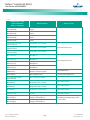
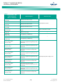
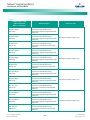
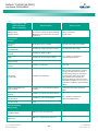
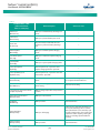
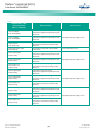
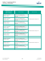
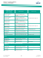
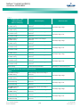
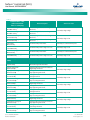
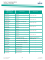
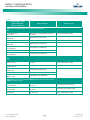
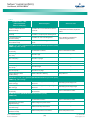
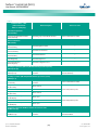
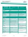
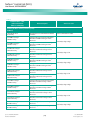
Resolving Alarms................................................................................................................................................... 37
Local Display Menus ............................................................................................................................................ 72
Overview .............................................................................................................................................................. 72
Menus................................................................................................................................................................... 72
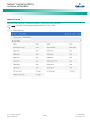
Factory Default Setpoints ............................................................................................................................... 72
Adjustment Range Restrictions ...................................................................................................................... 72
Main Menu ............................................................................................................................................................ 74
Controller Information Menu (accessed from the Main Menu) ................................................................................ 75
Alarm Menu .......................................................................................................................................................... 76
Settings Menu ....................................................................................................................................................... 77
Start Wizard Sub-Menu (accessed from Settings Menu) ......................................................................................... 82
Input Power Menu ................................................................................................................................................. 83
Module Menu ........................................................................................................................................................ 84
DC Menu ............................................................................................................................................................... 85
Battery Menu ........................................................................................................................................................ 86
Description of Local Display Menus Programmable Parameters ........................................................................... 88
Settings Menu ....................................................................................................................................................... 88
Maintenance Sub-Menu ................................................................................................................................. 88
Energy Saving Sub-Menu ................................................................................................................................ 88
Alarm Settings Sub-Menu ............................................................................................................................... 88
Rect Settings Sub-Menu ................................................................................................................................. 89
Batt Settings Sub-Menu.................................................................................................................................. 89
Basic Settings Sub-Menu ......................................................................................................................... 89
Charge Sub-Menu ................................................................................................................................... 89
Battery Test Sub-Menu ............................................................................................................................ 90
Temp Comp Sub-Menu ........................................................................................................................... 90
Batt1 Settings Sub-Menu ........................................................................................................................ 90
Batt2 Settings Sub-Menu ........................................................................................................................ 90
LVD Settings Sub-Menu .................................................................................................................................. 90
AC Settings Sub-Menu.................................................................................................................................... 91
Sys Settings Sub-Menu ................................................................................................................................... 91
Comm Settings Sub-Menu ............................................................................................................................. 91
Other Settings Sub-Menu ............................................................................................................................... 92
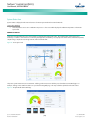
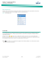
Web Interface Screens ......................................................................................................................................... 95
Overview of Web Function .................................................................................................................................... 95
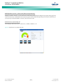
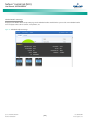
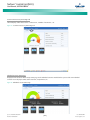
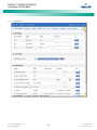
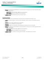
Homepage ............................................................................................................................................................ 95
System Status Information Area ............................................................................................................................ 97
System Specifications Information Area ................................................................................................................. 97
Spec. No: 1M830BNA, 1M830DNA
Model No: M830B, M830D
[iv]
Code: UM1M830BNA
Revision F, July 20, 2015
NetSure™ Control Unit (NCU)
User Manual, UM1M830BNA
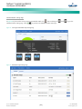
Controller Specifications Information Area ............................................................................................................ 97
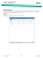
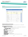
Alarms Area .......................................................................................................................................................... 98
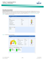
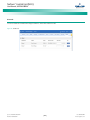
System Status Area ............................................................................................................................................... 99
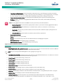
Power System Tab ......................................................................................................................................... 99
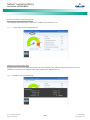
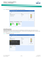
Device Group Status Pages ................................................................................................................... 100
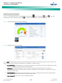
General Status Tab ...................................................................................................................................... 115
Menu Navigation Area ........................................................................................................................................ 116
Settings Menu ............................................................................................................................................. 116
Changing Programmable Parameters in the Settings Menu ................................................................... 118
Quick Settings Tab Programmable Parameter Descriptions ................................................................... 118
Equipment Tab Programmable Parameter Descriptions ........................................................................ 119
System Tab Programmable Parameter Descriptions .............................................................................. 125
Battery Tab Programmable Parameter Descriptions .............................................................................. 128
ECO Tab Programmable Parameter Descriptions ................................................................................... 130
LVD Tab Programmable Parameter Descriptions ................................................................................... 131
Temp Probes Tab Programmable Parameter Descriptions ..................................................................... 132
Rectifiers Tab Programmable Parameter Descriptions ........................................................................... 133
DC/DC Converters Tab Programmable Parameter Descriptions ............................................................. 134
Solar Tab Programmable Parameter Descriptions.................................................................................. 135
Battery Test Tab Programmable Parameter Descriptions ....................................................................... 136
Time Settings Tab Programmable Parameter Descriptions .................................................................... 136
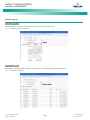
History Log Menu ........................................................................................................................................ 138
Alarm History Log Tab .......................................................................................................................... 138
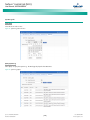
Battery Test Log Tab ............................................................................................................................. 140
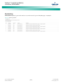
Event Log Tab ....................................................................................................................................... 142
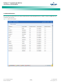
Data History Log Tab ............................................................................................................................ 144
System Log Tab .................................................................................................................................... 146
System Inventory Menu ............................................................................................................................... 148
Advanced Settings Menu ............................................................................................................................. 150
Ethernet Tab ........................................................................................................................................ 150
Users Tab ............................................................................................................................................. 151
SNMP Tab............................................................................................................................................. 153
Language Tab ....................................................................................................................................... 156
SW Maintenance Tab ............................................................................................................................ 157
Alarms Tab ........................................................................................................................................... 162
DI Alarms Tabs ..................................................................................................................................... 163
Alarm Report Tab ................................................................................................................................. 165
Generator Tab ...................................................................................................................................... 167
Shunt Tab............................................................................................................................................. 169
Power Split Tab .................................................................................................................................... 170
Monitor Protocol Tab ............................................................................................................................ 172
Spec. No: 1M830BNA, 1M830DNA
Model No: M830B, M830D
[v]
Code: UM1M830BNA
Revision F, July 20, 2015
NetSure™ Control Unit (NCU)
User Manual, UM1M830BNA
Clear Data Tab ...................................................................................................................................... 174
Accessing the Controller via a Network Management System (NMS).................................................................. 175
General ............................................................................................................................................................... 175
NMS Supported by SNMP Agent .......................................................................................................................... 175
NMS Supported by SNMP v2 ......................................................................................................................... 175
NMS Supported by SNMP v3 ......................................................................................................................... 175
Parameter Setting in SNMP Manager ............................................................................................................ 176
MIB Installation ................................................................................................................................................... 176
Installation ................................................................................................................................................... 176
Contents of the Controller’s MIB ................................................................................................................... 176
Accessing the Controller through an NMS ............................................................................................................ 176
Apply Administrative Privilege ...................................................................................................................... 176
Add NMS through Web Browser ............................................................................................................ 176
ESR Configure ..................................................................................................................................................... 176
Replacement Procedures ................................................................................................................................... 184
NCU Replacement ............................................................................................................................................... 184
NCU Digital Input and Relay Output Connections ............................................................................................... 185
NCU Digital Input Connections ............................................................................................................................ 185
NCU Relay Output Connections ........................................................................................................................... 185
IB2 (Controller Interface Board) and EIB (Controller Extended Interface Board) ..................................................... 185
Specifications .................................................................................................................................................... 186
Spec. No: 1M830BNA, 1M830DNA
Model No: M830B, M830D
[vi]
Code: UM1M830BNA
Revision F, July 20, 2015
NetSure™ Control Unit (NCU)
User Manual, UM1M830BNA
Admonishments Used in this Document
DANGER! Warns of a hazard the reader will be exposed to that will likely result in death or serious injury
if not avoided. (ANSI, OSHA)
Danger
Warning
Caution
WARNING! Warns of a potential hazard the reader may be exposed to that could result in death or
serious injury if not avoided. This admonition is not used for situations that pose a risk only to
equipment, software, data, or service. (ANSI)
CAUTION! Warns of a potential hazard the reader may be exposed to that could result in minor or
moderate injury if not avoided. (ANSI, OSHA) This admonition is not used for situations that pose a risk
only to equipment, data, or service, even if such use appears to be permitted in some of the applicable
standards. (OSHA)
ALERT! Alerts the reader to an action that must be avoided in order to protect equipment, software,
data, or service. (ISO)
Alert
ALERT! Alerts the reader to an action that must be performed in order to prevent equipment damage,
software corruption, data loss, or service interruption. (ISO)
Alert
FIRE SAFETY! Informs the reader of fire safety information, reminders, precautions, or policies, or of the
locations of fire-fighting and fire-safety equipment. (ISO)
Fire Safety
SAFETY! Informs the reader of general safety information, reminders, precautions, or policies not related
to a particular source of hazard or to fire safety. (ISO, ANSI, OSHA)
Safety
Spec. No: 1M830BNA, 1M830DNA
Model No: M830B, M830D
[vii]
Code: UM1M830BNA
Revision F, July 20, 2015
NetSure™ Control Unit (NCU)
User Manual, UM1M830BNA
This page is intentionally blank.
Spec. No: 1M830BNA, 1M830DNA
Model No: M830B, M830D
[viii]
Code: UM1M830BNA
Revision F, July 20, 2015
NetSure™ Control Unit (NCU)
User Manual, UM1M830BNA
Introduction
•
Energy Management via Energy Optimization Mode
Preface
•
Power Split Feature
•
Diesel Management Feature
•
Supervisory Module (SM Modules) Monitoring
•
Hybrid Control Function (Supporting Generator, Solar
and Wind Energy Input, and Optimization).
•
Maximum Current Limit Function
•
Communications Function
•
FIAMM SoNick (Sodium Nickel) Battery Interface
These instructions describe the complete functionality of the
NetSure™ Control Unit (NCU). Some functionality is dependent on
hardware connected to the NCU. Your system may not utilize all
the functionality described.
Refer also to the NCU Configuration Drawing (C-drawing)
furnished with your system for a list of factory default settings.
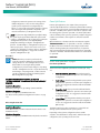
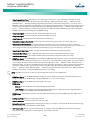
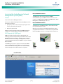
Overview
The NCU performs the following functions:
•
Rectifier Control, including an Energy Optimization Mode
•
Solar Converter and Converter Control
•
System Components Monitoring and System Alarms
Generation (including recording alarms in logs)
•
Operating Data Acquisition and Data Logs
•
Battery Management
The NCU controls the system automatically via configured
parameters.
A User can interface with the NCU locally using the local keypad
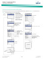
and display or locally/remotely using the Web Interface.
The NCU can also be accessed via SNMP (v2 and v3).
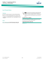
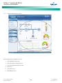
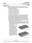
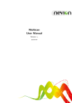
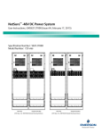
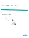
Figure 1 illustrates the various applications that can be used to
interface with the NCU.
Figure 1. Interfacing with the NCU
Spec. No: 1M830BNA, 1M830DNA
Model No: M830B, M830D
[1]
Code: UM1M830BNA
Revision F, July 20, 2015
NetSure™ Control Unit (NCU)
User Manual, UM1M830BNA
Function Descriptions
•
The audible alarm can be silenced by pressing any key on
the NCU local interface pad. The audible alarm is also
silenced if the fault(s) that triggered the alarm clears.
•
An audible alarm cutoff feature can be programmed that
silences the audible alarm after a preset programmable
time period. The audible alarm can also be disabled.
RECTIFIER, SOLAR CONVERTER, AND CONVERTER CONTROL
The NCU controls rectifiers, solar converters, and converters
automatically.
NOTE: Solar Mode has to be enabled for NCU control of solar
converters (see “Enabling Solar Mode” on page 24).
SYSTEM COMPONENTS MONITORING AND SYSTEM ALARMS
GENERATION
The available system alarms can also be mapped to alarm relays
(located on controller interface boards) that can be wired to
external alarm circuits.
OPERATING DATA ACQUISITION AND DATA LOGS
The NCU monitors the components comprising the system (such
as the rectifiers, solar converters, converters, and supervisory
modules) and generates alarms if a fault condition occurs. The
NCU also maintains an alarm history log.
The NCU acquires and analyses real time data from the system's
components such as the rectifiers, converters, and supervisory
modules.
The available system alarms are programmed with an Alarm
Severity Level. Each Alarm Severity Level has different
visual/audible alarm attributes. Available Alarm Severity Levels
and their attributes are listed in Table 1.
The NCU uses this data to process alarms and also records data in
logs. The logs are viewed using the Web Interface and consists of
the following. Logs can be saved in the .html (Web page) or .txt
(text) format.
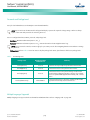
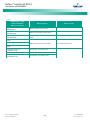
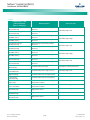
Table 1.
•
•
Alarm Severity Levels
Alarm
Severity
Levels
Red
LED
Yellow
LED
Audible
Alarm
Buzzer
Critical
Alarm (CR)
ON
--
ON
Major
Alarm (MJ)
ON
--
ON
Minor
Alarm (MN)
OFF
ON
OFF
No
Alarm (NA)
OFF
OFF
OFF
Alarm Status Setting: Indicates if the alarm is active or
not active, and the severity level if active. The available
alarm status settings are as follows.
o
Critical Alarm: The fault endangers the power
systems continued function.
o
Major Alarm: The fault reduces the power systems
functionality.
o
Minor Alarm: Special operating condition.
o
No Alarm: The alarm is disabled and no alarm is
given.
Alarm History Log: Records 4000 latest alarms. The Web
Interface displays the latest 500 items.
•
Battery Test Log: Up to ten (10) battery discharge tests
can be recorded.
•
Event Log: Records 500 latest events.
•
Data History Log: Records 60000 latest history data. The
Web Interface displays the latest 500 items.
•
System Log: Records 3000 items in run log. The Web
Interface displays the latest 500 items.
NOTE: For all logs except the Battery Test Log, once maximum
number of log entries is reached, new entries overwrite the
oldest entries.
BATTERY MANAGEMENT
The NCU provides the following battery management functions.
The alarm indicator turns OFF if the fault(s) that triggered
the alarm clears.
Spec. No: 1M830BNA, 1M830DNA
Model No: M830B, M830D
•
[2]
•
Battery Charge Temperature Compensation
•
Battery Equalize Charge
•
Battery Charge Current Limit
•
High and Low Battery Temperature Alarms
•
Battery Thermal Runaway Management (BTRM) Feature
(Reduces Voltage during a High Battery Temperature
Condition)
•
Battery Discharge Test
•
Battery Test Logs (maximum ten [10] tests saved)
Code: UM1M830BNA
Revision F, July 20, 2015
NetSure™ Control Unit (NCU)
User Manual, UM1M830BNA
•
Battery LVD (Low Voltage Disconnect)
•
Battery Capacity Prediction
•
Battery Block and Battery Midpoint Monitoring
•
Enhanced Battery Monitoring with SM-BRC
•
Thermal Runway Detection and Management
DC over or under voltage alarm activates, a low voltage
disconnection occurs, manual mode is entered, or the system
enters the equalize or test modes.
Battery Equalize Charge and Battery Charge Current Limit
The NCU can increase system output voltage for equalizing the
charge on all battery cells of a conventional flooded cell battery, or
for recharging the battery following a commercial power failure.
NOTE: Battery management functions are not available for
NCU configurations that enable NCU capability to receive
status information sent from FIAMM SoNick (Sodium Nickel)
batteries.
The charging function can be initiated cyclically (scheduled),
automatically, or manually.
Refer to the battery manufacturer's instructions for equalize
charging instructions.
Battery Charge Temperature Compensation
The NCU can be programmed to automatically increase or
decrease system output voltage to maintain battery float current
as battery temperature decreases or increases, respectively.
Battery life can be extended when an optimum charge voltage to
the battery with respect to temperature is maintained.
Temperature is monitored by a sensor mounted on the battery.
See your power system documentation for temperature sensor
information. You can also set high and low compensation
temperature alarms.
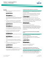
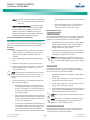
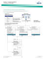
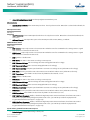
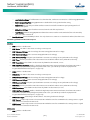
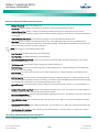
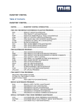
Functional Description (See Figure 3):
Functional Description (See Figure 2):
•
Start of Charging: When the battery charge current
exceeds a preset value for three (3) minutes or if the
calculated battery capacity has decreased to a preset
value (after a commercial AC failure, for example), the
charging function of the NCU is activated. A charging
signal is sent from the NCU to the rectifiers to increase
the voltage up to the battery charging level Vequalize.
•
Battery Current Limitation: After a commercial AC failure
or when some battery cells are permanently damaged,
the current to the batteries can be quite extensive. To
avoid overheating or further damages to the battery, the
NCU limits the battery current to a preset level by limiting
the charging voltage of the rectifiers. Should the battery
current still exceed a higher preset value, an alarm is
issued.
•
End of Charging: When the charging current drops below
a preset value, a defined prolonged charging time is
started before the charging is stopped and the voltage of
the rectifiers return to the float charging level (Vnom). For
safety, there is an equalized charging limit time that
stops the charging after a preset time.
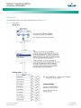
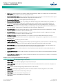
Battery charge temperature compensation adds a correction term,
related to the temperature of the batteries, to the nominal value of
the system voltage. The degree of regulation (TempComp Coeff),
expressed in mV/°C/battery string, can be set per battery
manufacturer recommendations.
To protect batteries and voltage-sensitive loads, compensation is
automatically limited to a maximum of two volts (48V systems) or
one volt (24 volt systems) above or below the nominal output level
(float setting). Temperature compensation can be set to clamp
lower than this by enabling the Temperature Compensation Clamp
feature. When enabled, temperature compensation will clamp if
the battery temperature reaches either the Temp Comp Max
Voltage setting or the Temp Comp Min Voltage setting.
Temperature compensation is automatically disabled if
communication between the controller and all rectifiers is lost, a
Spec. No: 1M830BNA, 1M830DNA
Model No: M830B, M830D
[3]
Code: UM1M830BNA
Revision F, July 20, 2015
NetSure™ Control Unit (NCU)
User Manual, UM1M830BNA
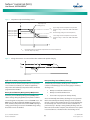
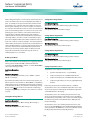
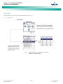
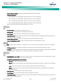
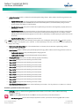
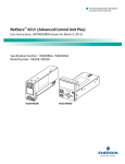
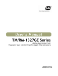
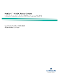
Figure 2. Temperature Compensated Voltage Control
V
TempComp Coeff
setting (mV/°C).
1V Max (24V System)
2V Max (48V System)
1V Max (24V System)
2V Max (48V System)
Vhigh
Upper voltage level where temperature compensation
clamps the voltage. Limited to the TEMP COMP MAX V
setting.
Vnom
Nominal voltage (voltage at nominal temperature).
V low
Lower voltage level where temperature compensation
clamps the voltage. Limited to the TEMP COMP MIN V
setting.
Tnom
Tnom
Nominal temperature (no temperature compensation is done at this temperature).
This is the Temp Comp setting.
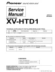
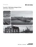
Figure 3. Voltage Characteristics on Commercial AC Failure and Automatic Equalize Charging
High and Low Battery Temperature Alarms
Battery Discharge Test and Battery Test Logs
The NCU can monitor battery temperature via a temperature
sensor mounted on a battery cell. Values for high battery
temperature and low battery temperature alarms can then be
programmed into the NCU.
The NCU can perform battery discharge tests to check the
condition of the battery(s). There are three (3) types of battery
discharge tests:
Battery Thermal Runaway Management (BTRM) Feature
The Battery Thermal Runaway Management (BTRM) feature
reduces voltage during a high battery temperature condition.
You can designate a temperature sensor as the BTRM sensor. The
BTRM sensor has High 2 and High 1 BTRM temperature alarm
limits. If battery temperature exceeds the “BTRM Temp High 2”
setting, system voltage is lowered to the BTRM voltage setting.
This feature can also be disabled.
Spec. No: 1M830BNA, 1M830DNA
Model No: M830B, M830D
•
Battery Test without Constant Current
•
Battery Test with Constant Current
•
Short Time Test (requires two battery shunts)
A User can manually start a battery discharge test or program the
NCU to automatically start battery discharge tests at scheduled
intervals. Twelve (12) Constant Current Tests can be scheduled by
the month-day-year. A Short Time Test can be scheduled to be
performed every 1-365 days. During a battery discharge test, the
NCU controls the rectifiers output to place the entire load or partial
load on the batteries. The NCU monitors the discharge of the
[4]
Code: UM1M830BNA
Revision F, July 20, 2015
NetSure™ Control Unit (NCU)
User Manual, UM1M830BNA
battery and saves the results in a battery test log. The NCU stores
ten (10) battery discharge tests.
Battery LVD (Low Voltage Disconnect)
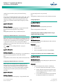
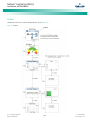
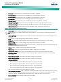
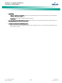
Functional Description:
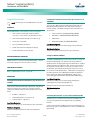
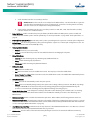
For manual battery discharge tests as well as for scheduled battery
discharge tests, the following parameters must be set: End Test
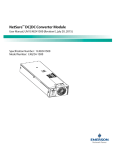
Voltage, End Test Time, and End Test Capacity. See Figure 4.
Figure 4. Battery Test Diagram
To prevent serious damage to the batteries during a commercial
AC power failure, the batteries can be disconnected by voltage or
time control.
The batteries are reconnected automatically when commercial AC
power is restored and a predetermined DC voltage level is reached.
•
Voltage Controlled Disconnection: When the set voltage
level is reached, the batteries are disconnected.
•
Time Controlled Disconnection: After the Mains Failure
alarm occurs the batteries will disconnect after the set
time has elapsed.
Battery Capacity Prediction
The NCU can predict battery capacity.
Battery Block and Battery Midpoint Monitoring
Battery Discharge Test Sequence:
•
For a Constant Current Test, the output voltage of the
rectifiers is reduced so that the batteries supply the
preset Constant Current Test Current to the load.
•
If Constant Current is disabled, then the current being
delivered by the batteries will be dependent on the load.
•
For a Short Time Test, the output voltage of the rectifiers
is reduced so that only the batteries power the load. If
the batteries fail, the rectifiers power the load.
•
The NCU can monitor battery blocks (12 V blocks) or midpoint
battery voltage of battery strings connected to the EIB (Controller
Extended Interface Board) assembly. An alarm is issued when
either battery block voltage or battery midpoint voltage is
abnormal.
Enhanced Battery Monitoring with SM-BRC
When connected to an SM-BRC, the NCU provides enhanced
battery monitoring.
The battery test continues until one of the following
occurs:
Thermal Runaway Detection and Management
a.
The preset End Test Time, see Figure 4, expires. The
battery has passed the test.
Functional Description:
b.
The battery capacity drops below the preset End
Test Capacity. The battery has passed the test.
c.
The battery voltage drops below the preset End Test
Voltage (Vend) (see Figure 4). The battery has not
passed the test and the test is interrupted. A bad
battery alarm is activated.
•
A battery test alarm is active during a battery discharge
test.
•
If the battery has not passed the test, a bad battery alarm
is activated.
•
After the battery discharge test, the output voltage of
the rectifiers increases so that the rectifiers supply the
system and charge the batteries.
NOTE: A procedure for performing a manual battery discharge
test is provided on page 28.
Spec. No: 1M830BNA, 1M830DNA
Model No: M830B, M830D
[5]
The system uses several control mechanisms to avoid thermal
runaway.
•
During a short high rate discharge, the batteries will
normally get hot. The NCU takes this into consideration.
After completion of the discharge duty, the batteries are
recharged with a limited current to avoid heating the
batteries any further.
•
The temperature of the batteries can be monitored, and
the NCU sets the charge voltage appropriately, as
previously described under “Battery Charge Temperature
Compensation” on page 3.
•
In addition to battery temperature compensation, if
battery temperature rises above a set temperature limit,
the system stops battery charging completely by
lowering the output voltage to the “BTRM Voltage”
setting. This allows the batteries to cool down. The
system also provides alarm notification of this
Code: UM1M830BNA
Revision F, July 20, 2015
NetSure™ Control Unit (NCU)
User Manual, UM1M830BNA
occurrence. Power supplied to customer equipment is
not interrupted.
•
j.
Any one LVD disconnect.
k.
Battery is in charge or discharge, as defined below:
The battery LVD circuits can be programmed to open
(disconnect) if a high temperature event occurs (HTDHigh Temperature Disconnect). The contactor(s) open
when battery temperature rises above a programmable
value and close again when battery temperature falls
below another programmable value.
ENERGY MANAGEMENT
l.
Energy Management consists of an Energy Optimization Mode.
n.
The NCU provides an Energy Optimization Mode (ECO) function.
Energy Optimization permits an installation to only operate
rectifiers as needed to maintain the load and keep batteries in a
fully charged condition. As load increases, Energy Optimization
turns on additional rectifiers as needed to maintain the load. As
load decreases, Energy Optimization places rectifiers in standby to
conserve energy usage. Rectifiers which are always operating to
maintain any load requirements are cycled through the group of
rectifiers controlled by this feature to provide uniform operating
times for each rectifier.
ALERT! The Energy Optimization Mode should NOT be
used in systems that operate without batteries.
The following operating conditions apply:
1.
The ECO mode is only enabled upon normal system
operation. If any of the following alarms occurs, the
system cannot enter or will exit the ECO mode.
a.
Current imbalance (only when imbalance current
protection is enabled).
b.
AC fail.
c.
Any one rectifier over temp.
d.
Any one rectifier AC fail.
e.
Any one rectifier fault.
f.
Any one rectifier over voltage.
g.
Any one rectifier fan fault.
h.
Any one rectifier no response.
i.
Any one battery fuse open.
Spec. No: 1M830BNA, 1M830DNA
Model No: M830B, M830D
Battery current > [battery rated capacity ×
0.005], or battery current > 5A means battery in
charge.
•
Battery current < [battery rated capacity
× -0.003], or battery current < -2A means
battery in discharge.
Under voltage.
m. Any one rectifier in power limit.
Energy Optimization Mode
Alert
•
Any one rectifier in current limit mode.
2.
The system load cannot exceed the system energy saving
point (default value is 45%). Otherwise the system
cannot enter or will exit the ECO mode.
3.
When the rectifier load exceeds its optimal operating
point, the system will exit the ECO mode and the
controller will recalculate and then turn off any
unnecessary rectifiers. After that, the system can enter
the ECO mode again.
4.
If the system enters the ECO mode and then exits for five
consecutive times within one hour, an abnormal alarm
(ECO Cycle Alarm) will be generated and the system can
no longer enter the ECO mode until the ECO Cycle Alarm
is cleared manually or retires automatically after 24
hours.
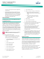
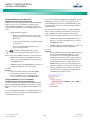
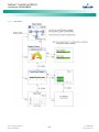
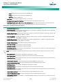
POWER SPLIT FEATURE
The Power Split feature allows you to connect the power system
controlled via the NCU to an existing DC power system instead of
extending or completely replacing the existing DC power system.
The power system controlled via the NCU functions as “System A”
to share load (split output) with the existing system (“System B”)
that requires expansion. The NCU does not require
communication with the “System B’s” controller.
The Power Split feature provides for the sharing of total load in a
controlled manner between the paralleled power systems.
When Power Split is programmed, the NCU adjusts rectifier output
voltage per load demands to ensure proper sharing between
“System A” and “System B”. See Figure 5.
[6]
Code: UM1M830BNA
Revision F, July 20, 2015
NetSure™ Control Unit (NCU)
User Manual, UM1M830BNA
Figure 5. Power Split Feature
Spec. No: 1M830BNA, 1M830DNA
Model No: M830B, M830D
[7]
Code: UM1M830BNA
Revision F, July 20, 2015
NetSure™ Control Unit (NCU)
User Manual, UM1M830BNA
DIESEL MANAGEMENT FEATURE
The Diesel Management feature is available when an SM-AC
supervisory module is connected to the NCU. The Diesel
Management feature consists of a Diesel Test. The Diesel Test can
be performed at specific intervals or a User can manually start the
Diesel Test. The NCU records the test results.
SUPERVISORY MODULE (SM MODULES) MONITORING
Various devices (supervisory modules) can be connected to the
NCU to extend its monitoring capabilities.
As the two types of control are specific to the hardware
configuration of the site, the Fixed Daily Time or Capacity
Discharge is a User selectable option on installation.
Hybrid Operation
Generator Control: A potential free relay contact output from the
NCU interface board controls the start and stop of the diesel
generator. The signal will be generated by the NCU and operates
according to the Hybrid software mode of operation. The control
logic is as follows:
HYBRID CONTROL FUNCTION (SUPPORTING GENERATOR,
SOLAR AND WIND ENERGY INPUT, AND OPTIMIZATION)
Hybrid Control is designed for use in new installations or as an
upgrade of existing sites powered by a diesel generator(s) when
grid power is not available. The Hybrid control is also applicable to
sites with highly unreliable or frequently unavailable grid power
connection. The primary power source is still considered to be the
diesel generator(s). Since grid power is always given priority, the
primary power source is still considered to be the grid power.
NOTE: The Hybrid Control function requires a specific
configuration. Hybrid Control menus will not normally be
displayed unless your NCU has been configured by Emerson for
this function. Contact Emerson for a Hybrid Control
configuration.
General
Hybrid Control allows the option of selecting one of the following:
Fixed Daily Time based operation or Capacity Discharge based
operation.
Fixed Daily Time based operation is intended to be used with a
combination of AC powered active cooling (air conditioners) and
DC powered cooling (heat exchangers, etc.). The cycle period is
synchronized to the 24hrs day-night cycle. It makes optimum use
of the different temperature conditions during the day and the
night in order to facilitate Hybrid fuel saving operation.
Capacity Discharge based operation is intended for sites utilizing
only DC powered cooling (heat exchangers, etc.). The cycle period
is determined by User selectable depth of discharge (DOD) of the
batteries per cycle, and associated recharge time. It provides
optimum Hybrid fuel saving operation.
Operation from Grid Power is performed with both Fixed Daily
Time and Capacity Discharge modes of operation. Grid power is
always given priority when available.
Spec. No: 1M830BNA, 1M830DNA
Model No: M830B, M830D
•
Energized Output Relay - Generator OFF
•
De-energized Output Relay – Generator ON
This is a fail-safe logic to ensure generator operation in all cases
where power or control to the relays is lost.
In addition, the type of signal to the Generator can be selected as
N/O (Normally Open) or N/C (Normally Closed) by selecting the
relevant output pins of the control relay.
Number of Generator Control Outputs: The NCU Hybrid software
can control one or two generators. Each generator control is
designated as DG1 or DG2 output. The User can select DG1, or
DG2, or DG1 and DG2. When both are selected they will be
alternatively used (two generators operation).
Diesel Fail Alarm: A diesel fail alarm will be generated if the Diesel
Generator ON signal fails to bring the generator to operation and
provide the system with AC power. Alarm will be triggered after
60 seconds (default value, settable) from ON signal. If two
generator operation is selected, the second Diesel Generator ON
signal will be activated simultaneously with the Diesel Fail alarm.
Battery Fuse Trip Alarm: In the event of a Battery Fuse trip
condition, an alarm will be generated.
Under Voltage Alarms:
•
Under Voltage Alarm 1: If voltage decreases below the
Under Voltage Alarm 1 setting, an alarm is raised.
•
Under Voltage Alarm 2: If voltage decreases below the
Under Voltage Alarm 2 setting, the Diesel Generator is
started and an alarm is raised.
LVD 1: Normal loads are disconnected.
LVD 2: Priority loads are disconnected.
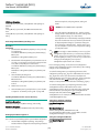
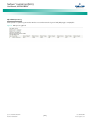
Charge Voltage: Refer to Figure 6.
Equalize Charge: The battery will be recharged at the equalize
voltage. This is the voltage set in the initial phase of battery
recharge. See Figure 6.
[8]
Code: UM1M830BNA
Revision F, July 20, 2015
NetSure™ Control Unit (NCU)
User Manual, UM1M830BNA
As the voltage limit is reached, the charge current is gradually
reduced – this effect is known as current tail. When the current tail
falls below a threshold level, additional equalize charge time is
added and then the recharge ends.
The equalize charge current tail threshold is settable from 0.01 to
0.05. Default setting is 0.02 (2A per 100Ah). The additional
equalize charge time is settable from 0 hours to 7 hours (settable
in minutes from 0 to 720), default setting is 4 hours. The duration
of the equalize charge is the time from the start of the recharge to
the end of the additional time. (Maximum charge time,
determined from the time charge starts, is settable in the range of
5hours to 24 hours).
The end of recharge is determined by a three (3) step approach:
•
Step 2 - charge current tail threshold is reached.
•
Step 3 - additional charge time is completed.
During discharge, over temperature and under voltage conditions
will interrupt the discharge and change the operation to charge
with the Diesel Generator ON.
Over Temperature: The diesel generator will start and run for a
period before it is stopped again. The run time is User selectable in
the range 30 to 120 minutes, default setting is 60 minutes.
Temperature is referenced to cabinet/shelter ambient
temperature sensor connected to controller, not battery
temperature. Over temperature start can be disabled completely
from the Settings menu.
Under Voltage: The under voltage start is triggered by under
voltage alarm 2 voltage settings.
Step1 - calculated battery capacity exceeds 90%.
Calculation is performed by measurement of battery
current and time, in Ah.
•
Early Termination of the Discharge Periods
The diesel generator will start and run until the normal recharge
cycle is due to finish depending on selected mode of operation.
Under Voltage with Fixed Daily Time: If the normal recharge cycle
is from 7am until 7pm and under voltage has started the Diesel
Generator at 5:30am, the effective recharge will be from 5:30am
until 7pm.
Float Charge: Default float voltage is 54.0V at 20°C with a
temperature compensation of 72mV per °C.
If battery temperature exceeds 38°C, the charge voltage is reduced
to 51V to reduce gassing and prevent thermal runaway. The same
is applicable as well for equalizing charge.
Equalizing Charge Cycle: As the cyclic use does not ensure
complete battery recharge after every cycle, an equalizing charge
cycle is added. The equalizing cycle will occur up to four times a
month, settable for every 7 to 60 days intervals. Start date and
time is settable. Equalizing charge time is 20 hours independent of
discharge time setting. Equalizing charge is performed at equalize
voltage until end of additional equalize time and thereafter at float
voltage for the remaining time. Also see Figure 6.
Equalize charge independently settable 0-720 min (already set in
equalize charge).
Figure 6. Charge Voltage
Under Voltage with Capacity Discharge: If this mode is selected,
the recharge will terminate.
Operation with Grid Power
Grid power is always used when available. If grid power becomes
available during battery discharge, the discharge cycle is
terminated and recharge cycle is initiated. If grid power becomes
available during diesel generator operation, the diesel generator is
switched OFF and operations continue on grid power.
Battery Recharge with Grid Power: Battery recharge with grid
power can start from the beginning (when grid power becomes
available during battery discharge) or can continue from diesel
generator recharge, depending on the timing. In both cases, the
recharge process will follow the recharge profile shown in Figure 6.
If battery becomes fully recharged and grid power is still present,
the operations will continue to be powered from grid and no
battery discharge will be initiated for the duration of grid
availability. In this case, battery voltage will revert back to Float
voltage.
Battery Discharge after Grid Failure: At the point of grid power
failure, the battery capacity is unknown as these events occur in
random manner. For the purpose of maximizing the use of grid
power and in anticipation of grid power becoming available again,
the Hybrid operation will continue with battery discharge cycle.
Discharge will continue until:
•
Spec. No: 1M830BNA, 1M830DNA
Model No: M830B, M830D
[9]
The preset discharge time elapses (Fixed Daily Time)
Code: UM1M830BNA
Revision F, July 20, 2015
NetSure™ Control Unit (NCU)
User Manual, UM1M830BNA
•
The preset DOD is reached (Capacity Discharge)
In both cases, the discharge can be terminated earlier as described
in “Early Termination of the Discharge Periods” on page 9.
Relay Assignment – when in Hybrid Mode
Relay 1: Generator Alarm.
No Generator Voltage Alarm. No AC supply, 60 sec delay.
Relay 2: Battery Alarms.
Logic alarm generated from: under voltage 1, under voltage 2,
LVD1, LVD2, battery high temp, battery very high temp,
overvoltage 1, overvoltage 2, battery temp sensor fail, battery fuse
alarms and high load alarm.
Relay 3: Rectifier Alarms.
Logic alarm generated from: multiple rectifier fail, rectifier fail,
rectifier fan failure, rectifier HVSD, rectifier AC failure and rectifier
not responding.
Relay 4: System Alarms.
Logic alarm generated from: load fuse alarms, high ambient
temperature, ambient temp sensor fail; smoke detected, and
water detection.
Relay 5: Generator Run at High Temp.
Output to intelligent cooling devices linked to AC supply (DG run).
Relay 6: Intruder Alarm.
Alarm triggered by dry contact door/motion sensor.
Relay 7: Diesel 1 in Operation.
Output to DG1 on site. DG is set on for the duration of the signal.
Relay 8: Diesel 2 in operation.
Output to DG2 on site. DG is set on for the duration of the signal.
Fixed Daily
In this mode of operation, the total duration of a complete cycle is
24hrs. This duration is necessary as the operation is synchronized
with day-night temperature pattern. When an extended recharge
cycle is required, its termination will still follow the 24hrs schedule.
Cycle Duration: A complete cycle consists of discharge and charge
periods during the combined total of 24hrs. The discharge period
starts at 7pm. It is then followed by recharge period (Diesel
Generator ON) for the remainder of the 24hrs. The discharge time
is User selectable in the range 1hrs to 22hrs, default setting is
12hrs.
Discharge: The discharge start time and duration are settable.
Discharge period starts at 7pm. The discharge time is User
selectable in the range 1hours to 22hours, default setting is 12
hours.
Spec. No: 1M830BNA, 1M830DNA
Model No: M830B, M830D
Recharge: Recharge period (Diesel Generator ON) follows after
discharge for the remainder of the 24hrs. Recharge is performed
at equalize voltage until added equalize time elapses and at float
voltage for the remaining charge time.
High Load Alarm: In order to identify conditions where the load
requirements are exceeding the dimensioning of the Hybrid site,
an alarm will be generated. The alarm will be triggered when the
maximum capacity per discharge cycle is exceeded. The threshold
value will be set as default to 40% of battery capacity. It will
require capacity measurement per cycle. The alarm will be set
once the high load threshold value is reached and is reset at the
beginning of the next discharge period. This alarm will help the
User identify the root cause of the under voltage condition: high
demand load, the loss of capacity due to battery aging, or
insufficient charge capacity.
Capacity Discharge
The cycle period is determined by User selectable capacity
discharge of the batteries and associated recharge times. The
cycle repeats continuously. It does not follow a 24hrs pattern.
Capacity Discharge and Recharge: The battery discharge period is
determined by the percentage of the nominal battery capacity
[Ah] that will be discharged per cycle.
The depth of discharge [DOD] per cycle is User selectable in the
range 20% to 80%. Default setting is 60%. The value is set as
battery capacity at the end of each discharge period. Therefore, if
a 60% discharge is chosen, the discharge value is set to 40%.
The time to recharge to full battery capacity depends on battery
capacity at the start of the charge cycle and the available recharge
current.
When the additional charge time has been reached; the generator
will be stopped, the recharge cycle will end, and discharge cycle
will be initiated.
For practical purposes, the battery capacity at the end of every
recharge period is set to 100% as long as Step1, Step 2, and Step 3
have elapsed.
If end of charge is not reached within the set maximum hours, the
recharge will be terminated and discharge cycle will be initiated.
MAXIMUM CURRENT LIMIT FUNCTION
The current available from the rectifiers can be limited (in AMPS)
from 10% to 121% of combined rectifier capacity. The factory
setting is 121% unless otherwise specified. The current available
from the solar converters can be limited (in AMPS) from 0% to
121% of combined solar converter capacity. The factory setting is
121% unless otherwise specified. The current available from the
converters can be programmed (in AMPS) from 50% to 116% of
[10]
Code: UM1M830BNA
Revision F, July 20, 2015
NetSure™ Control Unit (NCU)
User Manual, UM1M830BNA
(13) dry relay outputs. Every relay output has a set of NC
(normally close) and NO (normally open) contacts.
combined converter capacity. The factory setting is 116% unless
otherwise specified. Refer to the NCU Configuration Drawing (C–
drawing) supplied with your system documentation for your
system’s settings.
The relay outputs can be connected to customer external
alarm circuits. Each relay output can be configured to
change state when one or more alarm events occur.
See also “Checking the Controller’s Current Limit Point after
Adding or Removing a Rectifier, Solar Converter, or Converter
Module” on page 23.
The relay outputs can also be connected to customer
external equipment, so that the relay output can control
or interface with the customer external equipment.
COMMUNICATIONS FUNCTION
The NCU is able to communicate with different equipment or,
connect to different equipment for communication. See Figure 7.
a.
10M/100M Ethernet Port: The NCU can communicate
with a supervisory computer or other devices through its
10M/100M Ethernet port. The communication cable
shall be a shielded cable. The Ethernet port is located on
the front panel of the NCU. This port supports Dynamic
Host Configuration Protocol (DHCP) function.
c.
IB4 (Interface Board 4): Some systems may have an IB4
board. The IB4 board is a USB to LAN converter for the
NCU, which includes a USB and an Ethernet port. The IB4
board is connected to the NCU’s backplane connector
(USB) via a factory provided cable. Refer to your system’s
documentation for location of the IB4 board (if
furnished).
d.
RS-485 Port: The NCU can communicate with an SM-AC,
SM-Bat, or SMIO through the RS-485 port. The RS-485
port uses the parameters 19200, n, 8, 1.
e.
Modbus Protocol: The NCU can communicate with an AC
Meter using the Modbus protocol.
NOTE: Some systems may have an IB4 board with a second
Ethernet port. The IB4 board is connected to the NCU’s
backplane connector (USB) via a factory provided cable. Refer
to your system’s documentation for location of the IB4 board
(if furnished).
b.
IB (Interface Board) and EIB (Extended Interface Board):
Some systems may have an IB (Interface Board) and/or
EIB (Extended Interface Board) connected to the NCU.
Combinations of IBs and EIBs can provide up to thirteen
FIAMM SoNick (SODIUM NICKEL) BATTERY INTERFACE
If a special configuration file is furnished, the NCU has capability to
receive status information sent from FIAMM SoNick (Sodium
Nickel) batteries.
Figure 7. The Controller Perspective
Spec. No: 1M830BNA, 1M830DNA
Model No: M830B, M830D
[11]
Code: UM1M830BNA
Revision F, July 20, 2015
NetSure™ Control Unit (NCU)
User Manual, UM1M830BNA
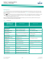
Operation
Local Indicators
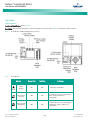
Location and Identification: Refer to Figure 8.
Description: There are three (3) indicators located on the NCU’s front panel. Refer to Table 2 for the function of the indicators.
Figure 8. Local Indicators and Menu Navigation Keys Locations
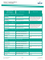
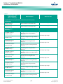
Table 2.
Local Indicators
Indicator
Normal State
Fault State
Status
(Green)
On
Off
No input power to the NCU.
Minor Alarm
(Yellow)
Off
On
The system has one or more active Minor
alarms. Alarm conditions are
programmable.
Major or Critical
Alarm (Red)
Off
On
The system has one or more active Major or
Critical alarms. Alarm conditions are
programmable.
Spec. No: 1M830BNA, 1M830DNA
Model No: M830B, M830D
[12]
Fault Cause
Code: UM1M830BNA
Revision F, July 20, 2015
NetSure™ Control Unit (NCU)
User Manual, UM1M830BNA
Passwords and Privilege Levels
Users (for local and Web access to the NCU) are set via the Web Interface.
NOTE: Anyone can browse the NCU via the local keypad and display. A password is required to change settings. Web access always
requires a User name and password to be entered to gain access.
Users are configured with a User Name, password, and privilege level.
User Name: Maximum 8 Characters (0-9, a-z, A-Z, _).
Password: Maximum 13 Characters (0-9, a-z, A-Z, _). Passwords must be at least six (6) characters long.
NOTE: Once a password is entered, it remains in effect for a preset time period to allow navigating between menus without re-entering
the password.
Privilege Level: Refer to Table 3. A User has access to his/her privilege level menus, plus all menus of the lesser privilege levels.
Table 3.
User Privilege Levels
Privilege Level
Default User Name
and Password
Level A (Browser)
none set
The User can only read (browse) information in the menus.
Level B (Operator)
none set
The User has access to the system "Control" menus.
Level C (Engineer)
none set
The User has access to the system "Settings" menus and can
download the configuration package. The User does not have
access to update the OS application and modify, add, or delete
Users.
Level D (Administrator)
admin, 640275
The User has full access to all menus; including update the OS
application and modify, add, and delete Users.
Authority
Multiple Languages Supported
Multiple languages are supported in the Local Interface and Web Interface. Refer to “Language Tab” on page 156.
Spec. No: 1M830BNA, 1M830DNA
Model No: M830B, M830D
[13]
Code: UM1M830BNA
Revision F, July 20, 2015
NetSure™ Control Unit (NCU)
User Manual, UM1M830BNA
Using the Local Keypad and Display
LOCAL MENU NAVIGATION KEYS AND LOCAL DISPLAY
Location and Identification: Refer to Figure 8.
Description: There are four (4) menu navigation keys and a local display located on the NCU’s front panel. Refer to Table 4 for the
function of the menu navigation keys.
NOTE: When the local display is lit, if no button is pushed for eight (8) minutes, the backlight of the local display extinguishes and the
NCU returns to the Main Menu. Press any key to re-activate the local display.
Table 4.
Local Menu Navigation Keys
Key Symbol
Key Name
ESC
Escape
Press this key to go back to a previous
menu or to cancel setting a parameter.
ENT
Enter
Press this key to go forward to the next
menu, to select a parameter to edit, or
to validate a parameter setting change.
Up Arrow
Down Arrow
Function
Press ESC and ENT together to reset the
NCU, then press ENT to accept or ESC to
cancel.
Press the up or down arrow keys to scroll
through the menus or to change the
value of a parameter.
--
Press any key to silence an audible alarm.
LOCAL DISPLAY MENUS
Refer to “Local Display Menus” on page 72.
NOTE: A valid password is required to access menus that allow changing any power system parameter.
Navigating the Menus
To Select a Sub-Menu:
Press the UP and DOWN keys to highlight the desired sub-menu.
Press the ENT key to enter the selected sub-menu.
To Select a User and Enter a Password:
To select a User, use the UP and DOWN keys to move the cursor to the Select User field. Press ENT. Use the UP and DOWN keys to select
a User previously programmed into the NCU. Press ENT to select the User. Note that only Users programmed into the NCU are shown.
Users are programmed via the Web Interface.
To enter a password, use the UP and DOWN keys to move the cursor to the Enter Password field. Press ENT. Use the UP and DOWN keys
to choose a character. Press ENT to accept and move to the next character. Continue this process until all characters are entered. Press
ENT again to accept the password.
To Change a Parameter:
Press the UP and DOWN keys to move up and down the list of parameters.
Press ENT to select the parameter.
Press the UP and DOWN keys to change the parameter.
Press ENT to make the change. Press ESC to cancel the change.
Spec. No: 1M830BNA, 1M830DNA
Model No: M830B, M830D
[14]
Code: UM1M830BNA
Revision F, July 20, 2015
NetSure™ Control Unit (NCU)
User Manual, UM1M830BNA
Using the Web Interface
Setting IPv6 Communications Parameters (if controller not set
as DHCPv6)
NOTE: The NCU supports a 10/100M Ethernet connection.
The controller’s IPv6 parameters (IPv6 address, IPv6 prefix, and
IPv6 gateway address) must be set to match your company’s
network settings. The default settings for these parameters are
shown below.
OVERVIEW
Via the Web Interface, a User (with proper access level) can:
View real-time operating information (rectifiers,
converters, solar converters, AC, DC, batteries, etc.).
•
Link-Local Address: fe80:209:f5ff:fe09:1002/64
•
IPv6 Address: 20fa:fffd:fffc:fffb:fffa:fff9:fff8:fff7
•
View and download information recorded in logs.
•
IPv6 Prefix: 0
•
Send control commands.
•
IPv6 Gateway: 20fa:1:fffe:ffff:fffe:fffd:ffff:fffe
•
Set programmable parameters.
•
Download and upload configuration package.
•
Download firmware to the controller.
•
Local Menu Navigation:
Main Menu / Settings Icon / Comm Settings / enter parameters.
Web Menu Navigation:
Advance Settings Menu / Ethernet Tab / enter parameters.
MULTIPLE BROWSERS SUPPORTED
Setting for DHCP and DHCPv6
Multiple browsers are supported in the Web Interface. The User
can use Internet Explorer, Chrome, Safari, or Firefox.
PROCEDURES
The DHCP and DHCPv6 functions allow the controller to acquire an
IP address automatically. This function can only be enabled or
disabled via the local display and keypad. If this function is enabled
and the acquisition of an IP address fails, an alarm is generated. If
the acquisition of an IP address is successful, you need to record
the IP address automatically acquired by the controller to access
the controller via the Web Interface. This IP address is displayed on
the main system info screen (Main Menu / ESC) in the IP Address
field or in the local display menu (Main Menu / Settings Icon /
Comm Settings) in the IP Address field below the DHCP setting.
Setting IPv4 Communications Parameters (if controller not set
as DHCP)
Local Menu Navigation:
Main Menu / Settings Icon / Comm Settings / DHCP (set to
enabled) (can also view acquired IP address).
WEB INTERFACE SCREENS
Refer to “Web Interface Screens” on page 95.
Main Menu / ESC (to view acquired IP address).
The controller’s IPv4 parameters (IP, subnet mask, and gateway
addresses) must be set to match your company’s network
settings. The default settings for these parameters are shown
below.
•
IP Address: 192.168.1.2
•
Subnet Mask Address: 255.255.255.0
•
Gateway Address: 192.168.1.1
Web Menu Navigation:
None.
Connecting the Controller to your Local Area Network (LAN)
An Ethernet port is located on the front panel of the NCU. This
port supports Dynamic Host Configuration Protocol (DHCP)
function.
Local Menu Navigation:
Main Menu / Settings Icon / Comm Settings / enter parameters.
Some systems may have an IB4 board with a second Ethernet port.
Refer to your system’s documentation for location of the IB4 board
(if furnished).
Web Menu Navigation:
Advance Settings Menu / Ethernet Tab / enter parameters.
Spec. No: 1M830BNA, 1M830DNA
Model No: M830B, M830D
[15]
Code: UM1M830BNA
Revision F, July 20, 2015
NetSure™ Control Unit (NCU)
User Manual, UM1M830BNA
•
If your system does not have an IB4 board, connect the
Local Area Network (LAN) to the NCU’s front panel port.
This port can be assigned an IP address or can be set for
DHCP (see above).
•
If your system has an IB4 board, connect the Local Area
Network (LAN) to the IB4 board port. The IB4 board port
can be configured as a DHCP client or can be configured
with an IP address. If it is a DHCP client, it will get its IP
address from a DHCP server on the network.
parameters were not changed, they should be at the
default values as shown in the example section
below.
IPv4
IP Address:
Subnet Mask:
Default Gateway:
Example:
IP Address:
192.168.1.2
Subnet Mask:
255.255.255.0
Default Gateway: 192.168.1.1
Connecting a Local Computer Directly to the Controller
IPv6
IPv6 Address:
IPv6 Prefix:
IPv6 Gateway:
An Ethernet port is located on the front panel of the NCU. This
port supports Dynamic Host Configuration Protocol (DHCP)
function.
Example:
IPv6 Address:
IPv6 Prefix:
IPv6 Gateway:
Some systems may have an IB4 board with a second Ethernet port.
Refer to your system’s documentation for location of the IB4 board
(if furnished).
d.
Procedure
1.
Before connecting your computer directly to the
controller’s Ethernet port, if your system does not have
an IB4 board, use the following procedure to record your
computer’s network settings (so they can be returned to
these values when done) and then change these settings
in your computer to match the communications settings
programmed in the controller. (If your system has an IB4
board, go to step 2. You do not need to change the
settings in your computer.)
b.
IP Address:
Subnet Mask:
Default Gateway:
Example:
IP Address:
192.168.1.3
Subnet Mask:
255.255.255.0
Default Gateway: 192.168.1.1
IPv6
Record your computer’s network settings by
launching Control Panel in your computer. Navigate
through Network and Sharing Center Local Area
Connection Properties Internet Protocol
Version 4 (TCP/IPV4) Properties.
IPv6 Address:
IPv6 Prefix:
IPv6 Gateway:
Example:
IPv6 Address:
IPv6 Prefix:
IPv6 Gateway:
Record whether the "Obtain an IP address
automatically" or "Use the following IP address"
button is selected. If "Use the following IP address"
button is selected, also record the following:
e.
IP Address:
Subnet Mask:
Default Gateway:
c.
2.
Record your controller’s network settings by
navigating the controller’s local display panel to
Main Menu / Settings Icon / Comm Settings. Record
the following controller’s IP parameters. If these
Spec. No: 1M830BNA, 1M830DNA
Model No: M830B, M830D
Change your local computer’s network settings
using the information you acquired in the above
step, except that the last part of the IP address needs
to be replaced with any different number.
IPv4
NOTE: Windows 7 operating system is used in this procedure,
other operating systems are similar.
a.
20fa:fffd:fffc:fffb:fffa:fff9:fff8:fff7
0
20fa:1:fffe:ffff:fffe:fffd:ffff:fffe
Select OK. Note that you may have to reboot your
local computer for the settings to take effect. Follow
any instruction you see on the screen.
Connect your computer directly to the controller’s
Ethernet port (RJ-45 jack located on the front of the
controller). See Figure 8.
a.
[16]
20fa:fffd:fffc:fffb:fffa:fff9:fff8:fff7
0
20fa:1:fffe:ffff:fffe:fffd:ffff:fffe
If your system does not have an IB4 board, the NCU’s
front panel port is configured with an IP address.
Default is 192.168.1.2. This is the address you will
Code: UM1M830BNA
Revision F, July 20, 2015
NetSure™ Control Unit (NCU)
User Manual, UM1M830BNA
type into your Web browser to access the NCU’s
Web Interface. You will also have to set the
properties on your computer (refer to the previous
procedure in step 1).
b.
3.
If your system has an IB4 board, refer to the
following.
•
The NCU’s front panel port will have the
following IPv4 Address: 192.168.100.100.
Enter the address 192.168.100.100 in your Web
browser to access the NCU’s Web Interface via
IPv4.
•
The NCU’s front panel port will have the
following IPv6 Address. IPv6 Link-Local Address:
fe80::209:f5ff:fe09:1002/64 or IPv6 Address:
20fa:fffd:fffc:fffb:fffa:fff9:fff8:fff7. Enter the
IPv6 Link-Local Address:
[fe80::209:f5ff:fe09:1002/64] or IPv6 Address:
[20fa:fffd:fffc:fffb:fffa:fff9:fff8:fff7].
3.
When finished, disconnect your computer from the NCU
and, if necessary, reset your computer network settings
as recorded in step 1.
Click on the LAN Settings... button. The following window
opens. In the LAN Settings window, uncheck the Proxy
Server box and click OK.
Disabling Proxy Server Settings to Enable a Connection to the
Controller over an Intranet Network (if required)
NOTE: This procedure needs to be performed only when the
controller is connected to an Intranet and the User’s computer
is set to access the Intranet through a proxy server. Note that
if the controller is connected to the Internet and the User’s
computer is connected to an Intranet, the User may not be
able to disable the proxy server and access the controller.
If the controller’s Ethernet port is connected to your company’s
Intranet Network and your computer is also connected to the
Intranet Network but requires access via a proxy server, you must
disable the proxy server settings to access the controller. Follow
the procedure below to disable the proxy server settings.
Procedure
NOTE: Internet Explorer is used in this procedure, other
browsers are similar.
1.
Launch “Internet Explorer”.
2.
Select Internet Options from the Tools menu. The
“Internet Options” window opens. In the “Internet
Options” window, select the Connections tab.
Spec. No: 1M830BNA, 1M830DNA
Model No: M830B, M830D
Internet Security Settings for Loading Files
or Downloading Files into the NCU
Your computer’s security settings may prevent you from loading
files or downloading files into the NCU. Refer to the following
procedure to set your computer’s security settings to allow for
this.
Procedure
NOTE: Internet Explorer is used in this procedure, other
browsers are similar.
1.
[17]
Launch “Internet Explorer”.
Code: UM1M830BNA
Revision F, July 20, 2015
NetSure™ Control Unit (NCU)
User Manual, UM1M830BNA
2.
3.
Select Internet Options from the Tools menu. The
“Internet Options” window opens. In the “Internet
Options” window, select the General tab.
4.
In the “Internet Options” window, select the Security tab.
5.
Click on Trusted sites. With “Trusted sites” selected, click
“Sites”. The following window opens. Uncheck the
“Require server verification (https:) for all sites in the
zone:” box if https is not being used.
6.
In the Trusted sites window, type or copy the NCU URL in
the “Add this website to the zone:” box.
Under “Browsing History”, click on the Settings button.
The following window opens. In the Settings window,
choose “Every time I visit the webpage” and click OK.
Spec. No: 1M830BNA, 1M830DNA
Model No: M830B, M830D
[18]
Code: UM1M830BNA
Revision F, July 20, 2015
NetSure™ Control Unit (NCU)
User Manual, UM1M830BNA
NOTE: By default, the “User Name” is "admin" and the
“Password” is “640275”. It is recommended to change the
default password the first time you login using the default User
Name admin.
NOTE: Before entering a User Name and password, you can
select a local language that the Web Interface menus use from
those listed in the top right corner of the login window. See
“Language Tab” on page 156.
7.
Click Add. The NCU URL is listed in the Websites: box.
Click Close.
3.
After entering a valid User Name and Password and
clicking LOGIN, the Web Interface "HOMEPAGE" window
opens. Refer to “Web Interface Screens” on page 95.
You can program a “Forgot Password” feature. Once
programmed, if you forgot your password, click Forgot Password in
the login screen. A "Find Password" window opens. Enter your
User Name and click Find Password. The controller sends the
password to the email address programmed for this User Name.
Logging into the Controller
Procedure
•
Internet Explorer, version 6 or newer, is supported (IE 8.0 is
recommended). Chrome, Safari, and Firefox are also supported.
1.
In your browser, enter http:// and the controller’s IP
address (see also step 2 under “Connecting a Local
Computer Directly to the Controller” on page 16) and
press ENTER. If your site requires secure HTTP and you
were furnished with an NCU configuration with secure
HTTP, enter https:// and the controller’s IP address and
press ENTER.
2.
The following Web Interface Login window opens. Enter
a valid User Name and Password, then click LOGIN.
Spec. No: 1M830BNA, 1M830DNA
Model No: M830B, M830D
[19]
To set up the “Forgot Password” feature, you must have a
User set up with an email address and you must set up
the Alarm Reporting SMTP section. To program the User,
in the Web Interface, go to Advanced Settings Menu /
Users Tab / select the User / enter a valid email address
for this User / repeat for all Users (see “Users Tab” on
page 151). To program the Alarm Reporting SMTP
section, in the Web Interface, go to Advanced Settings
Menu / Alarm Report Tab / SMTP Section / enter at a
minimum the following parameters: “Email To” address,
Server IP (IPV4 Server address), Server Port, “Email From”
address. If email authentication is required, then the
SMTP Account and SMTP Password needs to be
configured as well. (See “Alarm Report Tab” on page
165.)
Code: UM1M830BNA
Revision F, July 20, 2015
NetSure™ Control Unit (NCU)
User Manual, UM1M830BNA
Common Tasks Performed via the Local Keypad
and/or Web Interface
PROCEDURES
NOTE: Ensure current configuration is backed up prior to
changing settings (see “Backing Up the NCU Configuration” on
page 28). Create new backup files after every successful
update for your records and in case of controller failure.
Refer also to “Local Display Menus” on page 72 and “Web Interface
Screens” on page 95 for menu item descriptions.
NOTE: If you add or remove hardware from the system (except
rectifiers, solar converters, or converters), update the inventory
via the “Auto Config” menu item (see “Updating the NCU
Controller’s Device Inventory” on page 28).
Viewing the NCU Controller’s Device Inventory
Local Menu Navigation:
Main Menu / ESC to view Info Screens / ENT to view Inventory.
Web Menu Navigation:
System Inventory Menu.
Clearing or Resetting Alarms
Local Menu Navigation:
Main Menu / Settings Icon / Alarm Settings / select alarm to clear
or reset.
Web Menu Navigation:
Settings Menu / navigate the various device tabs to select an alarm
to clear.
Start Wizard
For initial startup, perform the Start Wizard from the local keypad
and display to enter basic programmable parameters in one
session. Refer to “Start Wizard Sub-Menu (accessed from Settings
Menu)” on page 82 and “Start Wizard Now” on page 93.
Clearing Logs
Local Menu Navigation:
None.
Web Menu Navigation:
Advance Settings Menu / Clear Data Tab / select log to clear.
Viewing Alarms
Disabling the Local Keypad Sound
Local Menu Navigation:
Main Menu / Alarm Icon / ENT.
Web Menu Navigation:
Active alarms are listed in the lower right window pane. If the
window pane is collapsed, click the "arrow" icon
alarm list.
to expand the
Viewing System Status
Local Menu Navigation:
Main Menu / Input Power Icon / ENT.
Main Menu / Module Icon / ENT.
Main Menu / DC Icon / ENT.
Main Menu / Battery Icon / ENT.
Web Menu Navigation:
System status is displayed in the right window pane of the Home
page. Select the Power System tab and use the interactive links to
view the various device group status pages. See “Device Group
Status Pages” starting on page 100.
Spec. No: 1M830BNA, 1M830DNA
Model No: M830B, M830D
Local Menu Navigation:
Main Menu / Settings Icon / Sys Settings / Keypad Voice.
Web Menu Navigation:
None.
Blocking Alarms
Local Menu Navigation:
Main Menu / Settings Icon / Alarm Settings / Alarm Blocked.
Web Menu Navigation:
Settings Menu / System Tab / Outgoing Alarms Blocked.
Changing the Date and Time
Local Menu Navigation:
Main Menu / Settings Icon / Sys Settings / Date.
Main Menu / Settings Icon / Sys Settings / Time.
[20]
Code: UM1M830BNA
Revision F, July 20, 2015
NetSure™ Control Unit (NCU)
User Manual, UM1M830BNA
Date: Use the Up Arrow and Down Arrow to select the date field.
Press ENT. Use Up Arrow and Down Arrow to select the year then
press ENT, next use Up Arrow and Down Arrow to select the month
then press ENT, and finally use Up Arrow and Down Arrow to select
the day then press ENT.
Time: Use the Up Arrow and Down Arrow to select the time field.
Press ENT. Use Up Arrow and Down Arrow to select the hour then
press ENT, next use Up Arrow and Down Arrow to select the
minute then press ENT, and finally use Up Arrow and Down Arrow
to select the second then press ENT.
Setting IP Communications Parameters
(if controller not set as DHCP or DHCPv6)
See also “Setting IPv4 Communications Parameters (if controller
not set as DHCP)” on page 15 and “Setting IPv6 Communications
Parameters (if controller not set as DHCPv6)” on page 15.
Local Menu Navigation:
Main Menu / Settings Icon / Comm Settings / enter parameters.
Web Menu Navigation:
Advance Settings Menu / Ethernet Tab / enter parameters.
Web Menu Navigation:
Settings Menu / Time Settings Tab.
Setting for DHCP and DHCPv6
In the Specify Time section, click on "Get Local Time from
Connected PC" and then “Set” to automatically set the date and
time. To manually set the date and time, click on “the clock
symbol” and enter the date and time. See Figure 9. Then select
the “Confirm” button. Then click on “Set” to save the change.
The DHCP and DHCPv6 functions allow the controller to acquire an
IP address automatically. This function can only be enabled or
disabled via the local display and keypad. If this function is enabled
and the acquisition of an IP address fails, an alarm is generated. If
the acquisition of an IP address is successful, you need to record
the IP address automatically acquired by the controller to access
the controller via the Web Interface. This IP address is displayed on
the main system info screen (Main Menu / ESC) in the IP Address
field or in the local display menu (Main Menu / Settings Icon /
Comm Settings) in the IP Address field below the DHCP setting.
Figure 9. Manual Date and Time Menu
Local Menu Navigation:
Main Menu / Settings Icon / Comm Settings / DHCP (set to
enabled) (can also view acquired IP address).
Main Menu / ESC (to view acquired IP address).
Web Menu Navigation:
None.
Setting SNMP Parameters
Local Menu Navigation:
None.
Web Menu Navigation:
Advance Settings Menu / SNMP Tab.
Adding, Deleting, and Modifying Users
Local Menu Navigation:
None.
Setting Auto Equalize
Web Menu Navigation:
Advance Settings Menu / Users Tab.
Spec. No: 1M830BNA, 1M830DNA
Model No: M830B, M830D
Local Menu Navigation:
Main Menu / Settings Icon / Batt Settings / Charge / Auto EQ.
Also enter additional parameters from Web Interface (Settings
Menu / Battery Tab / enter parameters)
[21]
Code: UM1M830BNA
Revision F, July 20, 2015
NetSure™ Control Unit (NCU)
User Manual, UM1M830BNA
Web Menu Navigation:
Settings Menu / Battery Tab / Automatic Equalize (set to Yes) then
enter the following parameters.
Manually Forcing Relays
After completing the following steps, the relay will momentarily
toggle to the chosen state. The relay then reverts back to being
controlled by the NCU.
•
Equalize Start Current
•
Equalize Start Capacity
•
Equalize Stop Current
•
Equalize Stop Delay Time
See also “Using the Relay Test Feature” on page 27.
•
Maximum Equalize Charge Time
Local Menu Navigation:
None.
Programming the Audible Alarm Feature
Local Menu Navigation:
Main Menu / Settings Icon / Alarm Settings / Audible Alarm.
Web Menu Navigation:
Settings Menu / System Tab / LCD Audible Alarm.
Manually Forcing LVDs
Local Menu Navigation:
Main Menu / Settings Icon / Maintenance / “Auto/Man” State
(change to Manual).
then
Main Menu / Settings Icon / Maintenance / LVD 1 Control or LVD 2
Control (select the other state).
then
Main Menu / Settings Icon / Maintenance / LVD 1 Control or LVD 2
Control (select the original state).
then
Main Menu / Settings Icon / Maintenance / “Auto/Man” State
(change to Auto).
Web Menu Navigation:
Settings Menu / System Tab / “Auto/Manual” State (change to
Manual).
then
Settings Menu / LVD Tab / LVD 1 Control or LVD 2 Control (select
the other state).
then
Settings Menu / LVD Tab / LVD 1 Control or LVD 2 Control (select
the original state).
then
Settings Menu / System Tab / “Auto/Manual” State (change to
Auto).
Spec. No: 1M830BNA, 1M830DNA
Model No: M830B, M830D
NOTE: This may take a few minutes.
WEB Menu Navigation:
Settings Menu / System Tab / “Auto/Manual” State (change to
Manual).
then
Settings Menu / System Tab / Relay # (select the other state).
or
Settings Menu / Equipment Tab / EIB Equipment / EIB 1 / Relay #
(select the other state).
then
Settings Menu / System Tab / Power System / “Auto/Manual” State
(change to Auto).
Assigning Severity Level to Alarms
Local Menu Navigation:
None.
Web Menu Navigation:
Advance Settings Menu / Alarms Tab and DI Alarms Tab.
Assigning Relays to Alarms
Local Menu Navigation:
None.
Web Menu Navigation:
Advance Settings Menu / Alarms Tab and DI Alarms Tab.
Placing the System in Float or Equalize Charge Mode
Local Menu Navigation:
Main Menu / Settings Icon / Maintenance / “EQ/FLT Control”.
Web Menu Navigation:
Settings Menu / Battery Tab / “Equalize/Float” Charge Control.
[22]
Code: UM1M830BNA
Revision F, July 20, 2015
NetSure™ Control Unit (NCU)
User Manual, UM1M830BNA
Viewing/Changing the Float Voltage Setting
Setting Rectifier High Voltage Shutdown
Local Menu Navigation:
Main Menu / Settings Icon / Batt Settings / Charge / Float Voltage.
Local Menu Navigation:
None.
Web Menu Navigation:
Settings Menu / Battery Tab / Float Charge Voltage.
Web Menu Navigation:
Settings Menu / Rectifiers Tab / HVSD (set to enabled) then set
HVSD Limit.
Viewing/Changing the Equalize Voltage Setting
Setting Solar Converter High Voltage Shutdown
Local Menu Navigation:
Main Menu / Settings Icon / Batt Settings / Charge / EQ Voltage.
Local Menu Navigation:
None.
Web Menu Navigation:
Settings Menu / Battery Tab / Equalize Charge Voltage.
Web Menu Navigation:
Settings Menu / Solar Tab / HVSD Limit.
Setting Battery Parameters
Setting Rectifier Current Limit
NOTE: Some parameters are not available for NCU
configurations that enable NCU capability to receive status
information sent from FIAMM SoNick (Sodium Nickel)
batteries.
Local Menu Navigation:
Main Menu / Settings Icon / Rect Settings / Current Limit (set to
enabled) then set Curr Limit Pt.
Local Menu Navigation:
Main Menu / Settings Icon / Batt Settings / navigate menus and
enter parameters.
Web Menu Navigation:
Settings Menu / Rectifiers Tab / Current Limit (set to enabled) then
set Current Limit Point.
Web Menu Navigation:
Settings Menu / Battery Tab / enter parameters.
Checking the Controller’s Current Limit Point after Adding or
Removing a Rectifier, Solar Converter, or Converter Module
Setting Battery Capacity Parameters
NOTE: After setting the battery capacity, the User should also
reset the battery capacity (battery must be fully charged).
(from the Web Interface; Settings Menu / Battery Tab / Reset
Battery Capacity) (from the Local Interface; Settings Menu /
Batt Settings / Basic Settings / Reset Batt Cap).
Local Menu Navigation:
Main Menu / Settings Icon / Batt Settings / Batt1 Settings or Batt2
Settings / Rated Capacity.
Web Menu Navigation:
Settings Menu / Battery Tab / Batt1 Rated Capacity and Batt2
Rated Capacity.
or
See “Individual Battery Settings Page” on page 114.
Spec. No: 1M830BNA, 1M830DNA
Model No: M830B, M830D
If a rectifier, solar converter, or converter module is added; the
respective current limit point in amps will automatically increase
to maintain the same percentage. For example, if the current limit
was set to 100% of combined capacity and a module is added, the
new current limit setpoint will be 100% of the combined capacity
including the new module.
If a rectifier, solar converter, or converter is removed from the
system (and the Rect Comm Fail or Conv Comm Fail alarm is
cleared); the respective current limit point will remain unchanged
unless the capacity of the remaining rectifiers, solar converters, or
converters is not sufficient to maintain this current limit point. If
that happens, the current limit point will automatically decrease to
the maximum (121% of the remaining rectifiers/solar converters or
116% of the remaining converters).
It is recommended that the current limit point be checked
whenever a rectifier, solar converter, or converter module is added
to or removed from the power system.
[23]
Code: UM1M830BNA
Revision F, July 20, 2015
NetSure™ Control Unit (NCU)
User Manual, UM1M830BNA
When setting total rectifier or total converter current limit, the set
point to each unit is the total set point divided by the number of
units. For example, if the system contains five rectifiers and the
current limit is set to 150 amps then each rectifier has a current
limit set point of 30 amps. If one or more rectifiers or converters
are removed or fail it will take several seconds for the individual set
points to the remaining rectifiers or converters to be reset. In the
example given, if one rectifier is removed the current limit set
point will drop to 120 amps (30 amps times four remaining
rectifiers) until the controller can send updated set points to the
remaining rectifiers. This takes a couple communication cycles
(several seconds) after which each rectifier would have a new set
point of 37.5 amps for a total of 150 amps. The total current limit
of the rectifiers and converters should not be set such that the loss
of the redundant rectifiers or converters will cause this temporary
set point to drop below the actual maximum expected load. If
batteries are used on the rectifier output, the batteries should
support the load until the current limit set points can be reestablished due to loss of a rectifier.
Setting Over Voltage Alarm 2
Local Menu Navigation:
Main Menu / Settings Icon / Other Settings / Over Voltage 2.
Web Menu Navigation:
Settings Menu / System Tab / Over Voltage 2.
Setting Under Voltage Alarm 1
Local Menu Navigation:
Main Menu / Settings Icon / Other Settings / Under Voltage 1.
Web Menu Navigation:
Settings Menu / System Tab / Under Voltage 1.
Setting Under Voltage Alarm 2
Local Menu Navigation:
Main Menu / Settings Icon / Other Settings / Under Voltage 2.
Enabling Solar Mode
When solar converters are all installed prior to applying power and
starting system, the NCU will NOT communicate with solar
converters until SOLAR MODE is enabled. To enable SOLAR MODE,
refer to the following procedure.
Local Menu Navigation:
None.
Web Menu Navigation:
Settings Menu / System Tab / Under Voltage 2.
Setting Temperature Sensors
Temperature sensors may be connected to the…
Web Menu Navigation:
Settings / System Tab / Solar Mode / set to “SOLAR” or “RECTSOLAR” or “Disabled”.
If you have both rectifiers and solar converters in the system, you
have an option to set Solar Mode to “RECT-SOLAR”. In the Battery
Settings tab you set the “Float Charge Voltage (Solar)” parameter
to the desired float setting. The parameter “Float Charge Voltage
(Rect)” setting MUST be set 0.5 V lower than the “Float Charge
Voltage (Solar)” parameter setting for solar converters to operate
properly.
Setting Over Voltage Alarm 1
Local Menu Navigation:
Main Menu / Settings Icon / Other Settings / Over Voltage 1.
Web Menu Navigation:
Settings Menu / System Tab / Over Voltage 1.
Spec. No: 1M830BNA, 1M830DNA
Model No: M830B, M830D
•
System Temperature Ports 1, 2, 3 (if available),
•
Temp1 and Temp2 ports on an IB2 Interface Board,
•
Temp1 and Temp2 ports on an EIB Interface Board, and
•
Temp1 through Temp8 ports of up to eight (8) SM-Temp
modules.
Each port (sensor) may be set as None, Battery, or Ambient.
A temperature sensor set as an ambient temperature sensor may
also be set as the sensor which displays the ambient temperature
on the Web Interface’s Homepage.
A temperature sensor set as a battery temperature sensor may
also be set as the temperature compensation sensor (in addition,
the temperature compensation sensor is the sensor which displays
the battery temperature on the Web Interface’s Battery Device
Group Status Page).
A temperature sensor set as a battery temperature sensor may
also be set as the BTRM (Battery Thermal Runaway Management)
sensor (in addition, the BTRM sensor is the sensor which is used for
the High Temperature Disconnect [HTD] Feature.)
[24]
Code: UM1M830BNA
Revision F, July 20, 2015
NetSure™ Control Unit (NCU)
User Manual, UM1M830BNA
Procedure
1.
Setting Battery Charge Temperature Compensation
Set each temperature sensor in the system to None,
Battery, or Ambient.
The following need to be set for the Battery Charge Temperature
Compensation feature.
Local Menu Navigation:
None.
See above for selecting the battery temperature compensation
temperature sensor (or select maximum, average, or Average
SMBRC) and setting compensation temperature alarms.
Web Menu Navigation:
Settings Menu / Temp Probes Tab.
Also enter values for the temp probe temperature alarms
from the Web Interface (Settings Menu / Temp Probes
Tab).
2.
If desired, set a temperature sensor set as an ambient
temperature sensor as the sensor which displays the
ambient temperature on the Web Interface’s Homepage.
Local Menu Navigation:
None.
Also enter values for the ambient temperature alarms
from the Web Interface (Settings Menu / System Tab).
If desired, set a temperature sensor set as a battery
temperature sensor as the battery temperature
compensation sensor.
Local Menu Navigation:
Main Menu / Settings Icon / Batt Settings / Temp Comp /
TempComp Sensor.
Web Menu Navigation:
Settings Menu / Battery Tab / Temp Compensation
Probe.
Setting Battery Thermal Runaway Management (BTRM)
Feature
The following need to be set for the Battery Thermal Runaway
Management (BTRM) feature.
Local Menu Navigation:
None.
Web Menu Navigation:
Settings Menu / Battery Tab.
If desired, set a temperature sensor set as a battery
temperature sensor as the BTRM sensor.
Enter values for the following parameters:
“BTRM Action” and “BTRM Voltage”.
Local Menu Navigation:
None.
Web Menu Navigation:
Settings Menu / Battery Tab / BTRM Temp Sensor.
Also enter values for the BTRM temperature alarms from
the Web Interface (Settings Menu / Battery Tab).
Spec. No: 1M830BNA, 1M830DNA
Model No: M830B, M830D
Web Menu Navigation:
Settings Menu / Battery Tab.
See above for selecting the Battery Thermal Runaway
Management (BTRM) temperature sensor and setting BTRM
temperature alarms.
Also enter values for the compensation temperature
alarms from the Web Interface (Settings Menu / Battery
Tab).
4.
Enter values for the following parameters: TempComp Center,
Temp Comp Coeff, Temp Comp Clamp, Temp Comp Max V, Temp
Comp Min V (note that you have to enable “Temp Comp Clamp” to
set the Temp Comp Max V and Min V values).
Enter values for the following parameters:
Temp Compensation Center, Temp Comp Coefficient (slope),
Temp Comp Voltage Clamp, Temp Comp Max Voltage, and Temp
Comp Min Voltage (note that you have to enable “Temp Comp
Voltage Clamp” to set the Temp Comp Max Voltage and Min
Voltage values).
Web Menu Navigation:
Settings Menu / System Tab / Ambient Temp Sensor.
3.
Local Menu Navigation:
Main Menu / Settings Icon / Batt Settings / Temp Comp.
[25]
Configuring the NCU Identification of Rectifiers and
Assigning which Input Feed is Connected to the Rectifiers
When rectifiers are all installed prior to applying power and
starting the system, the order in which the NCU identifies the
rectifiers is by serial number (lowest serial number is Rect 1, next
lowest is Rect 2, etc.). If you prefer the NCU to identify the
Code: UM1M830BNA
Revision F, July 20, 2015
NetSure™ Control Unit (NCU)
User Manual, UM1M830BNA
rectifiers by position in the system, perform the following
procedure.
Upon power up, the NCU arbitrarily assigns Feed AC1, AC2, or AC3
to each rectifier. This assignment is used to display rectifier AC
input feed voltage(s). The User may reassign the feed to each
rectifier per your specific installation by following the procedure
below.
Local Menu Navigation:
None.
Web Menu Navigation:
See “Individual Rectifier Settings Page” on page 103 and set the
Rectifier ID and AC Feed (repeat for every rectifier).
then
Settings Menu / Rectifiers Tab / “Confirm Rect ID/Feed”.
Converter ID (repeat for every converter).
then
Settings Menu / “DC/DC” Converters Tab / Confirm Converter ID.
Setting Digital Inputs
Local Menu Navigation:
None.
WEB Menu Navigation:
Settings Menu / System Tab / DI[number] Alarm State.
or
Advance Settings Menu / DI Alarms Tab
Setting Battery Block and Battery Midpoint Monitoring (if
equipped with an EIB Assembly)
Configuring the NCU Identification of Solar Converters
When solar converters are all installed prior to applying power and
starting the system, the order in which the NCU identifies the solar
converters is by serial number (lowest serial number is Solar Conv
1, next lowest is Solar Conv 2, etc.). If you prefer the NCU to
identify the solar converters by position in the system, perform the
following procedure.
Local Menu Navigation:
None.
WEB Menu Navigation:
Settings Menu / Equipment Tab / EIB Equipment / EIB 1 and enter
the following parameters.
Parameters
NOTE: See also “Enabling Solar Mode” on page 24.
Local Menu Navigation:
None.
Web Menu Navigation:
See “Individual Solar Converter Settings Page” on page 106 and set
the Solar Converter ID (repeat for every solar converter).
then
Settings Menu / Solar Converters Tab / Confirm Solar Converter ID.
Configuring the NCU Identification of Converters
When converters are all installed prior to applying power and
starting the system, the order in which the NCU identifies the
converters is by serial number (lowest serial number is Conv 1,
next lowest is Conv 2, etc.). If you prefer the NCU to identify the
converters by position in the system, perform the following
procedure.
Voltage Type
•
Block In-Use Num
•
Block Voltage Diff(12V) or Block Voltage Diff(Mid)
Setting External Shunts (connected to the EIB Assembly)
Local Menu Navigation:
None.
WEB Menu Navigation:
Settings Menu / Equipment Tab / EIB Equipment / EIB 1and enter
the following parameters.
Parameters
•
Local Menu Navigation:
None.
Web Menu Navigation:
See “Individual Converter Settings Page” on page 108 and set the
Spec. No: 1M830BNA, 1M830DNA
Model No: M830B, M830D
•
[26]
Shunt # Set As (Not Used, General, Load, Battery)
a.
Not Used: Indicates this shunt input is not used.
b.
General: Indicates the measurement of the shunt
will be displayed and will not be added to Total DC
Load or Total Battery Load.
c.
Load: Indicates the measurement of the shunt will
be displayed and added to the Total DC Load.
Code: UM1M830BNA
Revision F, July 20, 2015
NetSure™ Control Unit (NCU)
User Manual, UM1M830BNA
d.
Battery: Indicates the measurement of the shunt
will be displayed and added to the Total Battery Load
and used with Battery Management.
•
Shunt # Full Current
•
Shunt # Full Voltage
Setting External Shunts (connected to the SM-DU+ Assembly)
When placed in Relay Manual Test Mode, all relays on the IB2
board (relays 1-8), EIB board (relays 9-13) (if equipped), and
controller (relays 14-17) de-energize (since Fail Safe is enabled
relay 1 will be in alarm state, if wired for fail safe). Then you can
individually change each relay’s state. The relay changes state for
the time period selected. At the end of the test, all relays are
returned to their normal state (if no alarms are present). This is the
same procedure as “Manually Forcing Relays” on page 22 except
you do not place the controller in Manual Mode.
Parameters
•
Shunt # Voltage (Rating of Shunt.)
•
Current # Break Value (Device Rating.)
•
Current # High Current Limit (% of Current # Breaker
Value.)
•
WEB Menu Navigation:
Settings Menu / System Tab / set the Relay Test Time.
then
Settings Menu / System Tab / Relay Test (set to Automatic).
Manual Test
WEB Menu Navigation:
Settings Menu / Equipment Tab / SMDUP Equipment / SMDUP #
and enter the following parameters.
Shunt # Current (Rating of Shunt.)
Local Menu Navigation:
None.
NOTE: The relay test can be exited at any time by setting the
Relay Test to Disabled.
Local Menu Navigation:
None.
•
energizes. Relay 1 will stay in the alarm state during the rest of the
relay tests.
Current # Very High Current Limit (% of Current # Breaker
Value.)
Setting the System Current Alarm
Local Menu Navigation:
None.
WEB Menu Navigation:
Settings Menu / System Tab / System Current Alarm (Enter a value
(in AMPS). If load current exceeds this value, a system current
alarm is issued.).
Local Menu Navigation:
None.
WEB Menu Navigation:
Settings Menu / System Tab / Relay Test (set to Manual).
then
Settings Menu / System Tab (individually you can set the state of
the relays on the IB2 Board).
or
Settings Menu / Equipment Tab / EIB Equipment / EIB 1
(individually you can set the state of the relays on the EIB Board).
then
Settings Menu / System Tab / Relay Test (set to Automatic).
Clearing the Maintenance Alarm
Using the Relay Test Feature
A maintenance time can be set which, once expires, issues a
maintenance alarm. When the maintenance alarm is issued,
perform the routine maintenance and reset the maintenance
timer. To reset the maintenance timer and clear the Maintenance
Alarm, clear the Maintenance Run Time.
NOTE: The relay test can only be performed when no alarms
are present.
Automatic Test
When placed in Relay Automatic Test Mode, all relays on the IB2
board (relays 1-8), EIB board (relays 9-13) (if equipped), and
controller (relays 14-17) de-energize (since Fail Safe is enabled
relay 1 will be in alarm state, if wired for fail safe), then one-by-one
each relay energizes for the time period selected and then de-
Spec. No: 1M830BNA, 1M830DNA
Model No: M830B, M830D
[27]
Local Menu Navigation:
None.
Code: UM1M830BNA
Revision F, July 20, 2015
NetSure™ Control Unit (NCU)
User Manual, UM1M830BNA
WEB Menu Navigation:
Settings Menu / System Tab / “Auto/Manual” State (change to
Manual).
then
Settings Menu / System Tab / Clear Maintenance Run Time.
then
Settings Menu / System Tab / “Auto/Manual” State (change to
Auto).
alarm severity levels, relay assignments, and signal
names.
ALERT! This file is NOT forward compatible.
Alert
•
Performing a Manual Battery Discharge Test
Procedure
1.
2.
Check that the Rated Battery Capacity is set up correctly
for each battery.
Local Menu: Main Menu / Settings Icon / Batt Settings /
Battery Test.
Web Menu: Settings Menu / Battery Test
Check that the following Battery Test parameters are set
correctly: Test Voltage Level, End Test Voltage, End Test
Time, End Test Capacity, Record Threshold.
Local Menu: Main Menu / Settings Icon / Batt Settings /
Battery Test.
Web Menu: Settings Menu / Battery Test / Battery Test
Control.
3.
Start the battery discharge test.
Local Menu: Main Menu / Settings Icon / Maintenance /
BattTestControl.
Web Menu: Settings Menu / Battery Test / Battery Test
Control.
4.
Wait for the test to end.
5.
View the battery test log and upload it to your computer
as required. See “Battery Test Log Tab” on page 140.
Updating the NCU Controller’s Device Inventory
Local Menu Navigation:
Main Menu / Settings Icon / Other Settings / Auto Config.
Web Menu Navigation:
Advance Settings Menu / SW Maintenance Tab / Auto Config.
Backing Up the NCU Configuration
There are two steps in backing up the system’s NCU configuration:
•
Save the NCU configuration package. This package
includes the base configuration and any changes made to
Spec. No: 1M830BNA, 1M830DNA
Model No: M830B, M830D
Save a file named "SettingParam.run". This file contains
changes made to alarm setpoints and other settings such
as float/ equalize voltage, etc. A file named
"SettingParam.run" is automatically created/appended by
the controller whenever a User (or the factory at the time
of shipment) makes changes to parameter settings via
the local display or Web Interface. This file can be saved
to your computer so you can restore any custom settings
you may have made.
NOTE: It is strongly recommended that you save a copy of the
SettingParam.run file whenever you customize any parameter
settings. Then, if you ever replace the controller or perform a
"Restore Defaults" procedure, you can restore your customized
settings by downloading the previously saved
SettingParam.run file back into the controller.
Prior to changing settings, ensure the current configuration
package and "SettingParam.run" files are backed up. After making
changes, create new backup files.
To aid in file management, you may change the name of the
configuration package "app_cfg.tar" to differentiate it from other
"app_cfg.tar" files saved. The new name can use alpha and
numeric characters preceding the original "app_cfg.tar" name (the
end of the new file name must always be "app_cfg.tar"; for
example, an acceptable filename would be "seville4app_cfg.tar").
To aid in file management, you may change the name of the
"SettingParam.run" file to differentiate it from other
"SettingParam.run" files saved. The new name can use alpha and
numeric characters preceding the original "SettingParam.run"
name (the end of the new file name must always be
"SettingParam.run"; for example, an acceptable filename would be
"seville4SettingParam.run").
Saving the Configuration Package
Local Menu Navigation:
None.
Web Menu Navigation:
Advance Settings Menu / SW Maintenance Tab.
See “Upload/Download Procedure” on page 160 to save the
"Configuration Package" to your computer.
Saving the SettingParam.Run File
Local Menu Navigation:
None.
[28]
Code: UM1M830BNA
Revision F, July 20, 2015
NetSure™ Control Unit (NCU)
User Manual, UM1M830BNA
Local Menu Navigation (To Download an Application ("All")
Package):
Web Menu Navigation:
Advance Settings Menu / SW Maintenance Tab.
See “Retrieve Setting Param.run Procedure” on page 159 to
retrieve the SettingParam.run file.
1.
Reloading a Backed-Up NCU Configuration
NOTE: #.#.## is the revision number (i.e. 1.1.40, 4.1.40, etc.).
There are two steps in reloading a backed-up NCU configuration.
•
One step to reload the saved NCU configuration package.
•
One step to reload the saved "SettingParam.run" file.
2.
Connect the USB memory device to the USB port on the
front of the controller.
3.
Navigate to “Main Menu / Settings Icon / Sys Settings /
Update App / select yes”. Once Yes is selected and
confirmed, the configuration file located on the memory
device located in the controller's USB port is loaded into
the controller.
4.
Return to the Main Screen, and then reboot the
controller (press ENT and ESC at the same time).
5.
The screen displays "OK to reboot? ESC to cancel! ENT to
OK." Press ENT to reboot.
6.
The controller enters an initialization routine, which takes
a few minutes. The routine is complete and the
controller is operational when normal system voltage is
displayed on the screen.
7.
Remove the memory device.
Reloading the Configuration Package
Local Menu Navigation:
None.
Web Menu Navigation:
Advance Settings Menu / SW Maintenance Tab.
See “Upload/Download” on page 160 to download a configuration
package into the controller.
Reloading the SettingParam.Run File
Local Menu Navigation:
None.
Web Menu Navigation:
Advance Settings Menu / SW Maintenance Tab.
See “Upload/Download Procedure” on page 160 to download a
"SettingParam.run" file into the controller.
Web Menu Navigation (To Download an Application ("All")
Package):
Advance Settings Menu / SW Maintenance Tab.
See “Upload/Download Procedure” on page 160 to download an
Application (“All”) Package into the controller.
Upgrading the NCU Using an Application ("All") Package
This procedure is typically used to upgrade your NCU when a new
release of firmware is available for you application. The name of
the Application "All" Package file must end in .tar or .tar.gz. An
Application “All” package file has both the application (software)
and configuration package and is usually supplied for an
application upgrade.
A User can copy an Application ("All") Package from your computer
to a USB memory device. You can then place the USB memory
device into the NCU USB port and then download the file into the
NCU Controller. If upgrading the NCU with a USB drive other than
the supplied USB, the following USB drive specifications must be
adhered to:
•
Copy the file to a USB memory device. The file must be in
the root directory of the USB memory device. The file
must be named app_V#.#.##.tar.gz.
USB 2.0 or below, less than 16G, formatted fat32 file system.
Restoring Factory Default Configuration
This procedure is typically used to restore any changes made to
any settings, relay assignments, alarm severities, or signal names.
This file is not shipped with the system. There are one or two steps
required to restore your NCU as shipped.
•
One step to restore the factory default configuration
(required only if you made any changes to relay
assignments, alarm severities, or signal names).
•
One step to reload the "SettingParam.run" file (required
only if you made any setting changes like float/ equalize
voltage or alarm thresholds).
Your system may have been configured for specific
options at the factory which creates a
“SettingParam.run” file. Restoring the factory default
Spec. No: 1M830BNA, 1M830DNA
Model No: M830B, M830D
[29]
Code: UM1M830BNA
Revision F, July 20, 2015
NetSure™ Control Unit (NCU)
User Manual, UM1M830BNA
configuration returns the system to the settings of the
default configuration. These are the settings before
specific options may have been configured by the
factory. To restore the system to the settings as shipped,
after restoring the factory default configuration, you
must reload the factory “SettingParam.run” file.
NOTE: If a system was shipped with factory modified settings,
the system may be supplied with a USB memory device that
contains a “SettingParam.run” file as shipped. If provided, the
“SettingParam.run” file has a seven-digit UIN (Unique
Identification Number) preceding the “SettingParam.run”
filename. The UIN identifies a “SettingParam.run” file for use
with a specific system. This file can be used to restore your
system to the configuration as shipped. Refer to “Reloading a
Backed-Up NCU Configuration” on page 29 to reload the
supplied “SettingParam.run” file.
Procedure
Alert
ALERT! When this procedure is performed, the
controller’s existing configuration and parameter
settings will be lost. The “SettingParam.run” file is
deleted. Before restoring the factory default
configuration, if you have made changes to any setting
save the “SettingParam.run” file or if you have made any
name changes, relay assignments, or alarm severities
save the configuration package (see Backing Up the
NCU Configuration on page 28).
Power Split Feature
In Power Split applications, the output of the power system
controlled by the NCU can be connected in parallel with an existing
power system. Each system is controlled independently via its own
controller. The NCU power system is referred to as "System A" and
the existing power system as “System B”. The Power Split feature
controls the NCU power system’s (“System A”) output voltage and
rectifiers' current limit so that “System A” shares the load with
“System B”.
Optional Functions: The NCU controller can mimic the equalize
and battery test functions of “System B’s” controller. In addition,
the NCU controller can mimic the low voltage load disconnect
and/or low voltage battery disconnect functions of “System B”.
This is accomplished by supplying digital signals from “System B’s”
controller to the NCU. This allows these functions to remain active
in “System B”.
OVERVIEW
See also “Power Split Feature” on page 6.
How Power Split Works
There are four User adjustable parameters for Power Split. They
are:
AFTER PERFORMING THIS PROCEDURE, RELOAD THE
“SETTINGPARAM.RUN” FILE AND CONFIGURATION PACKAGE, IF
REQUIRED.
Local Menu Navigation:
Main Menu / Settings Icon / Sys Settings / Restore Default.
Web Menu Navigation:
Advance Settings Menu / SW Maintenance Tab.
See “Restore Factory Default Configuration Procedure” on page
158.
Rebooting the Controller
Local Menu Navigation:
At the Main Screen, press ENT and ESC at the same time to reset
the NCU Controller.
Web Menu Navigation:
Advance Settings Menu / SW Maintenance Tab / Reboot Controller
button.
Spec. No: 1M830BNA, 1M830DNA
Model No: M830B, M830D
•
Power Split Current Limit Value: Current limit point for
power system designated as “System A” in a "Power Split"
configuration.
•
Delta Voltage: The offset voltage that the power system
designated as “System A” in a "Power Split" configuration
is set to. It is suggested to leave this value at the default
(0.5 volts).
•
Proportion Coeff: The proportional coefficient that the
power system designated as “System A” in a "Power Split"
configuration is set to. It is suggested to leave this value
at the default (30%).
•
Integral Time: The integral time that the power system
designated as “System A” in a "Power Split" configuration
is set to. It is suggested to leave this value at the default
(60 seconds).
The NCU controller uses these parameters to control the load
sharing operation between the two power systems.
Depending on the systems’ configurations, their rectifier
capacities, their distribution load capacities, and the Power Split
configuration; four operating modes can occur.
[30]
Code: UM1M830BNA
Revision F, July 20, 2015
NetSure™ Control Unit (NCU)
User Manual, UM1M830BNA
Low Load Operation
When the total load current demand is lower than the Power Split
Current Limit Value, the NCU power system voltage will be
increased by the programmed DELTA VOLTAGE setting forcing the
NCU power system to carry the load. Make sure that the output
voltage does not exceed the battery float range recommended by
the manufacturer. In this operating mode, no current will be
delivered by the existing power system.
Normal Load Operation
When the total load current demand reaches the Power Split
Current Limit Value, the NCU power system operates in output
current limit and its output voltage will be decreased (up to the
DELTA VOLTAGE setting) in order to regulate the current, allowing
the existing power system to deliver the remaining current. Both
the NCU power system and the existing power system are now
providing current to the load.
Before paralleling the two systems, the following conditions must
be met for proper Power Split function.
NOTE: The control features of the combined system are
limited to those of the original power system.
NOTE: The same type of batteries with an equal amount of
cells and the same charging voltages must be used for both
systems.
•
The float voltage, equalize voltage, and battery test
voltage of the NCU power system must be set to the
same levels as that of the existing power system.
•
The remote sense, if available and connected, of both the
NCU power system and existing power system must be
connected to the same point.
•
If batteries are used, they must be of the same type.
•
All the functions specific to the existing power system
and NCU power system and which depend on the voltage
or which act on the voltage must be disabled from the
existing power system and NCU power system. This
includes the following…
High Load Operation
If current demand increases and the existing power system
reaches its current limit setting, float voltage will again begin to
decrease. When the voltage falls below the float setting minus the
DELTA VOLTAGE setting, the NCU system will come out of current
limit and now deliver the additional current necessary to satisfy the
load. This operation may occur when the batteries are being
recharged, such as after a commercial AC failure.
a.
any equalization function,
b.
any temperature compensation function,
c.
any charge control function,
Over Load Operation
d.
any battery discharge test function, and
If the load current is greater than the combined current capacities
of the NCU system and the existing power system, both power
systems will go into current limit. Both systems and the batteries
will feed the load. The output voltage will depend on the
conditions of the batteries. This operation occurs if the total
capacity of the rectifiers is too low in relation to the need for
increased current.
e.
any invalid current alarm.
In lieu of this, if battery charging and battery test functions are
implemented in the existing power system, they can remain if
signals for starting are connected from the control system of the
existing system to the NCU system.
Operating Modes
Important Safety Instructions
Figure 5 illustrates the four modes of operation described above.
General Safety
The Normal Load Operation is considered to be the normal mode.
In this mode both the NCU system and the existing parallel power
system are both delivering load current. This is main purpose of
using Power Split, to avoid putting the burden of delivering the
entire load onto one of the two power systems.
Requirements and Conditions
The two DC power systems must be connected in parallel as
described in “Paralleling the Existing and NCU Power Systems” on
page 31.
Spec. No: 1M830BNA, 1M830DNA
Model No: M830B, M830D
[31]
Paralleling the Existing and NCU Power Systems
Danger
DANGER!
YOU MUST FOLLOW APPROVED SAFETY PROCEDURES.
Performing the following procedures may expose you to
hazards. These procedures should be performed by
qualified technicians familiar with the hazards
associated with this type of equipment. These hazards
may include shock, energy, and/or burns. To avoid
these hazards:
a) The tasks should be performed in the order
indicated.
Code: UM1M830BNA
Revision F, July 20, 2015
NetSure™ Control Unit (NCU)
User Manual, UM1M830BNA
b) Remove watches, rings, and other metal objects.
Paralleling the Systems
•
c) Prior to contacting any uninsulated surface or
termination, use a voltmeter to verify that no
voltage or the expected voltage is present. Check
for voltage with both AC and DC voltmeters prior to
making contact.
Note 1: The connections between the two power systems
should be done with power cables appropriately
sized to be capable of carrying the maximum
current that can circulate between the two power
systems.
d) Wear eye protection.
e) Use certified and well maintained insulated tools.
Use double insulated tools appropriately rated for
the work to be performed.
Note 2: If the parallel power system incorporates a main
plant shunt, the connections of the cables from
the NCU power system to the parallel power
system shall be made on the main charge busbars
(rectifier side of the shunt).
AC Input Voltages
Danger
DANGER! This system operates from AC input voltage
capable of producing fatal electrical shock.
Note 3: To compensate for voltage drop, it is
DC Output and Battery Voltages
Danger
recommended to connect the NCU power system’s
remote sense leads (if available) to the same point
of sensing as the parallel power system.
DANGER! Connecting the NCU power system to an
existing power system for “Power Split” mode involves
working on live equipment carrying live loads. This
system produces DC Power and may have a battery
source connected to it. Although the DC voltage is not
hazardously high, the rectifiers and/or battery can
deliver large amounts of current. Exercise extreme
caution not to inadvertently contact or have any tool
inadvertently contact an output terminal or battery
terminal or exposed wire connected to an output
terminal or battery terminal. NEVER allow a metal
object, such as a tool, to contact more than one
termination or battery terminal at a time, or to
simultaneously contact a termination or battery
terminal and a grounded object. Even a momentary
short circuit can cause sparking, explosion, and injury.
Remove watches, rings, or other jewelry before
connecting leads. Cover any live busbars with a canvas
sheet to prevent short circuits caused by falling tools or
parts.
Note 4: There shall be only one battery return reference
(BRR) cable for the two power systems. If the cable
is appropriately sized on the parallel power
system, keep it as the BRR for both power systems.
If the cable is not appropriately sized on the
parallel power system, install a new BRR cable and
connect it preferably to the NCU power system
since the parallel power system may eventually be
phased out.
Note 5: If battery disconnect units (BDUs) are used on the
new or parallel power system, these shall be wired
in such a way as to be all triggered simultaneously
in order to prevent any overloading of these.
Note 6: For the size and number of bridge cables between
the two power systems, take into consideration
the voltage drop, the available connecting points
in each system, as well as the fact that these
cables are unfused and shall therefore be run on a
dedicated cable rack. “C” or “H” taps may be used
to make full use of available connecting points.
Preparing the Existing and NCU Power Systems
•
•
Install and turn-up the NCU power system as describe in
the installation instructions furnished with the power
system.
Note 7: The legacy system retains the function of its
controller and the percent of load on each plant is
controlled by the NCU. Alarms may be sent
individually from each plant, or combined using an
NCU Interface Board and the programmable relays
resident in the controller.
Set the float voltage on both the existing and NCU power
systems to the same level. Temperature compensation
functionality, if used, should be disabled on both power
systems.
Spec. No: 1M830BNA, 1M830DNA
Model No: M830B, M830D
Connect the Battery and Battery Return busbars of the
NCU Power System to the main charge busbars (rectifier
side of the shunt) on the parallel power system. Size the
cable for the largest current between systems.
[32]
Code: UM1M830BNA
Revision F, July 20, 2015
NetSure™ Control Unit (NCU)
User Manual, UM1M830BNA
Note 8: Add a label on both power systems to indicate that
Delta Voltage is set to a higher level, maximum 2.00
V.
these are operating in the Power Split Mode with
each other.
•
•
Optional Function Connections: The following signals
from the existing system must be connected to digital
inputs of the NCU system interface board for these
functions to be active: Equalize Charge in Progress,
Battery Test in Progress, Load LVD Active, and Battery
LVD Active. Otherwise disable these functions.
Optional Function Setup
Equalize Charge Setup
If the equalize charge function is to be used, equalize charge must
be implemented in the existing power system and an equalizing
signal from its control unit must be connected to the NCU.
Programming the NCU Power Split Feature
After an NCU power system has been connected to an existing
power system and both systems set for the same float voltage, you
will have to configure the Power Split parameters in the NCU.
1.
In the Web Interface menus, navigate to Settings Menu /
Battery / Equalize Charge Voltage. Set the “Equalize
Charge Voltage” to the same value as the equalize
voltage of the existing power system.
2.
Using the Web Interface menus (see “Power Split Tab” on
page 170), select the NCU digital input connected to the
existing systems equalize control circuit.
Procedure
1.
In the Web Interface menus, set the Power Split mode to
enabled. Navigate to Settings Menu / System / Power
System / PowerSplit Mode. Set this parameter to
“enabled”.
2.
Reboot the NCU by pressing ESC and ENT at the same
time.
3.
Navigate to Settings Menu / System / Power System.
4.
Set the “Power Split Current Limit Value” to a value that
will force the NCU system’s rectifiers to operate in
current limiting mode.
NOTE: The Power Split Current Limit Value must be set lower
than the total distribution current from the two plants. The
default value is 60% of the NCU power system’s rectifier
capacity.
5.
Set the “Delta Voltage”. This voltage is by default set to
0.5 V but can be readjusted.
•
•
•
If the distribution current is lower than 50% of the
total capacity of the NCU power system, the “Delta
Voltage” can be adjusted to a lower level than 0.5 V
to get a system voltage that is closer to the desired
float charging voltage.
If the voltage drop between the existing system and
the NCU system is expected to be >0.5 V, the “Delta
Voltage” can be adjusted to a higher level than 0.5 V
to get a correct split function.
Temperature controlled battery charging cannot be
set in the NCU power system in power split mode. If
this function is implemented in the existing power
system, a limited function within a temperature
range of approximately ±15 °C will be achieved if the
Spec. No: 1M830BNA, 1M830DNA
Model No: M830B, M830D
If the “Delta Voltage” 0.5 V is considered to be too
high, the split function can be tested at various
modes of operation to find a lower setting.
[33]
NOTE: Equalize charging is controlled by the existing power
system via an incoming digital signal. The system will remain
at the set equalize charge voltage level as long as this signal is
active.
Battery Test Setup
If the battery test function is to be used, battery test must be
implemented in the existing power system and a test signal from
its control unit must be connected to the NCU.
1.
In the Web Interface menus, navigate to Settings Menu /
Battery Test.
2.
Set the “End Test Voltage” to the same value as the end
voltage of the existing power system.
3.
Set the “Test Voltage Level” to the same value as the test
voltage of the existing power system.
4.
Using the Web Interface menus (see “Power Split Tab” on
page 170), select the NCU digital input connected to the
existing systems battery test control circuit.
NOTE: Other settings in this menu regarding “Battery Test” are
inactive.
NOTE: Battery test is controlled by the existing power system
via an incoming digital signal. The system will remain at
battery test as long as this signal is active.
Low Voltage Disconnect Setup
If low voltage disconnect functions are to be used, they must be
implemented in the existing power system and signals from its
control unit must be connected to the NCU.
Code: UM1M830BNA
Revision F, July 20, 2015
NetSure™ Control Unit (NCU)
User Manual, UM1M830BNA
a.
Verify that the NCU power system limits the total
output of its rectifiers to the current equivalent to
this programmed percentage.
Temperature Compensated Battery Charge
b.
There is no possibility to activate the “Temperature Compensated
Battery Charge” function when the NCU power system is
configured for “Power Split” mode.
Verify that the NCU power system lowers its output
voltage by the value of the programmed “DELTA
VOLTAGE”.
c.
However, the possibility to change the “Delta Voltage” enables the
NCU power system to follow the existing power system that has
the functionality to a certain limit.
Verify that the rectifiers in the existing power system
take the additional load as the load increases pass
the “POWER SPLIT CURRENT LIMIT” value.
d.
Further increase the load in order to exceed the total
capacity of the rectifiers in the existing power
system (or shut down some of the rectifiers in the
existing power system if the capacity of the external
dry load bank is not sufficient). Verify that the NCU
power system starts taking the additional load as
soon as the total capacity of the rectifiers in the
existing power system is exceeded.
1.
Using the Web Interface menus (see “Power Split Tab” on
page 170), select the NCU digital inputs connected to the
low voltage disconnect control circuits.
Example: The “Delta Voltage” in the NCU power system is set to
1.0V. The existing power system is set to compensate 3.0
mV/cell/°C. This means that the NCU power system can follow the
temperature compensation of the existing; power system in the
range of ±14 °C from the set normal battery temperature (3.0 mV x
24 cells x 14 °C = 1.008 V).
Verifying the Operation of the Power Split Feature
2.
After programming the “Power Split” feature, verify its operation
as follows.
1.
In a Power Split application where the NCU power system
is taking the entire load and the rectifiers in the existing
power system are all in the standby mode, use an
external dry load bank of sufficient capacity to increase
the load on the NCU power system over the “POWER
SPLIT CURRENT LIMIT” value.
In a Power Split application where the NCU power system
is taking only part of the load (operating continuously at
the current level equivalent to the programmed “POWER
SPLIT CURRENT LIMIT” percentage) and the rectifiers in
the existing power system are taking the rest of the load,
use an external dry load bank of sufficient capacity to
increase the load in order to exceed the total capacity of
the rectifiers in the existing power system (or shut down
some of the rectifiers in the existing power system if the
capacity of the external dry load bank is not sufficient).
a.
Spec. No: 1M830BNA, 1M830DNA
Model No: M830B, M830D
[34]
Verify that the NCU power system starts taking the
additional load as soon as the total capacity of the
rectifiers in the existing power system is exceeded.
Code: UM1M830BNA
Revision F, July 20, 2015
NetSure™ Control Unit (NCU)
User Manual, UM1M830BNA
FIAMM SoNick (Sodium Nickel) Batteries Interface
•
Virtual Com-Port Driver Installation
If a special configuration file is furnished, the NCU has capability to
receive status information sent from FIAMM SoNick (Sodium
Nickel) batteries. Refer to the following for FIAMM SoNick (Sodium
Nickel) battery interface notes.
•
SMCMonitor200 1.5.3 Software Folder,
o
Containing Folders: Backup, Config, Log, XML
o
Containing Files: SMC Battery Software
Interface_So-Nick-48TL200.pdf;
SMCMonitor200.exe
FIAMM BATTERY INSTALLATION AND USER INSTRUCTIONS
Installation Requirements for NCU Monitoring of FIAMM
Battery(s)
The following instructions apply only when FIAMM 48TL200
batteries are used in a NetSure 721 Power System equipped with
an NCU FIAMM battery interface configuration.
The setup installation for monitoring of FIAMM batteries using the
Emerson NCU requires the following procedures.
Notes:
•
NCU FIAMM battery configuration cannot be used with,
or mixed with, batteries of other manufacturing types.
•
A specific FIAMM NCU configuration is required in order
for the controller to actively display FIAMM battery
monitoring parameters.
Required FIAMM Documentation
1.
Install RS485 conductors in parallel between the NetSure
721 and each of the FIAMM batteries.
2.
Change the Modbus address on each of the FIAMM
batteries.
3.
Change the BAUD rate on each of the FIAMM battery
controllers.
The following FIAMM instructional documentation is to be
obtained directly from FIAMM.
Install RS485 Conductors in Parallel Between the NetSure 721
and Each of the FIAMM Batteries
Note that the following instructions were developed using the
FIAMM documents and corresponding revision level as listed
below.
In order for the NCU to communicate with any FIAMM 48TL200
battery(s), each FIAMM 48TL200 battery must parallel connect its’
respective RS485 (±) polarity terminal, between the NetSure 721
System Interface Circuit Card (P/N 556166) to the corresponding
FIAMM’s Com port.
•
FIAMM Technical Manual, ‘Installation & Operating
Instructions_48TL200_12-2014’
•
FIAMM Technical Bulletin, ‘48TL200 Modbus Protocol’,
(Revision 5, Issue Date 21/05/2012)
•
•
Refer to the following documents for relative instructions:
•
FIAMM User Manual, ‘48TL200 SMC Monitor’, (Revision 0,
Issue Date 27/08/2012)
FIAMM Technical Bulletin, ‘SMC Battery Software
Interface’, (Revision 0.0, Issue Date 3-2014)
o
NOTE: FIAMM SMCMonitor200 software is used exclusively to
directly monitor FIAMM batteries via a User’s computer. The
monitoring software has no application with the NCU
Controller.
Following software is required for SMCMonitor200 communication
for the User’s computer, and is available from FIAMM.
Spec. No: 1M830BNA, 1M830DNA
Model No: M830B, M830D
[35]
See: Sections 3.3, Battery Front Panel; Section 3.5
Data Cable Connector
•
Emerson, NetSure 721 Installation Manual
(IM582127000).
•
Emerson, SD582127000, Schematic Diagram -48V Power
System, (Issue J).
•
Emerson, T582127000, Wiring Diagram, Power System,
(Issue AN).
•
Emerson, SD556166, Schematic Diagram for Interface,
(Issue AA).
FIAMM Battery SMCMonitor200 Software
Installation and monitoring instructions of the FIAMM batteries
using FIAMM SMCMonitor200. Software is located in the FIAMM
Technical Bulletin, ‘SMC Battery Software Interface’, (Revision 0.0,
Issue Date 3-2014). Contact FIAMM for any questions regarding
the SMCMonitor200 operation.
FIAMM Technical Manual, ‘Installation & Operating
Instructions_48TL200_12-2014’.
Procedure
1.
Install one (1) 18 AWG conductor per polarity, parallel
connecting between respective RS485 polarity terminals,
located on the NetSure 721 System Interface Circuit Card
(P/N 556166) and each of the FIAMM batteries.
Code: UM1M830BNA
Revision F, July 20, 2015
NetSure™ Control Unit (NCU)
User Manual, UM1M830BNA
Changing FIAMM Batteries ModBus Address
FIAMM automatically assigns each battery with a default Modbus
number of ‘02’. In order for the NCU to communicate with
multiple FIAMM 48TL200 batteries, each battery must have its
respective address changed to one of the Modbus numbers noted
below.
•
Modbus Number Assignment
o
Regardless of which battery is chosen for the first
Modbus assignment, assign the first battery with
Modbus #6.
o
Assign any additional batteries using whole numbers
only, up to #13.
o
Note only a maximum of (8) batteries can be
monitored using the NCU.
NOTE: Remember to STOP the SMC Monitor software
User is to upload the file, ‘48TL200-Baud-rate-9600.xml', into each
FIAMM battery's separate controller, applying the respective
software BAUD Rate adjustment to each 48TL200 battery using
the upgrade utility instructions as described in the User Manual
referenced below.
After the upload is complete, the User is to toggle the ON/Off
switch located on each of the effected batteries, for purpose of
applying the BAUD rate software changes to the controller.
Refer to the following FIAMM documents for relative instructions:
•
FIAMM Technical Bulletin, ‘48TL200 Modbus Protocol’,
(Revision 5, Issue Date 21/05/2012), Section “Setting a
new MODBUS address”.
•
FIAMM User Manual, ‘48TL200 SMC Monitor’, (Revision 0,
Issue Date 27/08/2012), Section “FW Update”.
Procedure
communication before upgrading any software changes.
1.
Change the BAUD rate on each of the FIAMM batteries by
following the same “SMCMonitor200.exe” program
instructions as noted for changing Modbus Address,
described in the previous procedure, (referring again to
the instructions listed in referenced FIAMM Document,
‘48TL200_Modbus Protocol’, Section ‘Setting a new
MODBUS address’). However, for the changing of the
BAUD rate, a different operational ‘.xml’ file is to be used.
•
Save the new BAUD rate in a .xml file as shown below,
then load the file into each battery using the UTILITY->UPGRADE function of the program:
Refer to the following FIAMM documents for relative instructions:
•
FIAMM Technical Bulletin, ‘48TL200 Modbus Protocol’,
(Revision 5, Issue Date 21/05/2012), Section “Setting a
new MODBUS address”.
•
FIAMM User Manual, ‘48TL200 SMC Monitor’, (Revision 0,
Issue Date 27/08/2012), Section “FW Update”.
Procedure
1.
Change the Modbus Address of each of the FIAMM
batteries by following instructions listed in the
referenced FIAMM Document, ‘48TL200_Modbus
Protocol’, Section ‘Setting a new MODBUS address’.
Changing FIAMM Battery Controllers BAUD Rate
In order for the NCU to communicate with any FIAMM 48TL200
batteries, each FIAMM 48TL200 battery must have its respective
BAUD rate changed to match the NCU controller’s BAUD rate of
9600.
As noted in FIAMM Technical Bulletin, ‘48TL200 Modbus Protocol’,
(Revision 5, Issue Date 21/05/2012), the default BAUD Rate is set
in the FIAMM controller at 115.2k.
Spec. No: 1M830BNA, 1M830DNA
Model No: M830B, M830D
[36]
Code: UM1M830BNA
Revision F, July 20, 2015
NetSure™ Control Unit (NCU)
User Manual, UM1M830BNA
Resolving Alarms
Table 5 lists the alarms that are shown in the Web Interface Advance Settings Menu under the Alarms Tab. These are also the possible
alarms that display in the alarm screens on the local display and Web Interface. Table 5 also provides guidelines for fixing the condition
that caused the alarm.
NOTE: These instructions describe the complete functionality of the controller. Some functionality is dependent on hardware connected
to the controller. Some alarms listed may not display in your system or may be named differently. Refer to the NCU Configuration
Drawing (C-drawing) furnished with your system.
Refer also to the NCU Configuration Drawing (C-drawing) furnished with your system for the factory default “Alarm Severity Level”
settings and “Alarm Relay” mapping to the available alarms.
Table 5.
Available Alarms
Table 5
Full Alarm Name – Web
(Abbreviated Alarm
Name - Local Display)
Alarm Description
Action to Correct
Power System Alarms
(Power System)
Supervision Unit Fail
(SelfDetect Fail)
Controller self-detection test fails.
Replace the controller.
CAN Communication Failure
(CAN Comm Fail)
CAN bus communications failure.
Check communications cables.
Outgoing Alarms Blocked
(Alarm Blocked)
Alarm relays are forced in the "off" state and
alarms are blocked from changing the relay
state.
Verify why controller setting was changed
before changing back.
Maintenance Time Limit Alarm
(Mtnc Time Alarm)
Controller issues a maintenance alarm.
Perform routine maintenance and reset
maintenance timer.
Config Error (Backup Config)
(Config Error 1)
Configuration error 1.
Config Error (Default Config)
(Config Error 2)
Configuration error 2.
Imbalance System Current
(Imbalance Curr)
Current sharing imbalance.
Check why current sharing is imbalanced.
Over Load
(Over Load)
Output overload condition.
Check the load.
SPD
(SPD)
Surge protection device needs attention.
Check surge protection device.
EStop/EShutdown
(EStop/EShutdown)
System in emergency stop or emergency
shutdown mode.
Check why the system was placed in this
mode.
System Temp 1 Not Used
(System T1 Not U)
Temperature sensor port #1 is not used.
System Temp 2 Not Used
(System T2 Not U)
Temperature sensor port #2 is not used.
System Temp 3 Not Used
(System T3 Not U)
Temperature sensor port #3 is not used.
Spec. No: 1M830BNA, 1M830DNA
Model No: M830B, M830D
Reload configuration package.
[37]
--
Code: UM1M830BNA
Revision F, July 20, 2015
NetSure™ Control Unit (NCU)
User Manual, UM1M830BNA
Table 5
Full Alarm Name – Web
(Abbreviated Alarm
Name - Local Display)
Alarm Description
Action to Correct
IB2 Temp 1 Not Used
(IB2 T1 Not Used)
Temperature sensor port #1 (on IB2 Board) is
empty.
IB2 Temp 2 Not Used
(IB2 T2 Not Used)
Temperature sensor port #2 (on IB2 Board) is
empty.
EIB Temp 1 Not Used
(EIB T1 Not Used)
Temperature sensor port #1 (on EIB Board) is
empty.
EIB Temp 2 Not Used
(EIB T2 Not Used)
Temperature sensor port #2 (on EIB Board) is
empty.
System Temp 1 Sensor Fail
(System T1 Senso)
Temperature sensor #1 failure.
System Temp 2 Sensor Fail
(System T2 Senso)
Temperature sensor #2 failure.
System Temp 3 Sensor Fail
(System T3 Senso)
Temperature sensor #3 failure.
IB2 Temp 1 Sensor Fail
(IB2 T1 Sensor F)
Temperature sensor #1 (connected to IB2
Board) failure.
IB2 Temp 2 Sensor Fail
(IB2 T2 Sensor F)
Temperature sensor #2 (connected to IB2
Board) failure.
EIB Temp 1 Sensor Fail
(EIB T1 Sensor F)
Temperature sensor #1 (connected to EIB
Board) failure.
EIB Temp 2 Sensor Fail
(EIB T2 Sensor F)
Temperature sensor #2 (connected to EIB
Board) failure.
DHCP Failure
(DHCP Failure)
The DHCP function is enabled, but effective
IP address cannot be acquired.
Verify DHCP IP address.
PLC Config Error
(PLC Config Err)
PLC configuration error.
Re-enter the PLC logic functions.
485 Communication Failure
(485 Comm Fail)
485 communications failure.
Minor Summary
(MN Summary)
Minor alarm summary (one or more alarms
designated as minor is active).
Check additional alarms.
Major Summary
(MJ Summary)
Major alarm summary (one or more alarms
designated as major is active).
Check additional alarms.
Critical Summary
(CR Summary)
Critical alarm summary (one or more alarms
designated as critical is active).
Check additional alarms.
Rectifier Group Lost
(Rect Group Lost)
A rectifier group cannot be detected by the
controller.
Check communications cables.
Check additional alarms.
Over Voltage 1
(Over Voltage 1)
Output voltage is higher than the Over
Voltage 1 Alarm threshold.
Over Voltage 2
(Over Voltage 2)
Output voltage is higher than the Over
Voltage 2 Alarm threshold.
Spec. No: 1M830BNA, 1M830DNA
Model No: M830B, M830D
[38]
--
Replace temperature sensor.
Replace temperature sensor.
--
Check why system voltage is high. Check
the alarm setting.
Code: UM1M830BNA
Revision F, July 20, 2015
NetSure™ Control Unit (NCU)
User Manual, UM1M830BNA
Table 5
Full Alarm Name – Web
(Abbreviated Alarm
Name - Local Display)
Alarm Description
Action to Correct
Check why system voltage is low. If there is a
mains failure, check if some load could be
switched off in order to prolong the
operating time of the plant. If the system
load is too high related to rectifier capacity,
install additional rectifiers. If the batteries
are being recharged, the alarm will cease by
itself when battery voltage has increased to
the charging level.
Under Voltage 1
(Under Voltage 1)
Output voltage is lower than the Under
Voltage 1 Alarm threshold.
Under Voltage 2
(Under Voltage 2)
Output voltage is lower than the Under
Voltage 2 Alarm threshold.
Over Voltage 1 (24V)
(24V Over Volt1)
Output voltage is higher than the Over
Voltage 1 Alarm threshold.
Over Voltage 2 (24V)
(24V Over Volt2)
Output voltage is higher than the Over
Voltage 2 Alarm threshold.
Under Voltage 1 (24V)
(24V Under Volt1)
Output voltage is lower than the Under
Voltage 1 Alarm threshold.
Under Voltage 2 (24V)
(24V Under Volt2)
Output voltage is lower than the Under
Voltage 2 Alarm threshold.
Diesel Run Over Temp
(DG Run OverTemp)
Diesel generator run over temperature
alarm.
DG1 is Running
(DG1 is Running)
Diesel generator 1 is running.
--
DG2 is Running
(DG2 is Running)
Diesel generator 2 is running.
--
Hybrid is High Load
(High Load)
Diesel generator high load alarm.
Check load on diesel generator.
DG1 Failure
(DG1 Failure)
Diesel generator 1 has failed.
Check diesel generator.
DG2 Failure
(DG2 Failure)
Diesel generator 2 has failed.
Check diesel generator.
Grid is on
(Grid is on)
AC is on grid.
Ambient Temp High 1
(Amb Temp High1)
High diesel generator ambient temperature
alarm1.
Ambient Temp Low
(Amb Temp Low)
Low diesel generator ambient temperature
alarm.
Ambient Temp High 2
(Amb Temp High2)
High diesel generator ambient temperature
alarm2.
Ambient Sensor Fail
(AmbSensor Fault)
Ambient temperature sensor failure.
Spec. No: 1M830BNA, 1M830DNA
Model No: M830B, M830D
Check why system voltage is high. Check
the alarm setting.
Check why system voltage is low. If there is a
mains failure, check if some load could be
switched off in order to prolong the
operating time of the plant. If the system
load is too high related to rectifier capacity,
install additional rectifiers. If the batteries
are being recharged, the alarm will cease by
itself when battery voltage has increased to
the charging level.
Check diesel generator.
--
[39]
Check why temperature is high or low.
Replace temperature sensor.
Code: UM1M830BNA
Revision F, July 20, 2015
NetSure™ Control Unit (NCU)
User Manual, UM1M830BNA
Table 5
Full Alarm Name – Web
(Abbreviated Alarm
Name - Local Display)
Alarm Description
DI1 Alarm
(DI1 Alarm)
Digital input #1 alarm is active.
…
…
DI7 Alarm
(DI7 Alarm)
Digital input #7 alarm is active.
DI8 ESTOP
(DI8 ESTOP)
Digital input #8 alarm is active.
IB Communication Fail
(IB Comm Fail)
NCU Interface Board communications
failure.
Relay Test
(Relay Test)
Relay Test in progress.
Relay 1 Test
(Relay 1 Test)
Testing Relay 1 (on IB2 Board).
…
…
Relay 8 Test
(Relay 8 Test)
Testing Relay 8 (on IB2 Board).
System Temp1 High 2
(System T1 Hi2)
Temperature sensor #1 sensing
temperature higher than high temperature
threshold 2.
System Temp1 High 1
(System T1 Hi1)
Temperature sensor #1 sensing
temperature higher than high temperature
threshold 1.
System Temp1 Low
(System T1 Low)
Temperature sensor #1 sensing
temperature lower than low temperature
threshold.
System Temp2 High 2
(System T2 Hi2)
Temperature sensor #2 sensing
temperature higher than high temperature
threshold 2.
System Temp2 High 1
(System T2 Hi1)
Temperature sensor #2 sensing
temperature higher than high temperature
threshold 1.
System Temp2 Low
(System T2 Low)
Temperature sensor #2 sensing
temperature lower than low temperature
threshold.
System Temp3 High 2
(System T3 Hi2)
Temperature sensor #3 sensing
temperature higher than high temperature
threshold 2.
System Temp3 High 1
(System T3 Hi1)
Temperature sensor #3 sensing
temperature higher than high temperature
threshold 1.
System Temp3 Low
(System 31 Low)
Temperature sensor #3 sensing
temperature lower than low temperature
threshold.
Spec. No: 1M830BNA, 1M830DNA
Model No: M830B, M830D
Action to Correct
Check why alarm is active.
Check communications cables.
--
--
[40]
Check why temperature is high or low.
Code: UM1M830BNA
Revision F, July 20, 2015
NetSure™ Control Unit (NCU)
User Manual, UM1M830BNA
Table 5
Full Alarm Name – Web
(Abbreviated Alarm
Name - Local Display)
Alarm Description
IB2 Temp1 High 2
(IB2 T1 Hi2)
Temperature sensor #1 (connected to IB2
board and set as Ambient) sensing
temperature higher than high temperature
threshold 2.
IB2 Temp1 High 1
(IB2 T1 Hi1)
Temperature sensor #1 (connected to IB2
board and set as Ambient) sensing
temperature higher than high temperature
threshold 1.
IB2 Temp1 Low
(IB2 T1 Low)
Temperature sensor #1 (connected to IB2
board and set as Ambient) sensing
temperature lower than low temperature
threshold.
IB2 Temp2 High 2
(IB2 T2 Hi2)
Temperature sensor #2 (connected to IB2
board and set as Ambient) sensing
temperature higher than high temperature
threshold 2.
IB2 Temp2 High 1
(IB2 T2 Hi1)
Temperature sensor #2 (connected to IB2
board and set as Ambient) sensing
temperature higher than high temperature
threshold 1.
IB2 Temp2 Low
(IB2 T2 Low)
Temperature sensor #2 (connected to IB2
board and set as Ambient) sensing
temperature lower than low temperature
threshold.
EIB Temp1 High 2
(EIB T1 Hi2)
Temperature sensor #1 (connected to EIB
board and set as Ambient) sensing
temperature higher than high temperature
threshold 2.
EIB Temp1 High 1
(EIB T1 Hi1)
Temperature sensor #1 (connected to EIB
board and set as Ambient) sensing
temperature higher than high temperature
threshold 1.
EIB Temp1 Low
(EIB T1 Low)
Temperature sensor #1 (connected to EIB
board and set as Ambient) sensing
temperature lower than low temperature
threshold.
EIB Temp2 High 2
(EIB T2 Hi2)
Temperature sensor #2 (connected to EIB
board and set as Ambient) sensing
temperature higher than high temperature
threshold 2.
EIB Temp2 High 1
(EIB T2 Hi1)
Temperature sensor #2 (connected to EIB
board and set as Ambient) sensing
temperature higher than high temperature
threshold 1.
EIB Temp2 Low
(EIB T2 Low)
Temperature sensor #2 (connected to EIB
board and set as Ambient) sensing
temperature lower than low temperature
threshold.
Spec. No: 1M830BNA, 1M830DNA
Model No: M830B, M830D
[41]
Action to Correct
Check why temperature is high or low.
Check why temperature is high or low.
Check why temperature is high or low.
Check why temperature is high or low.
Code: UM1M830BNA
Revision F, July 20, 2015
NetSure™ Control Unit (NCU)
User Manual, UM1M830BNA
Table 5
Full Alarm Name – Web
(Abbreviated Alarm
Name - Local Display)
Alarm Description
SMTemp1 Temp1 High 2
(SMTemp1 T1 Hi2)
Temperature sensor #1 (connected to SMTemp 1 and set as Ambient) sensing
temperature higher than high temperature
threshold 2.
SMTemp1 Temp1 High 1
(SMTemp1 T1 Hi1)
Temperature sensor #1 (connected to SMTemp 1 and set as Ambient) sensing
temperature higher than high temperature
threshold 1.
SMTemp1 Temp1 Low
(SMTemp1 T1 Low)
Temperature sensor #1 (connected to SMTemp 1 and set as Ambient) sensing
temperature lower than low temperature
threshold.
…
…
SMTemp1 Temp8 High 2
(SMTemp1 T8 Hi2)
Temperature sensor #8 (connected to SMTemp 1 and set as Ambient) sensing
temperature higher than high temperature
threshold 2.
SMTemp1 Temp8 High 1
(SMTemp1 T8 Hi1)
Temperature sensor #8 (connected to SMTemp 1 and set as Ambient) sensing
temperature higher than high temperature
threshold 1.
SMTemp1 Temp8 Low
(SMTemp1 T8 Low)
Temperature sensor #8 (connected to SMTemp 1 and set as Ambient) sensing
temperature lower than low temperature
threshold.
…
…
SMTemp8 Temp1 High 2
(SMTemp8 T1 Hi2)
Temperature sensor #1 (connected to SMTemp 8 and set as Ambient) sensing
temperature higher than high temperature
threshold 2.
SMTemp8 Temp1 High 1
(SMTemp8 T1 Hi1)
Temperature sensor #1 (connected to SMTemp 8 and set as Ambient) sensing
temperature higher than high temperature
threshold 1.
SMTemp8 Temp1 Low
(SMTemp8 T1 Low)
Temperature sensor #1 (connected to SMTemp 8 and set as Ambient) sensing
temperature lower than low temperature
threshold.
…
…
Spec. No: 1M830BNA, 1M830DNA
Model No: M830B, M830D
Action to Correct
Check why temperature is high or low.
…
Check why temperature is high or low.
…
Check why temperature is high or low.
…
[42]
Code: UM1M830BNA
Revision F, July 20, 2015
NetSure™ Control Unit (NCU)
User Manual, UM1M830BNA
Table 5
Full Alarm Name – Web
(Abbreviated Alarm
Name - Local Display)
Alarm Description
Action to Correct
SMTemp8 Temp8 High 2
(SMTemp8 T8 Hi2)
Temperature sensor #8 (connected to SMTemp 8 and set as Ambient) sensing
temperature higher than high temperature
threshold 2.
SMTemp8 Temp8 High 1
(SMTemp8 T8 Hi1)
Temperature sensor #8 (connected to SMTemp 8 and set as Ambient) sensing
temperature higher than high temperature
threshold 1.
SMTemp8 Temp8 Low
(SMTemp8 T8 Low)
Temperature sensor #8 (connected to SMTemp 8 and set as Ambient) sensing
temperature lower than low temperature
threshold.
High Load Level 1
(HighLoadLevel1)
Load current above high level 1.
High Load Level 2
(HighLoadLevel2)
Load current above high level 2.
DI9 Alarm
(DI9 Alarm)
Digital input #9 alarm is active.
…
…
DI12 Alarm
(DI12 Alarm)
Digital input #12 alarm is active.
Relay 14 Test
(Relay 14 Test)
Testing Relay 14.
…
…
Relay 17 Test
(Relay 17 Test)
Testing Relay 17.
Over Maximum Power Alarm
(Over Max Pw Alm)
Over maximum power alarm active.
Check why over maximum power alarm is
active.
SMS Modem Fail
(SMS Modem Fail)
SMS modem has failed.
Check why SMS modem failed.
Manual State
(Manual State)
NCU in manual state.
--
SNMP Config Error
SNMP configuration error.
--
System Current Alarm
(System Current Alarm)
System current alarm active.
Check why system current alarm is active.
Multiple Rectifiers Fail
(Multi-Rect Fail)
More than one rectifier has failed.
Check input voltage to rectifiers. Replace
rectifiers.
Rectifier Lost
(Rectifier Lost)
A rectifier cannot be detected by the
controller.
Reset the Rectifier Lost alarm. Replace
defective rectifier.
ECO Active
(ECO Active)
Rectifier Energy Optimization Mode is
enabled.
Check why system was placed into this
mode.
All Rectifiers Comm Fail
(AllRectCommFail)
No response from all rectifiers.
Check the connectors and cables or the CAN
loop. Replace the controller.
Check why temperature is high or low.
Check why load current is high.
Check why alarm is active.
--
Rectifier Group Alarms
(Rect Group)
Spec. No: 1M830BNA, 1M830DNA
Model No: M830B, M830D
[43]
Code: UM1M830BNA
Revision F, July 20, 2015
NetSure™ Control Unit (NCU)
User Manual, UM1M830BNA
Table 5
Full Alarm Name – Web
(Abbreviated Alarm
Name - Local Display)
Alarm Description
Action to Correct
If Energy Optimization Mode is enabled and
the controller oscillates in and out of Energy
Optimization more than 5 times, this alarm
is generated.
Check for other alarms.
Reset this alarm.
AC Input Fail
(AC Fail)
No AC input power to a rectifier.
Check why no AC input power available.
Rect Temperature High
(Rect Temp High)
A rectifier has a high temperature condition.
Check why temperature is high.
Rectifier Fail
(Rect Fail)
A rectifier has a fault condition.
HVSD
(HVSD)
A rectifier has an overvoltage condition.
Rectifier Protected
(Rect Protected)
A rectifier is in protected mode.
Fan Fail
(Fan Fail)
A rectifier’s fan has failed.
Replace fan.
Current Limit
(Current Limit)
A rectifier is in current limit.
Rectifier overload. The load is higher than
rectifier capacity. If the batteries are being
recharged, the alarm will cease by itself
when the battery voltage has increased to
the charging level. If the system load is
higher than the rectifier capacity, the
batteries will discharge. If this is the reason,
install additional rectifiers. If one or more of
the rectifiers are defective, replace the faulty
rectifiers.
Rectifier Communication Fail
(Rect Comm Fail)
A rectifier has lost communications with the
controller.
Check communications cables. Reset the
Communication Fail alarm. Replace the
rectifier.
Derated
(Derated)
A rectifier is in output power derating mode.
Current Share Alarm
(Curr Share Alm)
A rectifier has a current sharing alarm.
AC Under Voltage Protection
(Low AC Protect)
A rectifier is in under voltage protection
mode.
ECO Cycle Alarm
(ECO Cycle Alarm)
Rectifier Alarms
(Rectifier)
Refer to Rectifier User Manual for
troubleshooting information.
Refer to Rectifier User Manual for
troubleshooting information.
Battery Group Alarms
(Battery Group)
Short Battery Test Running
(ShortBatTestRun)
Battery is in short time test mode.
--
Equalize for Test
(EQ for Test)
Battery is in equalize charge test mode.
--
Spec. No: 1M830BNA, 1M830DNA
Model No: M830B, M830D
[44]
Code: UM1M830BNA
Revision F, July 20, 2015
NetSure™ Control Unit (NCU)
User Manual, UM1M830BNA
Table 5
Full Alarm Name – Web
(Abbreviated Alarm
Name - Local Display)
Alarm Description
Action to Correct
Manual Test
(Manual Test)
Battery is in manual battery discharge test
mode.
--
Planned Test
(Planned Test)
Battery is in planned battery test mode.
--
AC Fail Test
(AC Fail Test)
AC power has been switched off to the
rectifiers to perform a battery discharge
test.
--
Manual Equalize
(Manual EQ)
Battery is in manual equalize charging
mode.
--
Automatic Equalize
(Auto EQ)
Battery is in automatic equalize charging
mode.
--
Cyclic Equalize
(Cyclic EQ)
Battery is in cyclic equalize charging mode.
--
Power Split Equalize
(PSplit EQ)
In Power Split mode, “System A” starts
equalize charging with the “System B”.
--
Power Split Battery Test
(PSplit Bat Test)
In Power Split mode, “System A” starts the
test with the “System B”.
--
Discharge Current Imbalance
(Dsch Curr Imb)
Battery distribution current imbalance
alarm.
The currents from two groups of batteries
are not equal. Check the batteries.
Abnormal Battery Current
(Abnl Batt Curr)
The equalize charging current exceeds the
alarm setting.
Check the alarm setting.
Temperature Compensation Active
(TempComp Active)
Battery charge temperature compensation
is active.
--
Battery Current Limit Active
(Batt Curr Limit)
Battery is in current limit.
--
Bad Battery
(Bad Battery)
Battery test fails.
Check the batteries.
Battery Discharge
(Battery Disch)
Battery is discharging.
A battery test is active (the discharge test
will stop automatically). There is a mains
failure (check that it is not caused by open
AC input circuit breaker). The system load is
higher than rectifier capacity, causing the
batteries to discharge (install additional
rectifiers).
Battery Test Fail
(BatteryTestFail)
Battery test fails.
Check the batteries.
Spec. No: 1M830BNA, 1M830DNA
Model No: M830B, M830D
[45]
Code: UM1M830BNA
Revision F, July 20, 2015
NetSure™ Control Unit (NCU)
User Manual, UM1M830BNA
Table 5
Full Alarm Name – Web
(Abbreviated Alarm
Name - Local Display)
Alarm Description
Comp Temp High2
(Comp Temp High2)
Compensation temperature sensor sensing
temperature higher than high temperature
threshold 2.
Comp Temp High1
(Comp Temp High1)
Compensation temperature sensor sensing
temperature higher than high temperature
threshold 1.
Comp Temp Low
(Comp Temp Low)
Compensation temperature sensor sensing
temperature lower than low temperature
threshold.
Compensation Sensor Fault
(CompTempFail)
Temperature Compensation temperature
sensor failure.
System Temp1 High 2
(System T1 Hi2)
Temperature sensor #1 sensing
temperature higher than high temperature
threshold 2.
System Temp1 High 1
(System T1 Hi1)
Temperature sensor #1 sensing
temperature higher than high temperature
threshold 1.
System Temp1 Low
(System T1 Low)
Temperature sensor #1 sensing
temperature lower than low temperature
threshold.
System Temp2 High 2
(System T2 Hi2)
Temperature sensor #2 sensing
temperature higher than high temperature
threshold 2.
System Temp2 High 1
(System T2 Hi1)
Temperature sensor #2 sensing
temperature higher than high temperature
threshold 1.
System Temp2 Low
(System T2 Low)
Temperature sensor #2 sensing
temperature lower than low temperature
threshold.
System Temp3 High 2
(System T3 Hi2)
Temperature sensor #3 sensing
temperature higher than high temperature
threshold 2.
System Temp3 High 1
(System T3 Hi1)
Temperature sensor #3 sensing
temperature higher than high temperature
threshold 1.
System Temp3 Low
(System T3 Low)
Temperature sensor #3 sensing
temperature lower than low temperature
threshold.
Spec. No: 1M830BNA, 1M830DNA
Model No: M830B, M830D
[46]
Action to Correct
Check why temperature is high or low.
Replace temperature sensor.
Check why temperature is high or low.
Check why temperature is high or low.
Check why temperature is high or low.
Code: UM1M830BNA
Revision F, July 20, 2015
NetSure™ Control Unit (NCU)
User Manual, UM1M830BNA
Table 5
Full Alarm Name – Web
(Abbreviated Alarm
Name - Local Display)
Alarm Description
IB2 Temp1 High 2
(IB2 T1 Hi2)
Temperature sensor #1 (connected to IB2
board and set as Battery) sensing
temperature higher than high temperature
threshold 2.
IB2 Temp1 High 1
(IB2 T1 Hi1)
Temperature sensor #1 (connected to IB2
board and set as Battery) sensing
temperature higher than high temperature
threshold 1.
IB2 Temp1 Low
(IB2 T1 Low)
Temperature sensor #1 (connected to IB2
board and set as Battery) sensing
temperature lower than low temperature
threshold.
IB2 Temp2 High 2
(IB2 T2 Hi2)
Temperature sensor #2 (connected to IB2
board and set as Battery) sensing
temperature higher than high temperature
threshold 2.
IB2 Temp2 High 1
(IB2 T2 Hi1)
Temperature sensor #2 (connected to IB2
board and set as Battery) sensing
temperature higher than high temperature
threshold 1.
IB2 Temp2 Low
(IB2 T2 Low)
Temperature sensor #2 (connected to IB2
board and set as Battery) sensing
temperature lower than low temperature
threshold.
EIB Temp1 High 2
(EIB T1 Hi2)
Temperature sensor #1 (connected to EIB
board and set as Battery) sensing
temperature higher than high temperature
threshold 2.
EIB Temp1 High 1
(EIB T1 Hi1)
Temperature sensor #1 (connected to EIB
board and set as Battery) sensing
temperature higher than high temperature
threshold 1.
EIB Temp1 Low
(EIB T1 Low)
Temperature sensor #1 (connected to EIB
board and set as Battery) sensing
temperature lower than low temperature
threshold.
EIB Temp2 High 2
(EIB T2 Hi2)
Temperature sensor #2 (connected to EIB
board and set as Battery) sensing
temperature higher than high temperature
threshold 2.
EIB Temp2 High 1
(EIB T2 Hi1)
Temperature sensor #2 (connected to EIB
board and set as Battery) sensing
temperature higher than high temperature
threshold 1.
EIB Temp2 Low
(EIB T2 Low)
Temperature sensor #2 (connected to EIB
board and set as Battery) sensing
temperature lower than low temperature
threshold.
Spec. No: 1M830BNA, 1M830DNA
Model No: M830B, M830D
[47]
Action to Correct
Check why temperature is high or low.
Check why temperature is high or low.
Check why temperature is high or low.
Check why temperature is high or low.
Code: UM1M830BNA
Revision F, July 20, 2015
NetSure™ Control Unit (NCU)
User Manual, UM1M830BNA
Table 5
Full Alarm Name – Web
(Abbreviated Alarm
Name - Local Display)
Alarm Description
SMTemp1 Temp1 High 2
(SMTemp1 T1 Hi2)
Temperature sensor #1 (connected to SMTemp 1 and set as Battery) sensing
temperature higher than high temperature
threshold 2.
SMTemp1 Temp1 High 1
(SMTemp1 T1 Hi1)
Temperature sensor #1 (connected to SMTemp 1 and set as Battery) sensing
temperature higher than high temperature
threshold 1.
SMTemp1 Temp1 Low
(SMTemp1 T1 Low)
Temperature sensor #1 (connected to SMTemp 1 and set as Battery) sensing
temperature lower than low temperature
threshold.
…
…
SMTemp1 Temp8 High 2
(SMTemp1 T8 Hi2)
Temperature sensor #8 (connected to SMTemp 1 and set as Battery) sensing
temperature higher than high temperature
threshold 2.
SMTemp1 Temp8 High 1
(SMTemp1 T8 Hi1)
Temperature sensor #8 (connected to SMTemp 1 and set as Battery) sensing
temperature higher than high temperature
threshold 1.
SMTemp1 Temp8 Low
(SMTemp1 T8 Low)
Temperature sensor #8 (connected to SMTemp 1 and set as Battery) sensing
temperature lower than low temperature
threshold.
…
…
SMTemp8 Temp1 High 2
(SMTemp8 T1 Hi2)
Temperature sensor #1 (connected to SMTemp 8 and set as Battery) sensing
temperature higher than high temperature
threshold 2.
SMTemp8 Temp1 High 1
(SMTemp8 T1 Hi1)
Temperature sensor #1 (connected to SMTemp 8 and set as Battery) sensing
temperature higher than high temperature
threshold 1.
SMTemp8 Temp1 Low
(SMTemp8 T1 Low)
Temperature sensor #1 (connected to SMTemp 8 and set as Battery) sensing
temperature lower than low temperature
threshold.
…
…
Spec. No: 1M830BNA, 1M830DNA
Model No: M830B, M830D
Action to Correct
Check why temperature is high or low.
…
Check why temperature is high or low.
…
Check why temperature is high or low.
…
[48]
Code: UM1M830BNA
Revision F, July 20, 2015
NetSure™ Control Unit (NCU)
User Manual, UM1M830BNA
Table 5
Full Alarm Name – Web
(Abbreviated Alarm
Name - Local Display)
Alarm Description
Action to Correct
SMTemp8 Temp8 High 2
(SMTemp8 T8 Hi2)
Temperature sensor #8 (connected to SMTemp 8 and set as Battery) sensing
temperature higher than high temperature
threshold 2.
SMTemp8 Temp8 High 1
(SMTemp8 T8 Hi1)
Temperature sensor #8 (connected to SMTemp 8 and set as Battery) sensing
temperature higher than high temperature
threshold 1.
SMTemp8 Temp8 Low
(SMTemp8 T8 Low)
Temperature sensor #8 (connected to SMTemp 8 and set as Battery) sensing
temperature lower than low temperature
threshold.
BTRM Temp High 2
(BTRM Temp High2)
Battery temperature (monitored by the
sensor set as BTRM) is higher than the
BTRM Temperature Alarm 2 threshold.
BTRM Temp High 1
(BTRM Temp High1)
Battery temperature (monitored by the
sensor set as BTRM) is higher than the
BTRM Temperature Alarm 1 threshold.
BTRM Sensor Fail
(BTRM Sensor Fail)
BTRM temperature sensor failure.
Inventory Update In Process
(InventUpdating)
Li-Ion Battery inventory being updated.
--
ABCL is active
(ABCL Active)
Active Battery Charge Current Limit is active.
--
Battery Charge Prohibited Alarm
A battery charge prohibited alarm is active.
Check why temperature is high or low.
Check why temperature is high or low.
Replace temperature sensor.
See why alarm is active.
Battery Alarms
(Battery)
Battery Current Limit Exceeded
(Ov Batt Cur Lmt)
Battery current limit point is exceeded.
--
Battery Over Current
(Batt Over Curr)
Battery is in over current.
--
Low Battery Capacity
(Low Batt Cap)
Battery has low capacity.
Check the batteries.
SMDU Battery Alarms (SM-DU Module must be present in system)
(SMDU Battery)
Exceed Current Limit
(Exceed Curr Lmt)
Battery current limit point is exceeded.
--
Over Battery Current
(Over Current)
Battery is in over current.
--
Low Capacity
(Low Capacity)
Battery has low capacity.
Spec. No: 1M830BNA, 1M830DNA
Model No: M830B, M830D
[49]
Check the batteries.
Code: UM1M830BNA
Revision F, July 20, 2015
NetSure™ Control Unit (NCU)
User Manual, UM1M830BNA
Table 5
Full Alarm Name – Web
(Abbreviated Alarm
Name - Local Display)
Alarm Description
Action to Correct
EIB (Extended Interface Board) Battery Alarms (EIB Board must be present in system)
(EIB Battery)
Battery Current Limit Exceeded
(Ov Bat Curr Lmt)
Battery current limit point is exceeded.
--
Battery Over Current
(Bat Over Curr)
Battery is in over current.
--
Battery Low Capacity
(Low Batt Cap)
Battery has low capacity.
Check the batteries.
SM Battery Alarms (SM-BAT Module must be present in system)
(SM Battery)
Current Limit Exceeded
(Exceed Curr Lmt)
Battery is in over current.
--
Over Battery Current
(Over Batt Curr)
Battery current is high.
--
Battery Leakage
(Battery Leakage)
Battery has leakage current.
Check the batteries.
Low Acid Level
(Low Acid Level)
Battery has low acid level.
Check the batteries.
Battery Disconnected
(Batt Disconnec)
Battery disconnection is active.
--
High Battery Temperature
(High Batt Temp)
Battery has high temperature condition.
--
Low Battery Temperature
(Low Batt Temp)
Battery has low temperature condition.
--
Cell Voltage Difference
(Cell Volt Diff)
Battery cell voltage difference detected.
Check the batteries.
SM-BAT Unit Failure
(SM Unit Fail)
Battery monitoring device has failed.
Replace device.
Battery Temperature Sensor Failure
(T Sensor Fault)
Battery temperature sensor has failed.
Replace temperature sensor.
Low Capacity
(Low Capacity)
Battery has low capacity.
Check the batteries.
Battery Not Responding
(Batt Comm Fail)
Battery monitoring device has lost
communications with the controller.
Check communications cables.
Temperature Sensor not Used
(Bat Temp No Use)
No battery temperature sensor.
--
LargeDU Battery Alarms (Large Distribution Unit must be present in system)
(LargeDU Batt)
Current Limit Exceeded
(Exceed Curr Lmt)
Battery current limit point is exceeded.
Low Capacity
(Low Capacity)
Battery has low capacity.
Spec. No: 1M830BNA, 1M830DNA
Model No: M830B, M830D
-Check the batteries.
[50]
Code: UM1M830BNA
Revision F, July 20, 2015
NetSure™ Control Unit (NCU)
User Manual, UM1M830BNA
Table 5
Full Alarm Name – Web
(Abbreviated Alarm
Name - Local Display)
Alarm Description
Action to Correct
Battery Fuse Failure
(Batt Fuse Fail)
Battery fuse is open.
--
Battery Overvoltage
(Batt Over Volt)
Battery has over voltage condition.
--
Battery Undervoltage
(Batt Under Volt)
Battery has under voltage condition.
--
Battery Overcurrent
(Batt Over Curr)
Battery has over current condition.
--
No Response
(Comm Fail)
Battery monitoring device has lost
communications with the controller.
Check communications cables.
SMBRC Battery Alarms (SM-BRC Module must be present in system)
(SMBRC Battery)
Low Cell Voltage Alarm
(Low Volt Alm)
Battery string low voltage alarm.
--
Low Cell Temperature Alarm
(Low Temp Alm)
Battery string low temperature alarm.
--
Low Cell Resistance Alarm
(Low Resist Alm)
Battery string low resistance alarm.
--
Low Inter Cell Resistance Alarm
(Low Inter Alm)
Battery string inter-cell low resistance alarm.
--
Low Ambient Temperature Alarm
(Low Amb Alm)
Battery string ambient low alarm.
--
High Total Voltage
(Overall Volt Hi)
Battery string high voltage alarm.
--
Low Total Voltage
(Overall Volt Lo)
Battery string low voltage alarm.
--
High String Current
(Hi String Curr)
Battery string high current alarm.
--
Low String Current
(Lo String Curr)
Battery string low current alarm.
--
High Ripple Current
Hi (Ripple Curr)
Battery string ripple current high.
--
Low Ripple Current
(Lo Ripple Curr)
Battery string ripple current low.
--
Current Limit Exceeded
(Exceed Curr Lmt)
Battery string current limit exceeded.
--
Over Battery Current
(Over Current)
Battery string over current alarm.
--
Low Capacity
(Low Capacity)
Battery string low capacity alarm.
--
High Cell Voltage Alarm
(Cell HiVolt Alm)
Battery cell high voltage alarm.
--
High Cell Temperature Alarm
(Cell HiTemp Alm)
Battery cell high temperature alarm.
--
Spec. No: 1M830BNA, 1M830DNA
Model No: M830B, M830D
[51]
Code: UM1M830BNA
Revision F, July 20, 2015
NetSure™ Control Unit (NCU)
User Manual, UM1M830BNA
Table 5
Full Alarm Name – Web
(Abbreviated Alarm
Name - Local Display)
Alarm Description
Action to Correct
High Cell Resistance Alarm
(Cell HiRes Alm)
Battery cell high resistance alarm.
--
High Inter Cell Resist Alarm
(Inter HiRes Alm)
Battery inter-cell high resistance alarm.
--
High Delta Cell vs Ambient Temp
(Cell HiAmb Alm)
Battery cell high ambient temperature
alarm.
--
Battery Block 1 Temperature Probe
Failure
…
Battery temperature sensor has failed.
Replace temperature sensor.
Battery Block 8 Temperature Probe
Failure
Temperature 9 Not Used
(Temp9 Not Used)
Temperature sensor #9 not used.
…
…
Temperature 24 Not Used
(Temp24 Not Used)
Temperature sensor #24 not used.
Spec. No: 1M830BNA, 1M830DNA
Model No: M830B, M830D
--
[52]
Code: UM1M830BNA
Revision F, July 20, 2015
NetSure™ Control Unit (NCU)
User Manual, UM1M830BNA
Table 5
Full Alarm Name – Web
(Abbreviated Alarm
Name - Local Display)
Alarm Description
Action to Correct
SoNick Battery Alarms
(SoNick Battery Alarms)
Battery Communication Fail
Low Ambient Temperature
High Ambient Temperature Warning
High Ambient Temperature
Low Battery Internal Temp
High Batt Internal Temp Warning
High Batt Internal Temperature
Bus Voltage Below 40V
Bus Voltage Below 39V
Bus Voltage Above 60V
Bus Voltage Above 65V
High Discharge Current Warning
High Discharge Current
Main Switch Error
Fuse Blown
Heaters Failure
Thermocouple Failure
Voltage Measurement Circuit Fail
Current Measurement Circuit Fail
Refer to the documentation provided with the FIAMM SoNick (Sodium Nickel) Battery.
BMS Hardware Failure
Hardware Protection Sys Active
Heatsink High Temperature
Battery Voltage Below 39V
Battery Voltage Below 38V
Battery Voltage Above 53.5V
Battery Voltage Above 53.6V
High Charge Current Warning
High Charge Current
High Discharge Current Warning
High Discharge Current
Voltage Unbalance Warning
Voltages Unbalance
DC Bus Pwr Too Low for Charging
Charge Regulation Failure
Capacity Below 12.5%
Thermocouples Mismatch
Heater Fuse Blown
Spec. No: 1M830BNA, 1M830DNA
Model No: M830B, M830D
[53]
Code: UM1M830BNA
Revision F, July 20, 2015
NetSure™ Control Unit (NCU)
User Manual, UM1M830BNA
Table 5
Full Alarm Name – Web
(Abbreviated Alarm
Name - Local Display)
Alarm Description
Action to Correct
Battery Fuse Alarms
(Batt Fuse)
Fuse 1 Alarm
(Fuse 1 Alarm)
Fuse #1 is open.
…
…
Fuse 6 Alarm
(Fuse 6 Alarm)
Fuse #6 is open.
Find out and eliminate the reason the fuse is
open before replacing. Check for overload
or short circuit. If the fuse was manually
removed, check with the person that
removed it before reinserting it.
SMDU Battery Fuse Unit Alarms (SM-DU Module must be present in system)
(SMDU Bat Fuse)
Batt Fuse 1 Alarm
(Batt Fuse 1 Alm)
Battery fuse #1 is open.
…
…
Batt Fuse 6 Alarm
(Batt Fuse 6 Alm)
Battery fuse #4 is open.
Find out and eliminate the reason the fuse is
open before replacing. Check for overload
or short circuit. If the fuse was manually
removed, check with the person that
removed it before reinserting it.
DC Distribution Alarms
(DC Distr)
Over Voltage 1
(Over Voltage 1)
DC output voltage is above over voltage 1
threshold.
Over Voltage 2
(Over Voltage 2)
DC output voltage is above over voltage 2
threshold.
Under Voltage 1
(Under Voltage 1)
DC output voltage is below under voltage 1
threshold.
Under Voltage 2
(Under Voltage 2)
DC output voltage is below under voltage 2
threshold.
Over Voltage 1 (24V)
(24V Over Volt1)
DC output voltage is above over voltage 1
threshold.
Over Voltage 2 (24V)
(24V Over Volt2)
DC output voltage is above over voltage 2
threshold.
Under Voltage 1 (24V)
(24V Under Volt1)
DC output voltage is below under voltage 1
threshold.
Under Voltage 2 (24V)
(24V Under Volt2)
DC output voltage is below under voltage 2
threshold.
Check why voltage is high.
Check why voltage is low.
Check why voltage is high.
Check why voltage is low.
DC Fuse Unit Alarms
(DC Fuse Unit)
Fuse 1 Alarm
(Fuse 1 Alarm)
DC output fuse #1 is open.
…
…
Fuse 12 Alarm
(Fuse 12 Alarm)
DC output fuse #12 is open.
Spec. No: 1M830BNA, 1M830DNA
Model No: M830B, M830D
[54]
Find out and eliminate the reason the fuse is
open before replacing. Check for overload
or short circuit. If the fuse was manually
removed, check with the person that
removed it before reinserting it.
Code: UM1M830BNA
Revision F, July 20, 2015
NetSure™ Control Unit (NCU)
User Manual, UM1M830BNA
Table 5
Full Alarm Name – Web
(Abbreviated Alarm
Name - Local Display)
Alarm Description
Action to Correct
SMDU DC Fuse Alarms (SM-DU Module must be present in system)
(SMDU DC Fuse)
Fuse 1 Alarm
(DC Fuse 1 Alm)
DC output fuse #1 is open.
…
…
Fuse 16 Alarm
(DC Fuse 16 Alm)
DC output fuse #16 is open.
Find out and eliminate the reason the fuse is
open before replacing. Check for overload
or short circuit. If the fuse was manually
removed, check with the person that
removed it before reinserting it.
SMDUP1 [2, 3, 4, 5, 6, 7, 8] DC Fuse Alarms (SM-DU+ Module must be present in system)
(SMDUP1 [2, 3, 4, 5, 6, 7, 8] DC Fuse)
Fuse 1 Alarm
(DC Fuse 1 Alm)
DC output fuse #1 is open.
…
…
Fuse 25 Alarm
(DC Fuse 25 Alm)
DC output fuse #25 is open.
Find out and eliminate the reason the fuse is
open before replacing. Check for overload
or short circuit. If the fuse was manually
removed, check with the person that
removed it before reinserting it.
LVD Unit Alarms (Low voltage disconnect must be present in system)
(LVD Unit)
LVD 1 Disconnect
(LVD 1 Disconnect)
LVD1 contactor is in disconnect mode.
--
LVD 2 Disconnect
(LVD 2 Disconnect)
LVD2 contactor is in disconnect mode.
--
LVD 1 Fail
(LVD 1 Fail)
LVD1 contactor has failed.
LVD 2 Fail
(LVD 2 Fail)
LVD2 contactor has failed.
Check the contactor functions. Replace the
contactor.
SMDU LVD Alarms (SM-DU Module must be present in system)
(SMDU LVD)
LVD 1 Disconnect
(LVD 1 Disconnect)
LVD1 contactor is in disconnect mode.
--
LVD 2 Disconnect
(LVD 2 Disconnect)
LVD2 contactor is in disconnect mode.
--
LVD 1 Contactor Fail
(LVD 1 Fail)
LVD1 contactor has failed.
LVD 2 Contactor Fail
(LVD 2 Fail)
LVD2 contactor has failed.
Check the contactor functions. Replace the
contactor.
LVD3 Unit Alarms
(LVD3 Unit)
LVD 3 Disconnect
(LVD 3 Disconnect)
LVD3 contactor is in disconnect mode.
LVD 3 Fail
(LVD 3 Fail)
LVD3 contactor has failed.
Spec. No: 1M830BNA, 1M830DNA
Model No: M830B, M830D
[55]
-Check the contactor functions. Replace the
contactor.
Code: UM1M830BNA
Revision F, July 20, 2015
NetSure™ Control Unit (NCU)
User Manual, UM1M830BNA
Table 5
Full Alarm Name – Web
(Abbreviated Alarm
Name - Local Display)
Alarm Description
Action to Correct
Large DU LVD Alarms (Large Distribution Unit must be present in system)
(Large DU LVD)
LVD1 Disconnected
(LVD1 Disconnect)
LVD1 contactor is in disconnect mode.
--
LVD2 Disconnected
(LVD2 Disconnect)
LVD2 contactor is in disconnect mode.
--
Rectifier AC Alarms
(Rectifier AC)
Line AB Over Voltage 1
(L-AB Over Volt1)
Voltage between Line A and Line B is higher
than the High Line Voltage AB Alarm
threshold.
Line AB Over Voltage 2
(L-AB Over Volt2)
Voltage between Line A and Line B is higher
than the Very High Line Voltage AB Alarm
threshold.
Line AB Under Voltage 1
(L-AB UnderVolt1)
Voltage between Line A and Line B is lower
than the Low Line Voltage AB Alarm
threshold.
Line AB Under Voltage 2
(L-AB UnderVolt2)
Voltage between Line A and Line B is lower
than the Very Low Line Voltage AB Alarm
threshold.
Line BC Over Voltage 1
(L-BC Over Volt1)
Voltage between Line B and Line C is higher
than the High Line Voltage BC Alarm
threshold.
Line BC Over Voltage 2
(L-BC Over Volt2)
Voltage between Line B and Line C is higher
than the Very High Line Voltage BC Alarm
threshold.
Line BC Under Voltage 1
(L-BC UnderVolt1)
Voltage between Line B and Line C is lower
than the Low Line Voltage BC Alarm
threshold.
Line BC Under Voltage 2
(L-BC UnderVolt2)
Voltage between Line B and Line C is lower
than the Very Low Line Voltage BC Alarm
threshold.
Line CA Over Voltage 1
(L-CA Over Volt1)
Voltage between Line C and Line A is higher
than the High Line Voltage CA Alarm
threshold.
Line CA Over Voltage 2
(L-CA Over Volt2)
Voltage between Line C and Line A is higher
than the Very High Line Voltage CA Alarm
threshold.
Line CA Under Voltage 1
(L-CA UnderVolt1)
Voltage between Line C and Line A is lower
than the Low Line Voltage CA Alarm
threshold.
Line CA Under Voltage 2
(L-CA UnderVolt2)
Voltage between Line C and Line A is lower
than the Very Low Line Voltage CA Alarm
threshold.
Spec. No: 1M830BNA, 1M830DNA
Model No: M830B, M830D
[56]
Check why voltage is high.
Check why voltage is low.
Check why voltage is high.
Check why voltage is low.
Check why voltage is high.
Check why voltage is low.
Code: UM1M830BNA
Revision F, July 20, 2015
NetSure™ Control Unit (NCU)
User Manual, UM1M830BNA
Table 5
Full Alarm Name – Web
(Abbreviated Alarm
Name - Local Display)
Alarm Description
AC1 Over Voltage 1
(AC1 Over Volt 1)
AC1 voltage is above over voltage 1
threshold.
AC1 Over Voltage 2
(AC1 Over Volt 2)
AC1 voltage is above over voltage 2
threshold.
AC1 Under Voltage 1
(AC1 Under Volt 1)
AC1 voltage is below under voltage 1
threshold.
AC1 Under Voltage 2
(AC1 Under Volt 2)
AC1 voltage is below under voltage 2
threshold.
AC2 Over Voltage 1
(AC2 Over Volt 1)
AC2 voltage is above over voltage 1
threshold.
AC2 Over Voltage 2
(AC2 Over Volt 2)
AC2 voltage is above over voltage 2
threshold.
AC2 Under Voltage 1
(AC2 Under Volt 1)
AC2 voltage is below under voltage 1
threshold.
AC2 Under Voltage 2
(AC2 Under Volt 2)
AC2 voltage is below under voltage 2
threshold.
AC3 Over Voltage 1
(AC3 Over Volt 1)
AC3 voltage is above over voltage 1
threshold.
AC3 Over Voltage 2
(AC3 Over Volt 2)
AC3 voltage is above over voltage 2
threshold.
AC3 Under Voltage 1
(AC3 Under Volt 1)
AC3 voltage is below under voltage 1
threshold.
AC3 Under Voltage 2
(AC3 Under Volt 2)
AC3 voltage is below under voltage 2
threshold.
Mains Failure
(Mains Failure)
Commercial AC power failure.
Action to Correct
Check why voltage is high.
Check why voltage is low.
Check why voltage is high.
Check why voltage is low.
Check why voltage is high.
Check why voltage is low.
Check why no commercial AC power.
OB AC Unit (OB-AC Module must be present in system)
(OBAC)
Phase A Over Voltage 1
(PH-A Over Volt1)
Phase A voltage is above over voltage 1
threshold.
Phase A Over Voltage 2
(PH-A Over Volt2)
Phase A voltage is above over voltage 2
threshold.
Phase A Under Voltage 1
(PH-A UnderVolt1)
Phase A voltage is below under voltage 1
threshold.
Phase A Under Voltage 2
(PH-A UnderVolt2)
Phase A voltage is below under voltage 2
threshold.
Phase B Over Voltage 1
(PH-B Over Volt1)
Phase B voltage is above over voltage 1
threshold.
Phase B Over Voltage 2
(PH-B Over Volt2)
Phase B voltage is above over voltage 2
threshold.
Phase B Under Voltage 1
(PH-B UnderVolt1)
Phase B voltage is below under voltage 1
threshold.
Phase B Under Voltage 2
(PH-B UnderVolt2)
Phase B voltage is below under voltage 2
threshold.
Spec. No: 1M830BNA, 1M830DNA
Model No: M830B, M830D
[57]
Check why voltage is high.
Check why voltage is low.
Check why voltage is high.
Check why voltage is low.
Code: UM1M830BNA
Revision F, July 20, 2015
NetSure™ Control Unit (NCU)
User Manual, UM1M830BNA
Table 5
Full Alarm Name – Web
(Abbreviated Alarm
Name - Local Display)
Alarm Description
Action to Correct
Phase C Over Voltage 1
(PH-C Over Volt1)
Phase C voltage is above over voltage 1
threshold.
Phase C Over Voltage 2
(PH-C Over Volt2)
Phase C voltage is above over voltage 2
threshold.
Phase C Under Voltage 1
(PH-C UnderVolt1)
Phase C voltage is below under voltage 1
threshold.
Phase C Under Voltage 2
(PH-C UnderVolt2)
Phase C voltage is below under voltage 2
threshold.
Mains Failure
(Mains Failure)
Commercial AC power failure.
Check why no commercial AC power.
Severe Mains Failure
(SevereMainsFail)
Commercial AC power voltage is too low.
Check why voltage is low.
Mains Failure (Single)
(Mains Failure)
Commercial AC power failure.
Check why no commercial AC power.
Severe Mains Failure (Single)
(SevereMainsFail)
Commercial AC power voltage is too low.
Check why voltage is low.
Check why voltage is high.
Check why voltage is low.
SMAC Alarms (SM-AC Module must be present in system)
(SMAC)
Supervision Fail
(Supervise Fail)
AC monitoring device has failed.
High Line Voltage AB
(Hi LineVolt AB)
Voltage between Line A and Line B above
high voltage threshold.
Very High Line Voltage AB
(VHi LineVolt AB)
Voltage between Line A and Line B above
very high voltage threshold.
Low Line Voltage AB
(Lo LineVolt AB)
Voltage between Line A and Line B below low
voltage threshold.
Very Low Line Voltage AB
(VLo LineVolt AB)
Voltage between Line A and Line B below
very low voltage threshold.
High Line Voltage BC
(Hi LineVolt BC)
Voltage between Line B and Line C above
high voltage threshold.
Very High Line Voltage BC
(VHi LineVolt BC)
Voltage between Line B and Line C above
very high voltage threshold.
Low Line Voltage BC
(Lo LineVolt BC)
Voltage between Line B and Line C below low
voltage threshold.
Very Low Line Voltage BC
(VLo LineVolt BC)
Voltage between Line B and Line C below
very low voltage threshold.
High Line Voltage CA
(Hi LineVolt CA)
Voltage between Line C and Line A above
high voltage threshold.
Very High Line Voltage CA
(VHi LineVolt CA)
Voltage between Line C and Line A above
very high voltage threshold.
Low Line Voltage CA
(Lo LineVolt CA)
Voltage between Line C and Line A below
low voltage threshold.
Very Low Line Voltage CA
(VLo LineVolt CA)
Voltage between Line C and Line A below
very low voltage threshold.
Spec. No: 1M830BNA, 1M830DNA
Model No: M830B, M830D
[58]
--
Check why voltage is high.
Check why voltage is low.
Check why voltage is high.
Check why voltage is low.
Check why voltage is high.
Check why voltage is low.
Code: UM1M830BNA
Revision F, July 20, 2015
NetSure™ Control Unit (NCU)
User Manual, UM1M830BNA
Table 5
Full Alarm Name – Web
(Abbreviated Alarm
Name - Local Display)
Alarm Description
Action to Correct
High Phase Voltage A
(Hi PhaseVolt A)
Phase A voltage is above high voltage
threshold.
Very High Phase Voltage A
(VHi PhaseVolt A)
Phase A voltage is above very high voltage
threshold.
Low Phase Voltage A
(Lo PhaseVolt A)
Phase A voltage is below low voltage
threshold.
Very Low Phase Voltage A
(VLo PhaseVolt A)
Phase A voltage is below very low voltage
threshold.
High Phase Voltage B
(Hi PhaseVolt B)
Phase B voltage is above high voltage
threshold.
Very High Phase Voltage B
(VHi PhaseVolt B)
Phase B voltage is above very high voltage
threshold.
Low Phase Voltage B
(Lo PhaseVolt B)
Phase B voltage is below low voltage
threshold.
Very Low Phase Voltage B
(VLo PhaseVolt B)
Phase B voltage is below very low voltage
threshold.
High Phase Voltage C
(Hi PhaseVolt C)
Phase C voltage is above high voltage
threshold.
Very High Phase Voltage C
(VHi PhaseVolt C)
Phase C voltage is above very high voltage
threshold.
Low Phase Voltage C
(Lo PhaseVolt C)
Phase C voltage is below low voltage
threshold.
Very Low Phase Voltage C
(VLo PhaseVolt C)
Phase C voltage is below very low voltage
threshold.
Mains Failure
(Mains Failure)
Commercial AC power failure.
Check why no commercial AC power.
Severe Mains Failure
(SevereMainsFail)
Commercial AC power voltage is too low.
Check why voltage is low.
High Frequency
(High Frequency)
Commercial AC power has high frequency.
--
Low Frequency
(Low Frequency)
Commercial AC power has low frequency.
--
High Temperature
(High Temp)
AC input temperature sensor sensing high
temperature condition.
--
Low Temperature
(Low Temperature)
AC input temperature sensor sensing low
temperature condition.
--
Phase A High Current
(PH-A Hi Current)
High phase A current.
--
Phase B High Current
(PH-B Hi Current)
High phase B current.
--
Phase C High Current
(PH-C Hi Current)
High phase C current.
--
Spec. No: 1M830BNA, 1M830DNA
Model No: M830B, M830D
[59]
Check why voltage is high.
Check why voltage is low.
Check why voltage is high.
Check why voltage is low.
Check why voltage is high.
Check why voltage is low.
Code: UM1M830BNA
Revision F, July 20, 2015
NetSure™ Control Unit (NCU)
User Manual, UM1M830BNA
Table 5
Full Alarm Name – Web
(Abbreviated Alarm
Name - Local Display)
Alarm Description
Action to Correct
IB (Interface Board) Alarms (IB board must be present in system)
(IB)
Communication Fail
(Comm Fail)
IB board has lost communications with the
controller.
Digital Input 1 Alarm
(DI1 Alarm)
Digital input #1 in alarm state.
--
…
…
…
Digital Input 8 Alarm
(DI8 Alarm)
Digital input #8 in alarm state.
--
Testing Relay1
(Testing Relay1)
Testing Relay 1 (on IB2 Board).
…
…
Testing Relay8
(Testing Relay8)
Testing Relay 8 (on IB2 Board).
Check communications cables.
--
EIB (Extended Interface Board) Alarms (EIB2 board must be present in system)
(EIB)
EIB Communication Fail
(EIB Comm Fail)
EIB board has lost communications with the
controller.
Check communications cables.
Bad Battery Block
(Bad Batt Block)
Battery block fails.
Check batteries.
Relay 9 Test
(Relay 9 Test)
Testing Relay 9 (on EIB Board).
…
…
Relay 13 Test
(Relay 13 Test)
Testing Relay 13 (on EIB Board).
--
SMDU Unit 1 [2, 3, 4, 5, 6, 7, 8] Alarms (SM-DU Module must be present in system)
(SMDU 1 [2, 3, 4, 5, 6, 7, 8])
Under Voltage
(Under Voltage)
Distribution voltage is below under voltage
threshold.
Check why system voltage is low.
Over Voltage
(Over Voltage)
Distribution voltage is above over voltage
threshold.
Check why system voltage is high.
Communication Fail
(Comm Fail)
The SM-DU 1 has lost communications with
the Controller.
Check communications cables.
Spec. No: 1M830BNA, 1M830DNA
Model No: M830B, M830D
[60]
Code: UM1M830BNA
Revision F, July 20, 2015
NetSure™ Control Unit (NCU)
User Manual, UM1M830BNA
Table 5
Full Alarm Name – Web
(Abbreviated Alarm
Name - Local Display)
Alarm Description
Current1 High Current
(Curr 1 Hi)
Current 1 has high current.
Current1 Very High Current
(Curr 1 Very Hi)
Current 1 has very high current.
…
…
…
…
Current5 High Current
(Curr 5 Hi)
Current 5 has high current.
Current5 Very High Current
(Curr 5 Very Hi)
Current 5 has very high current.
Shunt1 Coefficient Conflict
(Shunt1 Conflict)
Shunt 1 coefficient conflicting.
…
…
Shunt5 Coefficient Conflict
(Shunt5 Conflict)
Shunt 4 coefficient conflicting.
Action to Correct
Check why current is high.
Verify shunt size.
Converter Group Alarms
(Converter Grp)
Multiple Converters Fail
(Multi-Conv Fail)
More than one converter has failed.
Check input voltage to converters. Replace
converters.
Converter Lost
(Converter Lost)
A converter cannot be detected by the
Controller.
Reset the Converter Lost alarm. Replace
defective converter.
All Converters Comm Fail
(AllConvCommFail)
No response from all converters.
Check the connectors and cables or the CAN
loop. Replace the controller.
Over Current
(Over Current)
Over current condition exists.
Check why.
Converter Protect
(Conv Protect)
A converter is in protected mode.
Refer to Converter User Manual for
troubleshooting information.
Communication Fail
(Comm Fail)
A converter has lost communications with
the controller.
Check communications cables. Reset the
Communication Fail alarm. Replace the
converter.
Over Temperature
(Over Temp)
A converter has an over temperature
condition.
Check why temperature is high.
HVSD Alarm
(HVSD Alarm)
A converter has an overvoltage condition.
Refer to Converter User Manual for
troubleshooting information.
Fan Fail
(Fan Fail)
A converter’s fan has failed.
Replace fan.
Power Limit
(Power Limit)
A converter is in temperature power limit.
Converter overload. The load is higher than
converter capacity.
Low Input Volt
(Low Input Volt)
Input voltage to a converter is low.
Converter Alarms
(Converter)
Spec. No: 1M830BNA, 1M830DNA
Model No: M830B, M830D
[61]
--
Code: UM1M830BNA
Revision F, July 20, 2015
NetSure™ Control Unit (NCU)
User Manual, UM1M830BNA
Table 5
Full Alarm Name – Web
(Abbreviated Alarm
Name - Local Display)
Alarm Description
Action to Correct
Converter Fail
(Converter Fail)
A converter has a fault condition.
EEPROM Fail
(EEPROM Fail)
A converter’s EEPROM has failed.
Thermal Shutdown
(Thermal SD)
A converter is in thermal shutdown.
Mod ID Overlap
(Mod ID Overlap)
Converter module ID’s overlap.
--
Under Voltage
(Under Voltage)
A converter has an under voltage condition.
(The hysteresis value is 2V.)
--
Over Voltage
(Over Voltage)
A converter has an over voltage condition.
(The hysteresis value is 2V.)
--
Under Voltage (24V)
(24V Under Volt)
A converter has an under voltage condition.
(The hysteresis value is 1V.)
--
Over Voltage (24V)
(24V Over Volt)
A converter has an over voltage condition.
(The hysteresis value is 1V.)
--
Refer to Converter User Manual for
troubleshooting information.
SMIO Generic Unit 1 Alarms (SM-IO Module must be present in system)
(SMIO 1)
SMIO Failure
(SMIO Fail)
SMIO has failed.
--
SMIO Generic Unit 3 [4, 5, 6, 7, 8] Alarms (SM-IO Module must be present in system)
(SMIO Unit 3 [4, 5, 6, 7, 8])
High Analog Input 1 Alarm
(Hi AI 1 Alarm)
Input #1 above high alarm threshold.
--
Low Analog Input 1 Alarm
(Low AI 1 Alarm)
Input #1 below low alarm threshold.
--
…
…
--
…
…
--
High Analog Input 5 Alarm
(Hi AI 5 Alarm)
Input #5 above high alarm threshold.
--
Low Analog Input 5 Alarm
(Low AI 5 Alarm)
Input #5 below low alarm threshold.
--
High Frequency Input Alarm
(Hi Freq In Alm)
Input frequency above high frequency alarm
threshold.
--
Low Frequency Input Alarm
(Low Freq In Alm)
Input frequency below low frequency alarm
threshold.
--
SMIO Failure
(SMIO Fail)
SM-IO board failure.
Spec. No: 1M830BNA, 1M830DNA
Model No: M830B, M830D
Replace the board.
[62]
Code: UM1M830BNA
Revision F, July 20, 2015
NetSure™ Control Unit (NCU)
User Manual, UM1M830BNA
Table 5
Full Alarm Name – Web
(Abbreviated Alarm
Name - Local Display)
Alarm Description
Testing Relay 1
(Testing Relay 1)
Testing Relay 1.
Testing Relay 2
(Testing Relay 2)
Testing Relay 2.
Testing Relay 3
(Testing Relay 3)
Testing Relay 3.
Action to Correct
--
Large DU AC Distribution Group Alarms (Large Distribution Unit must be present in system)
(LargeDUACDist)
Mains Failure
(Mains Failure)
Commercial AC power failure.
--
Large DU AC Distribution Unit Alarms (Large Distribution Unit must be present in system)
(AC Distributi)
Mains 1 Failure
(Mains 1 Fail)
AC input 1 power failure.
--
Mains 2 Failure
(Mains 2 Fail)
AC input 2 power failure.
--
Mains 3 Failure
(Mains 3 Fail)
AC input 3 power failure.
--
Mains 1 Uab/Ua Failure
(M1 Uab/Ua Fail)
No AC input voltage between Line A and Line
B of input 1.
--
Mains 1 Ubc/Ub Failure
(M1 Ubc/Ub Fail)
No AC input voltage between Line B and Line
C of input 1.
--
Mains 1 Uca/Uc Failure
(M1 Uca/Uc Fail)
No AC input voltage between Line C and Line
A of input 1.
--
Mains 2 Uab/Ua Failure
(M2 Uab/Ua Fail)
No AC input voltage between Line A and Line
B of input 2.
--
Mains 2 Ubc/Ub Failure
(M2 Ubc/Ub Fail)
No AC input voltage between Line B and Line
C of input 2.
--
Mains 2 Uca/Uc Failure
(M2 Uca/Uc Fail)
No AC input voltage between Line C and Line
A of input 2.
--
Mains 3 Uab/Ua Failure
(M3 Uab/Ua Fail)
No AC input voltage between Line A and Line
B of input 3.
--
Mains 3 Ubc/Ub Failure
(M3 Ubc/Ub Fail)
No AC input voltage between Line B and Line
C of input 3.
--
Mains 3 Uca/Uc Failure
(M3 Uca/Uc Fail)
No AC input voltage between Line C and Line
A of input 3.
--
Over Frequency
(Over Frequency)
Input frequency above over frequency alarm
threshold.
--
Under Frequency
(Under Frequency)
Input frequency below under frequency
alarm threshold.
--
Mains 1 Uab/Ua Over Voltage
(M1 Uab/Ua OverV)
AC input 1 voltage between Line A and Line B
above over voltage threshold.
--
Mains 1 Ubc/Ub Over Voltage
(M1 Ubc/Ub OverV)
AC input 1 voltage between Line B and Line C
above over voltage threshold.
--
Spec. No: 1M830BNA, 1M830DNA
Model No: M830B, M830D
[63]
Code: UM1M830BNA
Revision F, July 20, 2015
NetSure™ Control Unit (NCU)
User Manual, UM1M830BNA
Table 5
Full Alarm Name – Web
(Abbreviated Alarm
Name - Local Display)
Alarm Description
Action to Correct
Mains 1 Uca/Uc Over Voltage
(M1 Uca/Uc OverV)
AC input 1 voltage between Line C and Line A
above over voltage threshold.
--
Mains 2 Uab/Ua Over Voltage
(M2 Uab/Ua OverV)
AC input 2 voltage between Line A and Line B
above over voltage threshold.
--
Mains 2 Ubc/Ub Over Voltage
(M2 Ubc/Ub OverV)
AC input 2 voltage between Line B and Line C
above over voltage threshold.
--
Mains 2 Uca/Uc Over Voltage
(M2 Uca/Uc OverV)
AC input 2 voltage between Line C and Line A
above over voltage threshold.
--
Mains 3 Uab/Ua Over Voltage
(M3 Uab/Ua OverV)
AC input 3 voltage between Line A and Line B
above over voltage threshold.
--
Mains 3 Ubc/Ub Over Voltage
(M3 Ubc/Ub OverV)
AC input 3 voltage between Line B and Line C
above over voltage threshold.
--
Mains 3 Uca/Uc Over Voltage
(M3 Uca/Uc OverV)
AC input 3 voltage between Line C and Line A
above over voltage threshold.
--
Mains 1Uab/Ua Under Voltage
(M1Uab/Ua UnderV)
AC input 1 voltage between Line A and Line B
below under voltage threshold.
--
Mains 1Ubc/Ub Under Voltage
(M1Ubc/Ub UnderV)
AC input 1 voltage between Line B and Line C
below under voltage threshold.
--
Mains 1Uca/Uc Under Voltage
(M1Uca/Uc UnderV)
AC input 1 voltage between Line C and Line A
below under voltage threshold.
--
Mains 2Uab/Ua Under Voltage
(M2Uab/Ua UnderV)
AC input 2 voltage between Line A and Line B
below under voltage threshold.
--
Mains 2Ubc/Ub Under Voltage
(M2Ubc/Ub UnderV)
AC input 2 voltage between Line B and Line C
below under voltage threshold.
--
Mains 2Uca/Uc Under Voltage
(M2Uca/Uc UnderV)
AC input 2 voltage between Line C and Line A
below under voltage threshold.
--
Mains 3Uab/Ua Under Voltage
(M3Uab/Ua UnderV)
AC input 3 voltage between Line A and Line B
below under voltage threshold.
--
Mains 3Ubc/Ub Under Voltage
(M3Ubc/Ub UnderV)
AC input 3 voltage between Line B and Line C
below under voltage threshold.
--
Mains 3Uca/Uc Under Voltage
(M3Uca/Uc UnderV)
AC input 3 voltage between Line C and Line A
below under voltage threshold.
--
AC Input MCCB Trip
(Input MCCB Trip)
Main input circuit breaker open.
--
AC Output MCCB Trip
(OutputMCCB Trip)
Main output circuit breaker open.
--
SPD Trip
(SPD Trip)
Surge protection device tripped.
--
No Response
(Comm Fail)
AC distribution monitoring device has lost
communications with the controller.
Check communications cables.
Large DU DC Distribution Unit Alarms (Large Distribution Unit must be present in system)
(DC Distributi)
DC Overvoltage
(DC Overvolt)
Spec. No: 1M830BNA, 1M830DNA
Model No: M830B, M830D
DC output voltage above overvoltage
threshold.
[64]
--
Code: UM1M830BNA
Revision F, July 20, 2015
NetSure™ Control Unit (NCU)
User Manual, UM1M830BNA
Table 5
Full Alarm Name – Web
(Abbreviated Alarm
Name - Local Display)
Alarm Description
Action to Correct
DC Undervoltage
(DC Undervolt)
DC output voltage below undervoltage
threshold.
--
DC Output 1 Disconnected
(Output1 Discon)
Output #1 distribution device open.
--
...
...
--
DC Output 64 Disconnected
(Output64 Discon)
Output #64 distribution device open.
--
Not Responding
(Comm Fail)
DC distribution monitoring device has lost
communications with the controller.
High Temperature 1
(T1 High Temp)
Temperature sensor #1 sensing temperature
higher than high temperature threshold.
--
High Temperature 2
(T2 High Temp)
Temperature sensor #2 sensing temperature
higher than high temperature threshold.
--
High Temperature 3
(T3 High Temp)
Temperature sensor #3 sensing temperature
higher than high temperature threshold.
--
Low Temperature 1
(T1 Low Temp)
Temperature sensor #1 sensing temperature
lower than low temperature threshold.
--
Low Temperature 2
(T2 Low Temp)
Temperature sensor #2 sensing temperature
lower than low temperature threshold.
--
Low Temperature 3
(T3 Low Temp)
Temperature sensor #3 sensing temperature
lower than low temperature threshold.
--
Temperature 1 Sensor Fault
(T1 Sensor Fail)
Temperature sensor #1 failure.
--
Temperature 2 Sensor Fault
(T2 Sensor Fail)
Temperature sensor #2 failure.
--
Temperature 3 Sensor Fault
(T3 Sensor Fail)
Temperature sensor #3 failure.
--
Diesel Test in Progress
(Test Running)
Diesel test in progress.
--
Diesel Generator Test Failure
(Test Failure)
Diesel test failed.
--
Low DC Voltage
(Low DC Voltage)
Generator has low DC voltage.
--
Diesel Generator Supervision Fai
(SupervisionFail)
Generator monitoring device has failed.
--
Diesel Generator Failure
(Diesel Fail)
Generator has failed.
--
Diesel Generator Connected
(Diesel Connect)
Generator is connected to the system.
--
Check communications cables.
Diesel Generator Group Alarms
(Dsl Gen Group)
Diesel Generator Alarms
(Dsl Generator)
Spec. No: 1M830BNA, 1M830DNA
Model No: M830B, M830D
[65]
Code: UM1M830BNA
Revision F, July 20, 2015
NetSure™ Control Unit (NCU)
User Manual, UM1M830BNA
Table 5
Full Alarm Name – Web
(Abbreviated Alarm
Name - Local Display)
Alarm Description
Action to Correct
Low Fuel Level
(Low Fuel Level)
Generator has low fuel level.
--
High Water Temperature
(High Water Temp)
Generator has high water temperature.
--
Low Oil Pressure
(Low Oil Press)
Generator has low oil pressure.
--
Periodical Maintenance Required
(Maint Required)
Periodical maintenance is required to be
performed.
--
Rectifier Group 2 [3, 4] Alarms
(Rect Group 2 [3, 4])
All Rectifiers Comm Fail
(AllRectCommFail)
No response from all rectifiers.
Check the connectors and cables or the CAN
loop. Replace the controller.
Rectifier Lost
(Rectifier Lost)
A rectifier cannot be detected by the
controller.
Reset the Rectifier Lost alarm. Replace
defective rectifier.
Communication Failure
(Comm Failure)
A rectifier has lost communications with the
controller.
Reset the Comm Fail alarm. Replace
defective rectifier.
Mains Failure
(Mains Failure)
Rectifier commercial AC input power failure.
Multiple Rectifiers Fail
(Multi-Rect Fail)
More than one rectifier has failed.
Check input voltage to rectifiers. Replace
rectifiers.
AC Input Failure
(AC Failure)
No AC input power to a rectifier.
Check why no AC input power available.
Rectifier HighTemperature
(Rect Temp High)
A rectifier has a high temperature condition.
Check why temperature is high.
Rectifier Fault
(Rect Fault)
A rectifier has a fault condition.
Overvoltage
(Overvoltage)
A rectifier has an over voltage condition.
Rectifier Protected
(Rect Protected)
A rectifier is in protected mode.
Fan Failure
(Fan Failure)
A rectifier’s fan has failed.
Replace fan.
A rectifier is in current limit.
Rectifier overload. The load is higher than
rectifier capacity. If the batteries are being
recharged, the alarm will cease by itself
when the battery voltage has increased to
the charging level. If the system load is
higher than the rectifier capacity, the
batteries will discharge. If this is the reason,
install additional rectifiers. If one or more of
the rectifiers are defective, replace the faulty
rectifiers.
--
Group I [II, III] Rectifier Alarms
(Group I [II, III] Rect)
Current Limit
(Current Limit)
Spec. No: 1M830BNA, 1M830DNA
Model No: M830B, M830D
[66]
Refer to Rectifier User Manual for
troubleshooting information.
Code: UM1M830BNA
Revision F, July 20, 2015
NetSure™ Control Unit (NCU)
User Manual, UM1M830BNA
Table 5
Full Alarm Name – Web
(Abbreviated Alarm
Name - Local Display)
Alarm Description
Rectifier Communication Fail
(Rect Comm Fail)
A rectifier has lost communications with the
controller.
Derated
(Derated)
A rectifier is in output power derating mode.
Current Sharing Alarm
(CurrShare Alarm)
A rectifier has a current sharing alarm.
AC Undervoltage Protection
(AC UnderV Protect)
A rectifier is in under voltage protection
mode.
Action to Correct
Check communications cables. Reset the
Communication Fail alarm. Replace the
rectifier.
Refer to Rectifier User Manual for
troubleshooting information.
SMDUP 1 [2, 3, 4, 5, 6, 7, 8] Unit Alarms (SM-DU+ Module must be present in system)
(SMDUP 1 [2, 3, 4, 5, 6, 7, 8])
Communication Fail
(Comm Fail)
Communications failure.
Current1 High Current
(Curr 1 Hi)
Current 1 high.
--
Current1 Very High Current
(Curr 1 Very Hi)
Current 1 very high.
--
…
…
--
…
…
--
Current25 High Current
(Curr 25 Hi)
Current 25 high.
--
Current25 Very High Current
(Curr 25 Very Hi)
Current 25 very high.
--
Shunt Coefficient Conflict
(Shunt Conflict)
Shunt coefficient conflicting.
Check communications cables.
Verify shunt size.
SMDUH Unit 1 [2, 3, 4, 5, 6, 7, 8] Alarms (SM-DUH Module must be present in system)
(SMDUH 1 [2, 3, 4, 5, 6, 7, 8])
Under Voltage
(Under Voltage)
Distribution voltage is below low voltage
threshold.
Check why system voltage is low.
Over Voltage
(Over Voltage)
Distribution voltage is above high voltage
threshold.
Check why system voltage is high.
Communication Fail
(Comm Fail)
The SM-DU 1 has lost communications with
the controller.
Check communications cables.
SM-BRC Unit Alarms (SM-BRC Module must be present in system)
(SMBRC Unit)
Communication Failure
(Comm Fail)
Communications failure.
High Ambient Temperature
(High Amb Temp)
Ambient high temperature alarm.
--
Low Ambient Temperature
(Low Amb Temp)
Ambient low temperature alarm.
--
Ambient Temperature Probe Failure
(AmbSensor Fault)
Ambient temperature sensor failure.
Spec. No: 1M830BNA, 1M830DNA
Model No: M830B, M830D
[67]
Check communications cables.
Replace temperature sensor.
Code: UM1M830BNA
Revision F, July 20, 2015
NetSure™ Control Unit (NCU)
User Manual, UM1M830BNA
Table 5
Full Alarm Name – Web
(Abbreviated Alarm
Name - Local Display)
Alarm Description
Action to Correct
Fuel Tank Group Alarms
(Fuel Tank Grp)
Fuel Group Communication Failure
(Fuel Comm Fail)
Fuel tank group communication failure.
Check communications cables.
OBFuel Tank Alarms
(OBFuel Tank)
High Fuel Level Alarm
(Hi Level Alarm)
Fuel tank high level alarm.
--
Low Fuel Level Alarm
(Low Level Alarm)
Fuel tank low level alarm.
--
Fuel Theft Alarm
(Fuel Theft Alm)
Fuel tank theft alarm.
--
Tank Height Error
(Tank Height Err)
Fuel tank height error.
--
Fuel Tank Config Error
(Fuel Config Err)
Fuel tank configuration error.
--
SM Temp Group Alarms (SM-Temp Module must be present in system)
(SM Temp Group)
SM Temp Lost
(SMTemp Lost)
SM-Temp cannot be detected by the
controller.
Reset the SMTemp Lost alarm. Replace
defective SM-Temp.
SM Temp 1-8 Alarms (SM-Temp Module must be present in system)
(SMTemp 1-8)
Communication Fail
(Comm Fail)
SM-Temp has lost communications with the
controller.
Temperature Probe 1 Shorted
(Probe1 Short)
Probe shorted.
…
…
Temperature Probe 8 Shorted
(Probe8 Short)
Probe shorted.
Temperature Probe 1 Open
(Probe1 Open)
Probe open.
…
…
Temperature Probe 8 Open
(Probe8 Open)
Probe open.
Check communications cables.
Replace temperature probe.
Replace temperature probe.
DC Meter Group Alarms (DC Meter must be present in system)
(DC Meter Group)
DC Meter Lost
(DC Meter Lost)
Spec. No: 1M830BNA, 1M830DNA
Model No: M830B, M830D
DC meter cannot be detected by the
controller.
[68]
Reset the DC Meter Lost alarm. Replace
defective DC Meter.
Code: UM1M830BNA
Revision F, July 20, 2015
NetSure™ Control Unit (NCU)
User Manual, UM1M830BNA
Table 5
Full Alarm Name – Web
(Abbreviated Alarm
Name - Local Display)
Alarm Description
Action to Correct
DC Meter Alarms (DC Meter must be present in system)
(DC Meter)
Communication Fail
(Comm Fail)
DC meter has lost communications with the
controller.
Check communications cables.
Multiple Solar Converter Failure
(Multi-Conv Fail)
More than one solar converter has failed.
Check input voltage to solar converters.
Replace solar converters.
Solar Converter Lost
(Solar Converter Lost)
A solar converter cannot be detected by the
controller.
Reset the Solar Converter Lost alarm.
Replace defective solar converter.
All Solar Converters Comm Fail
(AllConvCommFail)
No response from all solar converters.
Check the connectors and cables or the CAN
loop. Replace the controller.
Input Failure
(Input Failure)
No input power to a solar converter.
Check why no input power available.
Solar Converter Temperature High
(Conv Temp High)
A solar converter has a high temperature
condition.
Check why temperature is high.
Solar Converter Fail
(Conv Fail)
A solar converter has a fault condition.
Over Voltage
(HVSD)
A solar converter has an overvoltage
condition.
Solar Converter Protected
(Conv Protected)
A solar converter is in protected mode.
Fan Fail
(Fan Fail)
A solar converter’s fan has failed.
Replace fan.
Current Limit
(Current Limit)
A solar converter is in current limit.
Solar converter overload. The load is higher
than solar converter capacity. If one or more
of the solar converters are defective, replace
the faulty solar converters.
Solar Converter Comm Fail
(Conv Comm Fail)
A solar converter has lost communications
with the controller.
Check communications cables. Reset the
Solar Converter Communication Fail alarm.
Replace the solar converter.
Derated
(Derated)
A solar converter is in output power derating
mode.
Current Share Alarm
(Curr Share Alm)
A solar converter has a current sharing
alarm.
Input Under Voltage Protection
(Low Input Protect)
A solar converter is in under voltage
protection mode.
Input Not DC
Input to solar converter mounting position is
not DC.
Solar Converter Group Alarms
(Solar Conv Grp)
Solar Converter Alarms
(Solar Converter)
Spec. No: 1M830BNA, 1M830DNA
Model No: M830B, M830D
[69]
Refer to Solar Converter User Manual for
troubleshooting information.
Refer to Solar Converter User Manual for
troubleshooting information.
--
Code: UM1M830BNA
Revision F, July 20, 2015
NetSure™ Control Unit (NCU)
User Manual, UM1M830BNA
Table 5
Full Alarm Name – Web
(Abbreviated Alarm
Name - Local Display)
Alarm Description
Action to Correct
AC Meter (AC Meter must be present in system)
(AC Meter)
Communication Fail
(Comm Fail)
AC meter has lost communications with the
controller.
Line AB Over Voltage 1
(L-AB Over Volt1)
Voltage between Line A and Line B is higher
than the Line AB Over Voltage 1 Alarm
threshold.
Line AB Over Voltage 2
(L-AB Over Volt2)
Voltage between Line A and Line B is higher
than the Line AB Over Voltage 2 Alarm
threshold.
Line AB Under Voltage 1
(L-AB UnderVolt1)
Voltage between Line A and Line B is lower
than the Line AB Under Voltage 1 Alarm
threshold.
Line AB Under Voltage 2
(L-AB UnderVolt2)
Voltage between Line A and Line B is lower
than the Line AB Under Voltage 2 Alarm
threshold.
Line BC Over Voltage 1
(L-BC Over Volt1)
Voltage between Line B and Line C is higher
than the Line BC Over Voltage 1 Alarm
threshold.
Line BC Over Voltage 2
(L-BC Over Volt2)
Voltage between Line B and Line C is higher
than the Line BC Over Voltage 2 Alarm
threshold.
Line BC Under Voltage 1
(L-BC UnderVolt1)
Voltage between Line B and Line C is lower
than the Line BC Under Voltage 1 Alarm
threshold.
Line BC Under Voltage 2
(L-BC UnderVolt2)
Voltage between Line B and Line C is lower
than the Line BC Under Voltage 2 Alarm
threshold.
Line CA Over Voltage 1
(L-CA Over Volt1)
Voltage between Line C and Line A is higher
than the Line CA Over Voltage 1 Alarm
threshold.
Line CA Over Voltage 2
(L-CA Over Volt2)
Voltage between Line C and Line A is higher
than the Line CA Over Voltage 2 Alarm
threshold.
Line CA Under Voltage 1
(L-CA UnderVolt1)
Voltage between Line C and Line A is lower
than the Line CA Under Voltage 1 Alarm
threshold.
Line CA Under Voltage 2
(L-CA UnderVolt2)
Voltage between Line C and Line A is lower
than the Line CA Under Voltage 2 Alarm
threshold.
Phase A Over Voltage 1
(PH-A Over Volt1)
Phase A voltage is above over voltage 1
threshold.
Phase A Over Voltage 2
(PH-A Over Volt2)
Phase A voltage is above over voltage 2
threshold.
Spec. No: 1M830BNA, 1M830DNA
Model No: M830B, M830D
[70]
Check communications cables.
Check why voltage is high.
Check why voltage is low.
Check why voltage is high.
Check why voltage is low.
Check why voltage is high.
Check why voltage is low.
Check why voltage is high.
Code: UM1M830BNA
Revision F, July 20, 2015
NetSure™ Control Unit (NCU)
User Manual, UM1M830BNA
Table 5
Full Alarm Name – Web
(Abbreviated Alarm
Name - Local Display)
Alarm Description
Action to Correct
Phase A Under Voltage 1
(PH-A UnderVolt1)
Phase A voltage is below under voltage 1
threshold.
Phase A Under Voltage 2
(PH-A UnderVolt2)
Phase A voltage is below under voltage 2
threshold.
Phase B Over Voltage 1
(PH-B Over Volt1)
Phase B voltage is above over voltage 1
threshold.
Phase B Over Voltage 2
(PH-B Over Volt2)
Phase B voltage is above over voltage 2
threshold.
Phase B Under Voltage 1
(PH-B UnderVolt1)
Phase B voltage is below under voltage 1
threshold.
Phase B Under Voltage 2
(PH-B UnderVolt2)
Phase B voltage is below under voltage 2
threshold.
Phase C Over Voltage 1
(PH-C Over Volt1)
Phase C voltage is above over voltage 1
threshold.
Phase C Over Voltage 2
(PH-C Over Volt2)
Phase C voltage is above over voltage 2
threshold.
Phase C Under Voltage 1
(PH-C UnderVolt1)
Phase C voltage is below under voltage 1
threshold.
Phase C Under Voltage 2
(PH-C UnderVolt2)
Phase C voltage is below under voltage 2
threshold.
Mains Failure
(Mains Failure)
Commercial AC power failure.
Check why no commercial AC power.
Severe Mains Failure
(SevereMainsFail)
Commercial AC power voltage is too low.
Check why voltage is low.
High Frequency
(High Frequency)
Commercial AC power has high frequency.
--
Low Frequency
(Low Frequency)
Commercial AC power has low frequency.
--
High Temperature
(High Temp)
AC input temperature sensor sensing high
temperature condition.
--
Low Temperature
(Low Temperature)
AC input temperature sensor sensing low
temperature condition.
--
Phase A High Current
(PH-A Hi Current)
High phase A current.
--
Phase B High Current
(PH-B Hi Current)
High phase B current.
--
Phase C High Current
(PH-C Hi Current)
High phase C current.
Spec. No: 1M830BNA, 1M830DNA
Model No: M830B, M830D
[71]
Check why voltage is low.
Check why voltage is high.
Check why voltage is low.
Check why voltage is high.
Check why voltage is low.
Code: UM1M830BNA
Revision F, July 20, 2015
NetSure™ Control Unit (NCU)
User Manual, UM1M830BNA
Local Display Menus
NOTE: These instructions describe the complete functionality
of the NCU Controller. Some functionality is dependent on
hardware connected to the NCU Controller. Some menu items
shown may not be present in the NCU Controller used in your
system.
Overview
This section provides descriptions of the Local Display Menus.
Refer also to “Passwords and Privilege Levels” on page 13 and
“Description of Local Display Menus Programmable Parameters”
on page 88. For Web Interface, refer to “Web Interface Screens”
on page 95.
Menus
Figure 11 to Figure 19 provide flow diagrams of the menus
accessed via the NCU Controller local display and keypad.
Spec. No: 1M830BNA, 1M830DNA
Model No: M830B, M830D
FACTORY DEFAULT SETPOINTS
Refer to the Configuration Drawing (C-drawing) furnished with
your system for a list of factory default values.
ADJUSTMENT RANGE RESTRICTIONS
See Figure 10.
[72]
Code: UM1M830BNA
Revision F, July 20, 2015
NetSure™ Control Unit (NCU)
User Manual, UM1M830BNA
Figure 10. Adjustment Range Restrictions
SETTING
HVSD
OV2
OV1
EQ
Hi Clamp
Float
Lo Clamp
LVR#
UV1
Test End
Test Volt
UV2
LVD#
48V (24V) OFFSET
KEY:
NCU Setting Restriction
EMERSON
DEFAULT
SETTABLE CONSTRAINT
59
(29.5)
58
(29)
57
(28.5)
56.5
(28)
56
(28.2)
54
(27.2)
52
(26)
49
(24.5)
48
(25)
45.2
(22.7)
45
(22.7)
44
(23)
42
(21)
0V
-0.2V
0V
+0.2V
(-0.5V)
-1V
(-1V)
-2V
+1V
(+0.5V)
+2V
(+1V)
arrow head means < or >
arrow head means <= or >=
Setting HVSD:
HVSD >= Float +1 for 48V, +0.5 for 24V
HVSD >= EQ +1 for 48V, +0.5 for 24V
HVSD >= * Hi Clamp +1 for 48V, +0.5 for 24V
Setting OV2:
OV2 >= OV1
Setting OV1:
OV1 <= OV2
OV1 > UV1
Setting EQ:
EQ >= * LVR# +1 for 48V, +0.5 for 24V
EQ <= * HVSD -1 for 48V, -0.5 for 24V
Setting Hi Clamp:
Hi Clamp >= Float
Hi Clamp > Lo Clamp
Hi Clamp <= * HVSD -1 for 48V, -0.5 for 24V
Setting Float:
Float >= * LVR# +1 for 48V, +0.5 for 24V
Float <= * HVSD -1 for 48V, -0.5 for 24V
Setting Lo Clamp:
Lo Clamp <= Float
Lo Clamp >= * LVR# +1 for 48V, +0.5 for 24V
Setting LVR#:
LVR# <= Float -1 for 48V, -0.5 for 24V
LVR# <= EQ -1 for 48V, -0.5 for 24V
LVR# >= LVD# +2 for 48V, +1 for 24V
Setting UV1:
UV1 >= UV2
UV1 < OV1
Setting Test End:
Test End >= Test Volt +0.2
Setting Test Volt:
Test Volt <= Test End -0.2
Test Volt >= * LVDx +1 for 48V, +0.5 for 24V
Setting UV2:
UV2 <= UV1
Setting LVD#:
LVD# <= LVR# -2 for 48V, -1 for 24V
LVD# <= Test Volt -1 for 48V, -0.5 for 24V
* These restrictions will apply even if the function is disabled.
Spec. No: 1M830BNA, 1M830DNA
Model No: M830B, M830D
[73]
Code: UM1M830BNA
Revision F, July 20, 2015
NetSure™ Control Unit (NCU)
User Manual, UM1M830BNA
Main Menu
The Main Menu is shown in Figure 11. This is the first screen displayed when the local display is activated by pressing any key on the
NCU’s front panel.
The current displayed on the Main Menu is “total system load current”. The “total system load current” equals total rectifier current or
total solar converter current minus total battery current when battery shunt exists or calculated battery current. If you do not calculate
battery current, “total system load current” equals total rectifier current or total solar converter current.
Figure 11. Main Menu
Spec. No: 1M830BNA, 1M830DNA
Model No: M830B, M830D
[74]
Code: UM1M830BNA
Revision F, July 20, 2015
NetSure™ Control Unit (NCU)
User Manual, UM1M830BNA
Controller Information Menu (accessed from the Main Menu)
Controller information screens can be accessed from the Main Menu as shown in Figure 12.
Figure 12. Controller Information Menu
Spec. No: 1M830BNA, 1M830DNA
Model No: M830B, M830D
[75]
Code: UM1M830BNA
Revision F, July 20, 2015
NetSure™ Control Unit (NCU)
User Manual, UM1M830BNA
Alarm Menu
The Alarm Menu can be accessed from the Main Menu as shown in Figure 13.
Figure 13. Alarm Menu
Spec. No: 1M830BNA, 1M830DNA
Model No: M830B, M830D
[76]
Code: UM1M830BNA
Revision F, July 20, 2015
NetSure™ Control Unit (NCU)
User Manual, UM1M830BNA
Settings Menu
The Settings Menu can be accessed from the Main Menu as shown in Figure 14.
Figure 14. Settings Menu
Spec. No: 1M830BNA, 1M830DNA
Model No: M830B, M830D
[77]
Code: UM1M830BNA
Revision F, July 20, 2015
NetSure™ Control Unit (NCU)
User Manual, UM1M830BNA
Figure 14. Settings Menu
Spec. No: 1M830BNA, 1M830DNA
Model No: M830B, M830D
[78]
Code: UM1M830BNA
Revision F, July 20, 2015
NetSure™ Control Unit (NCU)
User Manual, UM1M830BNA
Figure 14. Settings Menu
Spec. No: 1M830BNA, 1M830DNA
Model No: M830B, M830D
[79]
Code: UM1M830BNA
Revision F, July 20, 2015
NetSure™ Control Unit (NCU)
User Manual, UM1M830BNA
Figure 14. Settings Menu
Spec. No: 1M830BNA, 1M830DNA
Model No: M830B, M830D
[80]
Code: UM1M830BNA
Revision F, July 20, 2015
NetSure™ Control Unit (NCU)
User Manual, UM1M830BNA
Figure 14. Settings Menu
Spec. No: 1M830BNA, 1M830DNA
Model No: M830B, M830D
[81]
Code: UM1M830BNA
Revision F, July 20, 2015
NetSure™ Control Unit (NCU)
User Manual, UM1M830BNA
Start Wizard Sub-Menu (accessed from Settings Menu)
The Start Wizard menu can be accessed from the Settings Menu (in “Other Settings” sub-menu). See Figure 15 for Start Wizard menu.
Figure 15. Start Wizard Sub-Menu (accessed from Setting's Menu)
Spec. No: 1M830BNA, 1M830DNA
Model No: M830B, M830D
[82]
Code: UM1M830BNA
Revision F, July 20, 2015
NetSure™ Control Unit (NCU)
User Manual, UM1M830BNA
Input Power Menu
The Input Power Menu can be accessed from the Main Menu as shown in Figure 16.
Figure 16. Input Power Menu
Spec. No: 1M830BNA, 1M830DNA
Model No: M830B, M830D
[83]
Code: UM1M830BNA
Revision F, July 20, 2015
NetSure™ Control Unit (NCU)
User Manual, UM1M830BNA
Module Menu
The Module Menu can be accessed from the Main Menu as shown in Figure 17.
Figure 17. Module Menu
Spec. No: 1M830BNA, 1M830DNA
Model No: M830B, M830D
[84]
Code: UM1M830BNA
Revision F, July 20, 2015
NetSure™ Control Unit (NCU)
User Manual, UM1M830BNA
DC Menu
The DC Menu can be accessed from the Main Menu as shown in Figure 18.
Figure 18. DC Menu
Spec. No: 1M830BNA, 1M830DNA
Model No: M830B, M830D
[85]
Code: UM1M830BNA
Revision F, July 20, 2015
NetSure™ Control Unit (NCU)
User Manual, UM1M830BNA
Battery Menu
The Battery Menu can be accessed from the Main Menu as shown in Figure 19 or Figure 20. The actual display of the Battery Menu is
dependent on the NCU configuration.
Figure 19. Battery Menu
Spec. No: 1M830BNA, 1M830DNA
Model No: M830B, M830D
[86]
Code: UM1M830BNA
Revision F, July 20, 2015
NetSure™ Control Unit (NCU)
User Manual, UM1M830BNA
Figure 20. Battery Menu
Spec. No: 1M830BNA, 1M830DNA
Model No: M830B, M830D
[87]
Code: UM1M830BNA
Revision F, July 20, 2015
NetSure™ Control Unit (NCU)
User Manual, UM1M830BNA
Description of Local Display Menus
Programmable Parameters
ENERGY SAVING SUB-MENU
•
The following are descriptions of the programmable parameters
presented in the local display menus.
NOTE: Some parameters are not available for NCU
configurations that enable NCU capability to receive status
information sent from FIAMM SoNick (Sodium Nickel)
batteries.
Alert
Best Oper Point: Percent of full load capacity that the
rectifiers operate under in the Energy Optimization
mode.
•
Fluct Range: If load fluctuation is less than this value,
rectifiers are not turned on or off for Energy
Optimization.
•
Cycle Period: This is the time period that rectifiers are
turned on and off to maintain an equal operating time for
all rectifiers in the system.
•
Rects ON Time: Time all rectifiers are turned on at the
end of the “Cycle Period”.
MAINTENANCE SUB-MENU
•
Auto/Man State:
o
Auto: The controller automatically controls the
power system.
o
Manual: A User can manually change certain power
system control settings. When you return to Auto
Mode, any settings changed in Manual Mode are
returned to their previous setting (setting before
being placed in Manual Mode). This provides a
convenient means of making temporary adjustment
changes for testing purposes.
•
EQ/FLT Control: Places the system in Equalize Charge or
Float Charge mode.
•
LVD 1 Control: Temporarily connects or disconnects LVD
1 when the controller is in Manual mode. Setting returns
to original when controller is returned to the Auto mode.
•
LVD 2 Control: Temporarily connects or disconnects LVD
2 when the controller is in Manual mode. Setting returns
to original when controller is returned to the Auto mode.
•
BattTestControl: Starts or stops battery test.
•
Mtnc Cycle: Enables or disables the maintenance cycle
timer. When enabled, the following parameter can be
set.
•
Mtnc Cycle Time: The maintenance cycle time is the
number of days before a maintenance alarm is issued. To
reset the maintenance timer and clear the maintenance
alarm, clear the maintenance run time (see “Clearing the
Maintenance Alarm” on page 27).
Spec. No: 1M830BNA, 1M830DNA
Model No: M830B, M830D
ALERT! The Energy Optimization Mode should NOT be
used in systems that operate without batteries.
•
Settings Menu
See Figure 14.
ECO Mode: Enables or disables the Energy Optimization
Mode feature for all rectifiers. When enabled, the
following parameters can be set.
ALARM SETTINGS SUB-MENU
•
•
[88]
Audible Alarm: Programs the audible alarm feature.
o
Off: Disables the audible alarm.
o
On: When a new alarm occurs, the audible alarm
sounds. Press any key to silence the audible alarm.
o
3 min / 10 min / 1 hr / 4 hrs: When a new alarm
occurs, the audible alarm sounds. The audible alarm
automatically silences after the selected time
period.
Alarm Blocked:
o
Normal: Alarms are processed normally.
o
Blocked: Forces the alarm relays in the "off" state
and blocks alarms from changing the relay state.
•
ClrRectCommFail: Clears a rectifier communication fail
alarm.
•
Clear Rect Lost: Clears a rectifier lost alarm.
•
Clr Bad Bat Alm: Clears a bad battery alarm.
•
ClrBatTestFail: Clears a battery test fail alarm.
•
Reset Cycle Alm: Clears a rectifier oscillator alarm.
•
Clr AbnlCur Alm: Clears an abnormal current alarm.
•
Clr Cur Imb Alm: Clears a current imbalance alarm.
Code: UM1M830BNA
Revision F, July 20, 2015
NetSure™ Control Unit (NCU)
User Manual, UM1M830BNA
•
ClrAllConvCommF: Clears an “All Converter Comm Fail”
alarm.
•
ClrConvComm Fail: Clears a converter communication
fail alarm.
•
Clear Conv Lost: Clears a converter lost alarm.
•
ClearSolarLost: Clears a solar converter lost alarm.
•
Rst RectGrpLost: Resets rectifier group lost alarms.
TAB in Web Interface is set to either “RECT-SOLAR” or
“SOLAR”.
•
Float Volt(R): Float charge output voltage setting for
rectifier when the “Solar Mode” setting under “System”
TAB in Web Interface is set to “RECT-SOLAR” or
“Disabled”.
•
EQ Voltage(R): Equalize charge output voltage setting
for rectifier when the “Solar Mode” setting under
“System” TAB in Web Interface is set to “RECT-SOLAR” or
“Disabled”.
•
Curr Limit Mode: Selects the current limit mode (Yes or
No).
•
Batt Curr Limit: Maximum battery charging current
setting. For example, a value of 0.150C10 means that
the charging current is limited to 15% of the battery’s
nominal capacity.
•
Over Curr Lmt: Battery over current alarm setting. For
example, a value of 0.300C10 means that when the
charging current reaches 30% of the battery’s nominal
capacity, an alarm will be extended.
•
Auto EQ: Enables or disables the Automatic Equalize
Charge feature. The following parameters need to be set
via the Web Interface.
RECT SETTINGS SUB-MENU
•
Current Limit: Enables or disables adjusting the output
current limit point.
NOTE: By default this is set to disabled. When disabled,
rectifier current limit is set in the rectifier (not via the NCU) at
the maximum current limit point.
•
Curr Limit Pt: Sets the output current limit point for all
rectifiers combined when the “Current Limit” setting
above is set to enabled.
•
Walk-In: Enables or disables the start-up walk-in feature
for all rectifiers.
•
Walk-In Time: Sets the start-up walk-in time when the
“Walk-In” setting above is set to enabled.
•
Start Interval: Sets the sequence start interval (time
period between starting each rectifier in the system).
EQ Start Curr: The system is transferred to Equalize
Charge mode when battery charge current increases to
this setting. For example, a value of 0.060C10 means
that an Automatic Equalize is started if the battery charge
current is greater than 6% of the battery’s nominal
capacity.
BATT SETTINGS SUB-MENU
The BATT SETTINGS sub-menu consists of following sub-menus.
Basic Settings Sub-Menu
EQ Start Cap: The system is transferred to Equalize
Charge mode when remaining battery capacity decreases
to this setting.
•
Num Batt Shunts: Sets the number of battery shunts in
the system.
•
Reset Batt Cap: Resets the battery capacity calculation.
The only selection is Yes. Once Yes is selected and
confirmed, the battery capacity calculation is reset.
NOTE: Only reset the battery capacity when the battery is fully
charged; otherwise, the battery charge status may not be
accurate.
Charge Sub-Menu
EQ Stop Delay: See "EQ Stop Curr" above.
•
Float Volt(S): Float charge output voltage setting for
solar when the “Solar Mode” setting under “System” TAB
in Web Interface is set to either “RECT-SOLAR” or
“SOLAR”.
•
EQ Voltage(S): Equalize charge output voltage setting
for solar when the “Solar Mode” setting under “System”
Spec. No: 1M830BNA, 1M830DNA
Model No: M830B, M830D
EQ Stop Curr: When in Equalize Charge mode and the
battery charge current decreases below this setting for
the "EQ Stop Delay" time period, the system is transferred
to Float Charge mode. For example, a value of 0.010C10
means that when the charging current is less than 1% of
the battery’s nominal capacity, the system returns to the
Float mode.
[89]
NOTE: If the power system has been automatically placed in
Equalize mode, disabling Auto EQ will not return the system to
Float mode until the current Equalize cycle is completed. To
return immediately to Float mode, navigate as follows: Main
Menu / Settings Icon / Maintenance / “EQ/FLT Control”, and
select Float Charge.
Code: UM1M830BNA
Revision F, July 20, 2015
NetSure™ Control Unit (NCU)
User Manual, UM1M830BNA
NOTE: The temperature compensation sensor is also the
sensor which displays the battery temperature on the Web
Interface’s Homepage.
Maximum EQ Time: This is the maximum duration, in
minutes, that an Automatic Equalize Charge will last
regardless of the other settings.
Cyc EQ: Enables or disables cyclic (scheduled) Equalize
charging. When enabled, the following parameters can
be set.
•
TempComp Center: Sets the temperature at which the
system operates at normal voltage levels.
•
Temp Comp Coeff: Sets the temperature compensation
slope or rate of change per °C above or below the
"TempComp Center" setting. This value is expressed in
millivolt per °C per string (mV/°C/str). For example, for a
rate of change of 72 mV/°C/str in a 24-cell 48V nominal
battery string, the rate of change is 3 mV per cell.
•
Temp Comp Clamp: Enables or disables the temperature
compensation voltage clamp feature.
•
Temp Comp Max V: Upper voltage limit where battery
temperature compensation clamps the voltage.
•
Temp Comp Min V: Lower voltage limit where battery
temperature compensation clamps the voltage.
Cyc EQ Interval: Cyclic (scheduled) Equalize charging
interval.
Cyc EQ Duration: Cyclic (scheduled) Equalize charging
duration.
Battery Test Sub-Menu
•
•
•
•
•
Test Volt Level: System output voltage setting during a
battery discharge test.
End Test Volt: This is the “end of test voltage level” for
battery discharge tests. A battery discharge test will end
if battery voltage decreases to this setting.
End Test Time: This is the "end of test time period” for
battery discharge tests. A battery discharge test will end
if this time period is exceeded.
EndTestCapacity: This is the "end of test remaining
battery capacity” for battery discharge tests. A battery
discharge test will end if remaining battery capacity
decreases to this setting. For example, a value of
0.700C10 means that when the discharging current
reaches 70% of the battery’s nominal capacity, the
battery test is ended.
Batt1 Settings Sub-Menu
•
Shunt Current: Enter the battery string’s shunt current
rating.
•
Shunt Voltage: Enter the battery string’s shunt voltage
rating.
•
Rated Capacity: Enter the battery string’s rated capacity.
Batt2 Settings Sub-Menu
RecordThreshold: Every time the battery voltage is
changed more than this threshold, a new line is stored in
the battery test log.
•
Shunt Current: Enter the battery string shunt’s current
rating.
•
Shunt Voltage: Enter the battery string shunt’s voltage
rating.
•
Rated Capacity: Enter the battery string’s rated capacity.
Temp Comp Sub-Menu
•
TempComp Sensor: Select "None" for no temperature
compensation, or the temperature probe (System T1,
System T2, System T3, IB2 T1, IB2 T2, EIB T1, EIB T2,
SMTemp1 T1, …, SMTemp1 T8, SMTemp8 T1, …,
SMTemp8 T8) sensing battery temperature for
temperature compensation. You can also select
Maximum or Average which takes the maximum or
average reading of the temperature probes (any of
System T1, System T2, System T3, IB2 T1, IB2 T2, EIB T1,
EIB T2, SMTemp1 T1, …, SMTemp1 T8, SMTemp8 T1, …,
SMTemp8 T8) set as battery temperature probes. When
used with an SM-BRC, you can select to average the SMBRC temperature probe readings (Average SMBRC
setting).
Spec. No: 1M830BNA, 1M830DNA
Model No: M830B, M830D
LVD SETTINGS SUB-MENU
[90]
•
HTD Point: Sets high temperature limit at which LVD1
and/or LVD2 contactors will open (disconnect) if the
HTD1 and/or HTD2 features are enabled. If this
temperature is reached, a disconnect occurs regardless
of voltage.
•
HTD Recon Point: Sets temperature at which a reconnect
will occur following a High Temperature Disconnect.
•
LVD 1: Enables or disables LVD1.
•
LVD 1 Mode: Sets LVD1 to disconnect on a voltage or
time setpoint.
Code: UM1M830BNA
Revision F, July 20, 2015
NetSure™ Control Unit (NCU)
User Manual, UM1M830BNA
•
LVD 1 Disc Volt: LVD1 low voltage disconnect setting
(when LVD set for voltage).
•
LVD1 Recon Volt: LVD1 reconnect setting (when LVD set
for voltage).
•
LVD 1 Time: The time period before LVD1 disconnection
once an AC fail condition occurs (when LVD set for time).
SYS SETTINGS SUB-MENU
•
LCD Language: Select the language the menus are
displayed in.
•
Keypad Voice: Sets the keypad sound on or off.
•
LVD 1 HTD: Enables or disables the High Temperature 1
Disconnect feature. This feature causes LVD1 contactors
to open (disconnect) if a high temperature event occurs.
Date: Sets the date. Refer to “Changing the Date and
Time” on page 20 for a procedure to change the date.
•
Time: Sets the time. Refer to “Changing the Date and
Time” on page 20 for a procedure to change the time.
•
LVD 2: Enables or disables LVD2.
•
•
LVD 2 Mode: Sets LVD2 to disconnect on a voltage or
time setpoint.
LCD Rotation: Sets the rotation of the text in the menus
(allowing the controller to be mounted in different
orientations).
•
LVD 2 Disc Volt: LVD2 low voltage disconnect setting
(when LVD set for voltage).
•
LVD 2 Recon Volt: LVD2 reconnect setting (when LVD set
for voltage).
•
LVD 2 Time: The time period before LVD2 disconnection
once an AC fail condition occurs (when LVD set for time).
•
•
LVD 2 HTD: Enables or disables the High Temperature 2
Disconnect feature. This feature causes LVD2 contactors
to open (disconnect) if a high temperature event occurs.
o
0 deg: Display will be in the horizontal position
(M830B only).
o
90 deg: Display will be in the vertical position
(M830B only).
o
Big Screen: Setting for M830D only.
•
Restore Default: Restores the controller’s default
settings.
•
Update App: Updates the controller’s application.
COMM SETTINGS SUB-MENU
AC SETTINGS SUB-MENU
•
Nominal AC Volt: Enter the nominal line-to-neutral
voltage (single phase rectifier) or nominal line-to-line
voltage (three phase rectifier).
•
Mains Fail Alm1: Sets the Mains Fail Alarm 1 value
(percent of nominal).
•
Mains Fail Alm2: Sets the Mains Fail Alarm 2 value
(percent of nominal).
Corresponding Alarms:
•
Phase A Voltage Low 1 (Nominal Minus "Mains Fail
Alarm 1 Percent of Nominal)
•
Phase A Voltage Low 2 (Nominal Minus " Mains Fail
Alarm 2 Percent of Nominal)
•
Phase A Voltage High 1 (Nominal Plus " Mains Fail
Alarm 1 Percent of Nominal)
•
Phase A Voltage High 2 (Nominal Plus "V Mains Fail
Alarm 2 Percent of Nominal)
Phase A used in the example above, Phase B and Phase C
are similar.
Spec. No: 1M830BNA, 1M830DNA
Model No: M830B, M830D
[91]
•
DHCP: The DHCP function allows the controller to
acquire an IP address automatically. This function can
only be enabled or disabled via the local display and
keypad. If this function is enabled and the acquisition of
an IP address fails, an alarm is generated. If the
acquisition of an IP address is successful, you need to
record the IP address automatically acquired by the
controller to access the controller via the Web Interface.
This IP address is displayed in the IP Address field below
the DHCP setting in the local display menu (Main Menu /
Settings Icon / Comm Settings).
•
IP Address: Sets the controller's IPv4 address. Enter the
address in the format nnn.nnn.nnn.nnn, where
0 ≤ nnn ≤ 255. The address must be a valid address and
must not be 255.255.255.255.
•
Mask: Sets the controller's IPv4 network netmask. Enter
the address in the format nnn.nnn.nnn.nnn, where
0 ≤ nnn ≤ 255.
•
Default Gateway: Sets the controller's IPv4 gateway
address. Enter the address in the format
nnn.nnn.nnn.nnn,
where 0 ≤ nnn ≤ 255. This is the address of the gateway
of the network on which the controller resides. The
Code: UM1M830BNA
Revision F, July 20, 2015
NetSure™ Control Unit (NCU)
User Manual, UM1M830BNA
address must be a valid address and must not be
255.255.255.255.
•
•
Primary/Secondary Procedure:
Up to four (4) NCU controllers can be connected together
when a power system requires a greater number of
rectifiers than can be controlled by a single NCU
controller. One (1) controller is designated as the
primary controller, the others as secondary controllers.
The rectifiers controlled by the secondary controllers are
designated as RectifierGroup 2 through 4 in the menus.
IPV6 DHCP: The IPV6 DHCP function allows the
controller to acquire an IP address automatically. This
function can only be enabled or disabled via the local
display and keypad. If this function is enabled and the
acquisition of an IP address fails, an alarm is generated. If
the acquisition of an IP address is successful, you need to
record the IP address automatically acquired by the
controller to access the controller via the Web Interface.
This IP address is displayed in the IP Address field below
the DHCP setting in the local display menu (Main Menu /
Settings Icon / Comm Settings).
NOTE: Changing the Rectifier Expansion setting may take
more than three (3) minutes for the NCU to configure the
feature.
IPV6 Address: Sets the controller's IPv6 address. Enter
the address in the format
nnnn:nnnn:nnnn:nnnn:nnnn:nnnn:nnnn:nnnn, nnnn
must follow IPv6 address rules.
•
IPV6 Prefix: Sets the controller's IPv6 prefix.
•
IPV6 Gateway: Sets the controller's IPv6 gateway
address. Enter the address in the format
nnnn:nnnn:nnnn:nnnn:nnnn:nnnn:nnnn:nnnn, nnnn
must follow IPv6 address rules.
OTHER SETTINGS SUB-MENU
•
Rect Expansion:
o
Inactive: Select this option if this is the only NCU
controller in the power system.
o
Primary: Select this option if the power system
consists of multiple bays with multiple NCU
controllers, and this NCU controller is to be the
primary controller. Note that only one (1) NCU
controller can be set as the primary controller.
o
Secondary: Select this option if the power system
consists of multiple bays with multiple NCU
controllers, and this NCU controller is to be a
secondary controller.
1.
Connect the NCU controllers in the multiple bays via
the RS485 interface.
2.
Set one of the NCU controllers as the primary
controller via the “Rect Expansion” menu item in the
OTHER SETTINGS menu.
3.
Set all other NCU controllers as secondary
controllers via the “Rect Expansion” menu item in
the OTHER SETTINGS menu.
4.
Set the Address of the NCU controllers set as
secondary controllers to 201, 202, or 203 via the
“Address” menu item in the OTHER SETTINGS menu.
Note that each secondary controller must be set to a
different address.
•
Auto Config: Auto configures the controller for the
devices connected to it.
•
LCD Display Wizard: Selects to run the Start Wizard after
the controller is restarted. Refer to the next section and
Figure 15.
Address: If “Secondary” is selected, this menu item
appears after an automatic reboot. Sets the address
of an NCU controller set as a secondary controller.
NOTE: When primary or secondary is selected, the NCU will
start auto configure. This process will take more than three (3)
minutes.
Spec. No: 1M830BNA, 1M830DNA
Model No: M830B, M830D
[92]
Code: UM1M830BNA
Revision F, July 20, 2015
NetSure™ Control Unit (NCU)
User Manual, UM1M830BNA
•
Start Wizard Now (see Figure 15).
OK to Exit?
Site Name Sub-Menu
Press ESC to end the wizard or press ENT to continue
the wizard to enter the following parameters.
Enter the site name and other site information.
ECO Parameter Sub-Menu
Common Settings Sub-Menu
ECO Mode: Enables or disables the Energy
Optimization Mode feature for all rectifiers. When
enabled, the following parameters can be set.
Date: Sets the date. Refer to “Changing the Date
and Time” on page 20 for a procedure to change the
date.
Time: Sets the time. Refer to “Changing the Date
and Time” on page 20 for a procedure to change the
time.
Battery Settings Sub-Menu
Float Voltage: Float Charge output voltage setting.
EQ Voltage: Equalize Charge output voltage setting.
TempComp Sensor: Select "None" for no
temperature compensation, or the temperature
probe (System T1, System T2, System T3, IB2 T1, IB2
T2, EIB T1, EIB T2, SMTemp1 T1, …, SMTemp1 T8,
SMTemp8 T1, …, SMTemp8 T8) sensing battery
temperature for temperature compensation. You
can also select Maximum or Average which takes the
maximum or average reading of the temperature
probes (any of System T1, System T2, System T3, IB2
T1, IB2 T2, EIB T1, EIB T2, SMTemp1 T1, …,
SMTemp1 T8, SMTemp8 T1, …, SMTemp8 T8) set as
battery temperature probes. When used with an
SM-BRC, you can select to average the SM-BRC
temperature probe readings.
NOTE: The temperature compensation sensor is also the
sensor which displays the battery temperature on the Web
Interface’s Homepage.
TempComp Center: Sets the temperature at which
the system operates at normal voltage levels.
Temp Comp Coeff: Sets the temperature
compensation slope or rate of change per °C above
or below the "Temp Comp" setting. This value is
expressed in millivolt per °C per string (mV/°C/str).
For example, for a rate of change of 72 mV/°C/str in a
24-cell 48V nominal battery string, the rate of
change is 3 mV per cell.
Capacity Settings Sub-Menu
Batt1: Enter the battery string’s rated capacity.
Batt2: Enter the battery string’s rated capacity.
Spec. No: 1M830BNA, 1M830DNA
Model No: M830B, M830D
[93]
Alert
ALERT! The Energy Optimization Mode should NOT be
used in systems that operate without batteries.
Best Oper Point: Percent of full load capacity that
the rectifiers operate under in the Energy
Optimization mode.
Fluct Range: If load fluctuation is less than this
value, rectifiers are not turned on or off for Energy
Optimization.
Cycle Period: This is the time period that rectifiers
are turned on and off to maintain an equal operating
time for all rectifiers in the system.
Rects ON Time: Time all rectifiers are turned on at
End of Cycle.
Alarm Settings Sub-Menu
Audible Alarm: Programs the audible alarm feature.
Off: Disables the audible alarm.
On: When a new alarm occurs, the audible
alarm sounds. Press any key to silence the
audible alarm.
3 min / 10 min / 1 hr / 4 hrs: When a new alarm
occurs, the audible alarm sounds. The audible
alarm automatically silences after the selected
time period.
IP Address Sub-Menu
DHCP: The DHCP function allows the controller to
acquire an IP address automatically. This function
can only be enabled or disabled via the local display
and keypad. If this function is enabled and the
acquisition of an IP address fails, an alarm is
generated. If the acquisition of an IP address is
successful, you need to record the IP address
automatically acquired by the controller to access
the controller via the Web Interface. This IP address
is displayed in the IP Address field below the DHCP
setting in the local display menu (Main Menu /
Settings Icon / Comm Settings).
Code: UM1M830BNA
Revision F, July 20, 2015
NetSure™ Control Unit (NCU)
User Manual, UM1M830BNA
IP Address: Sets the controller's IP address. Enter
the address in the format nnn.nnn.nnn.nnn, where
0 ≤ nnn ≤ 255. The address must be a valid address
and must not be 255.255.255.255.
Mask: Sets the controller's network netmask. Enter
the address in the format nnn.nnn.nnn.nnn, where
0 ≤ nnn ≤ 255.
Default Gateway: Sets the controller's gateway
address. Enter the address in the format
nnn.nnn.nnn.nnn,
where 0 ≤ nnn ≤ 255. This is the address of the
gateway of the network on which the controller
resides. The address must be a valid address and
must not be 255.255.255.255.
•
Over Voltage 1: Sets the Over Voltage 1 alarm point.
•
Over Voltage 2: Sets the Over Voltage 2 alarm point.
•
Under Voltage 1: Sets the Under Voltage 1 alarm point.
•
Under Voltage 2: Sets the Under Voltage 2 alarm point.
•
Conv Volt Set: Sets the output voltage for all converters.
Spec. No: 1M830BNA, 1M830DNA
Model No: M830B, M830D
[94]
Code: UM1M830BNA
Revision F, July 20, 2015
NetSure™ Control Unit (NCU)
User Manual, UM1M830BNA
Web Interface Screens
Overview of Web Function
This section provides descriptions of the Web Interface Screens. Refer also to “Passwords and Privilege Levels” on page 13 and “Using the
Web Interface” on page 15. For Local Display Menus, refer to “Local Display Menus” on page 72.
NOTE: Best viewed at 1024 x 768 resolution.
Homepage
In the Web Interface, after entering a valid User Name and Password and clicking LOGIN, the "Homepage" window opens. See also
“Logging into the Controller” on page 19.
Figure 21. NCU Homepage
Spec. No: 1M830BNA, 1M830DNA
Model No: M830B, M830D
[95]
Code: UM1M830BNA
Revision F, July 20, 2015
NetSure™ Control Unit (NCU)
User Manual, UM1M830BNA
Figure 22. NCU Homepage with Solar Converters
The homepage window is divided into six areas:
1.
System Status Information Area
2.
System Specifications Information Area
3.
Controller Specifications Information Area
4.
Alarms Area
5.
System Status Area
6.
Menu Navigation Area
Spec. No: 1M830BNA, 1M830DNA
Model No: M830B, M830D
[96]
Code: UM1M830BNA
Revision F, July 20, 2015
NetSure™ Control Unit (NCU)
User Manual, UM1M830BNA
System Status Information Area
Output voltage and output current are displayed here.
System Specifications Information Area
System specifications are displayed here.
Controller Specifications Information Area
Controller specifications are displayed here.
Figure 23. System Status Information, System Specifications Information, and Controller Specifications Information Areas
Spec. No: 1M830BNA, 1M830DNA
Model No: M830B, M830D
[97]
Code: UM1M830BNA
Revision F, July 20, 2015
NetSure™ Control Unit (NCU)
User Manual, UM1M830BNA
Alarms Area
Any alarms active in the power system are shown in this area.
When viewing the alarms, click the “arrow” icon
to collapse the alarm list. Click the "arrow" icon
to expand the alarm list. Also
located next to the “arrow” icon is a check box named “Auto Popup”. When this box is checked and the alarm window is collapsed, a new
alarm will cause the alarm window to expand.
Figure 24. Alarms Area
The alarms area contains tabs to allow viewing all alarms or a type of alarm (severity). For example, click the Critical tab to display alarms
set as Critical alarms.
NOTE: Minor alarms are shaded yellow, major alarms are shaded orange, and critical alarms are shaded red.
Figure 25. Critical Alarms Tab
Spec. No: 1M830BNA, 1M830DNA
Model No: M830B, M830D
[98]
Code: UM1M830BNA
Revision F, July 20, 2015
NetSure™ Control Unit (NCU)
User Manual, UM1M830BNA
System Status Area
System status is displayed in this area and consists of a Power System tab and a General Status tab.
Temperature Readings
•
The temperature sensor set as “Ambient Temp Sensor” is the sensor which displays the ambient temperature on the Power
System tab.
POWER SYSTEM TAB
The Power System tab displays power system status in a graphical block diagram format. This includes status of the input power,
modules (i.e. rectifiers, solar converters, converters), DC equipment, and battery. Also displayed are alarm status, ambient temperature,
output voltage, output current, average current, and a load trend chart.
Figure 26. Power System Tab
The power system status area is User interactive. Clicking on the various icons will take you to that devices status Web page. For
example, clicking on the rectifier module icon opens the following Web page. This topic is further explained in the next section.
Figure 27. Rectifier Module Status Web Page
Spec. No: 1M830BNA, 1M830DNA
Model No: M830B, M830D
[99]
Code: UM1M830BNA
Revision F, July 20, 2015
NetSure™ Control Unit (NCU)
User Manual, UM1M830BNA
Device Group Status Pages
The power system status block diagram has interactive links. Clicking on a link takes you to that device group’s status page. A device
group’s status page displays current or logged operating parameters for that device group.
The following sections describe the Module (i.e. rectifier, converter, solar converter), DC, and the Battery device groups as samples of
how to use these links.
Figure 28. Power System Status Page Block Diagram
Spec. No: 1M830BNA, 1M830DNA
Model No: M830B, M830D
[100]
Code: UM1M830BNA
Revision F, July 20, 2015
NetSure™ Control Unit (NCU)
User Manual, UM1M830BNA
Module (Rectifier, Converter, Solar Converter) Device Group Status Page
Clicking on a rectifier, converter, or solar converter icon on the power system status block diagram opens up the status page for the
module’s Device Group. The Module Device Group status page contains multiple tabs (depending on the modules installed in your
power system). This includes Rectifier, Converter, and Solar Converter tabs.
Rectifier Device Group Status Page Tab
This tab displays status values such as “Total Current”, “Number of Rectifiers”, etc.
Figure 29. Rectifier Device Group Status Page Tab
Spec. No: 1M830BNA, 1M830DNA
Model No: M830B, M830D
[101]
Code: UM1M830BNA
Revision F, July 20, 2015
NetSure™ Control Unit (NCU)
User Manual, UM1M830BNA
Individual Rectifier Status Page
Displayed on the Rectifier Device Group status page are the individual rectifiers installed in the system. Click on an individual rectifier
icon to display its status such as "Current", "Temperature", etc.
Figure 30. Individual Rectifier Status Page
Spec. No: 1M830BNA, 1M830DNA
Model No: M830B, M830D
[102]
Code: UM1M830BNA
Revision F, July 20, 2015
NetSure™ Control Unit (NCU)
User Manual, UM1M830BNA
Individual Rectifier Settings Page
In Figure 29, if you hover the mouse pointer on an individual rectifier icon
individual rectifier settings page. Click
, this icon changes to
. Click
to go to the
to go back to the individual rectifier status page.
Figure 31. Selecting an Individual Rectifier Settings Page
Figure 32. Individual Rectifier Settings Page
Spec. No: 1M830BNA, 1M830DNA
Model No: M830B, M830D
[103]
Code: UM1M830BNA
Revision F, July 20, 2015
NetSure™ Control Unit (NCU)
User Manual, UM1M830BNA
NOTE: Settings that appear "grayed out" can only be made when the controller is in the "manual control" state. If the controller is set for
"automatic" control, change the “Auto/Manual State” setting first to the “Manual” setting.
•
DC On/Off Control: Temporarily turns the rectifier’s DC output on or off when the controller is in Manual mode. Setting returns
to original when controller is returned to the Auto mode.
•
AC On/Off Control: Temporarily turns the rectifier’s AC input on or off when the controller is in Manual mode. Setting returns
to original when controller is returned to the Auto mode.
•
LED Control: Temporarily sets whether or not the rectifier's local power indicator blinks when the controller is communicating
with the rectifier when the controller is in Manual mode. Setting returns to original when controller is returned to the Auto
mode.
•
Over Voltage Reset: Temporarily sets the rectifier’s over voltage reset feature when the controller is in Manual mode. Setting
returns to original when controller is returned to the Auto mode.
•
Rectifier ID: Sets the rectifier’s identification number.
•
AC Feed: Indicates the phase connected to the rectifier’s input.
Spec. No: 1M830BNA, 1M830DNA
Model No: M830B, M830D
[104]
Code: UM1M830BNA
Revision F, July 20, 2015
NetSure™ Control Unit (NCU)
User Manual, UM1M830BNA
Solar Converter Device Group Status Page Tab
This tab displays status values such as “Total Current”, “Number of Solar Converters”, etc.
Figure 33. Solar Converter Device Group Status Page Tab
Individual Solar Converter Status Page
Displayed on the Solar Converter Device Group status page are the individual solar converters installed in the system. Click on an
individual solar converter icon to display its status such as "Input Current", "Output Power", etc.
Figure 34. Individual Solar Converter Status Page
Spec. No: 1M830BNA, 1M830DNA
Model No: M830B, M830D
[105]
Code: UM1M830BNA
Revision F, July 20, 2015
NetSure™ Control Unit (NCU)
User Manual, UM1M830BNA
Individual Solar Converter Settings Page
In Figure 35, hover the mouse pointer on an individual solar converter icon
individual solar converter settings page. Click
, this icon changes to
. Click
to go to the
to go back to the individual solar converter status page.
Figure 35. Selecting an Individual Solar Converter Settings Page
Figure 36. Individual Solar Converter Settings Page
NOTE: Settings that appear "grayed out" can only be made when the controller is in the "manual control" state. If the controller is set for
"automatic" control, change the “Auto/Manual State” setting first to the “Manual” setting.
•
DC On/Off Control: Temporarily turns the solar converter’s DC output on or off when the controller is in Manual mode. Setting
returns to original when controller is returned to the Auto mode.
•
LED Control: Temporarily sets whether or not a solar converter's local power indicator blinks when the controller is
communicating with the solar converter when the controller is in Manual mode. Setting returns to original when controller is
returned to the Auto mode.
•
Over Voltage Reset: Temporarily sets the solar converter’s over voltage reset feature when the controller is in Manual mode.
Setting returns to original when controller is returned to the Auto mode.
•
Solar Converter ID: Sets the solar converter’s identification number.
Spec. No: 1M830BNA, 1M830DNA
Model No: M830B, M830D
[106]
Code: UM1M830BNA
Revision F, July 20, 2015
NetSure™ Control Unit (NCU)
User Manual, UM1M830BNA
Converter Device Group Status Page Tab
This tab displays status values such as “Total Current”, “Number of Converters”, etc.
Figure 37. Converter Device Group Status Page Tab
Individual Converter Status Page
Displayed on the Converter Device Group status page are the individual converters installed in the system. Click on an individual
converter icon to display its status such as "Current", "Temperature", etc.
Figure 38. Individual Converter Status Page
Spec. No: 1M830BNA, 1M830DNA
Model No: M830B, M830D
[107]
Code: UM1M830BNA
Revision F, July 20, 2015
NetSure™ Control Unit (NCU)
User Manual, UM1M830BNA
Individual Converter Settings Page
In Figure 37, hover the mouse pointer on an individual converter icon
converter settings page. Click
, this icon changes to
. Click
to go to the individual
to go back to the individual converter status page.
Figure 39. Selecting an Individual Converter Settings Page
Figure 40. Individual Converter Settings Page
NOTE: Settings that appear "grayed out" can only be made when the controller is in the "manual control" state. If the controller is set for
"automatic" control, change the “Auto/Manual State” setting first to the “Manual” setting.
•
DC On/Off Control: Temporarily turns the converter’s DC output on or off when the controller is in Manual mode. Setting
returns to original when controller is returned to the Auto mode.
•
Over Voltage Reset: Temporarily sets the converter’s over voltage reset feature when the controller is in Manual mode. Setting
returns to original when controller is returned to the Auto mode.
•
LED Control: Temporarily sets whether or not a converter's local power indicator blinks when the controller is communicating
with the converter when the controller is in Manual mode. Setting returns to original when controller is returned to the Auto
mode.
•
Converter ID: Sets the converter’s identification number.
Spec. No: 1M830BNA, 1M830DNA
Model No: M830B, M830D
[108]
Code: UM1M830BNA
Revision F, July 20, 2015
NetSure™ Control Unit (NCU)
User Manual, UM1M830BNA
DC Device Group Status Page
Clicking on the DC icon on the power system status block diagram opens up the status page for the DC Device Group. The DC Device
Group status page contains multiple tabs (depending on the DC equipment installed in your power system). This includes DC, SMDU,
SMDUP, and EIB. The DC status page tab is shown next for an example.
DC Status Tab
This tab displays status values such as "DC Voltage" and “Total Load Current”.
Figure 41. DC Device Group Status Tab
Spec. No: 1M830BNA, 1M830DNA
Model No: M830B, M830D
[109]
Code: UM1M830BNA
Revision F, July 20, 2015
NetSure™ Control Unit (NCU)
User Manual, UM1M830BNA
Battery Device Group Status Page
Clicking on the battery icon on the power system status block diagram opens up the status page for the Battery Device Group. The
Battery Device Group status page displays battery status values such as "Battery Management State" and "Battery Temp". The actual
display of the Battery Device Group status page is dependent on the NCU configuration (see Figure 42 or Figure 43 or Figure 44).
Figure 42. Battery Device Group Status Page
Figure 43. Battery Device Group Status Page
Spec. No: 1M830BNA, 1M830DNA
Model No: M830B, M830D
[110]
Code: UM1M830BNA
Revision F, July 20, 2015
NetSure™ Control Unit (NCU)
User Manual, UM1M830BNA
Figure 44. Battery Device Group Status Page (FIAMM SoNick [Sodium Nickel] Battery)
Individual Battery Status Page
Displayed on the Battery Device Group status page are the individual batteries installed in the system. Hover the mouse over an
individual battery icon to display its status such as "Battery Rating". The actual display of an Individual Battery status is dependent on the
NCU configuration (see Figure 45 or Figure 46 or Figure 47).
Figure 45. Individual Battery Status Page
Spec. No: 1M830BNA, 1M830DNA
Model No: M830B, M830D
[111]
Code: UM1M830BNA
Revision F, July 20, 2015
NetSure™ Control Unit (NCU)
User Manual, UM1M830BNA
Figure 46. Individual Battery Status Page
Figure 47. Individual Battery Status Page (FIAMM SoNick [Sodium Nickel] Battery)
Spec. No: 1M830BNA, 1M830DNA
Model No: M830B, M830D
[112]
Code: UM1M830BNA
Revision F, July 20, 2015
NetSure™ Control Unit (NCU)
User Manual, UM1M830BNA
Individual Battery Capacity Trend Diagram or Info Screen
Displayed on the Battery Device Group status page are the individual batteries installed in the system. Click on an individual battery
(Battery 1 or Battery 2) to display its "Capacity Trend Diagram" or “info screen”. The actual display of an individual battery capacity trend
diagram or info screen is dependent on the NCU configuration (see Figure 48 or Figure 49).
Figure 48. Individual Battery Capacity Trend Diagram
Figure 49. Individual Battery Capacity Info Screen (FIAMM SoNick [Sodium Nickel] Battery)
Spec. No: 1M830BNA, 1M830DNA
Model No: M830B, M830D
[113]
Code: UM1M830BNA
Revision F, July 20, 2015
NetSure™ Control Unit (NCU)
User Manual, UM1M830BNA
Individual Battery Settings Page
In Figure 42, click on the
symbol located on an individual battery icon to go to the individual battery settings page. Click
to go back to the individual battery status page. See Figure 50.
Figure 50. Individual Battery Settings Page
•
Rated Capacity: Enter the battery string's rated capacity.
•
Shunt Current: Enter the battery string's shunt current rating.
•
Shunt Voltage: Enter the battery string's shunt voltage.
Note that FIAMM SoNick (Sodium Nickel) Battery parameters cannot be changed. Refer to Figure 51 for what is displayed when the
symbol located on an individual FIAMM SoNick (Sodium Nickel) Battery icon is clicked on.
Figure 51. Individual Battery Settings Page (FIAMM SoNick [Sodium Nickel] Battery)
Spec. No: 1M830BNA, 1M830DNA
Model No: M830B, M830D
[114]
Code: UM1M830BNA
Revision F, July 20, 2015
NetSure™ Control Unit (NCU)
User Manual, UM1M830BNA
GENERAL STATUS TAB
The General Status tab displays general status information as shown in the following illustration.
NOTE: Temperature items are displayed only if temperature probes are connected.
Figure 52. General Status Tab
Spec. No: 1M830BNA, 1M830DNA
Model No: M830B, M830D
[115]
Code: UM1M830BNA
Revision F, July 20, 2015
NetSure™ Control Unit (NCU)
User Manual, UM1M830BNA
Menu Navigation Area
Available menus are displayed in this area. When a menu is clicked on, the system status screen is replaced with the selected menu’s
screen. Note that there is a menu item named HOME to return to the system status screen.
Figure 53. Menu Navigation Area
SETTINGS MENU
The Settings Menu allows you to change (if you have the proper privilege level programmed in your User settings) the settings of the
various programmable parameters. Settings are grouped per function. Select a tab in the Settings Menu to change that function’s
programmable parameters.
An orange “arrow” icon
or
indicates there are additional tabs. Click the orange "arrow" icon to view the additional tabs.
Note that some parameters can be set in more than one location in the Settings Menu. The Equipment Tab is equipment-based, while
the remaining tabs are function-based. Therefore some settings will appear in both locations.
NOTE: Some parameters are not available for NCU configurations that enable NCU capability to receive status information sent from
FIAMM SoNick (Sodium Nickel) batteries.
Spec. No: 1M830BNA, 1M830DNA
Model No: M830B, M830D
[116]
Code: UM1M830BNA
Revision F, July 20, 2015
NetSure™ Control Unit (NCU)
User Manual, UM1M830BNA
Figure 54. Settings Menu
Spec. No: 1M830BNA, 1M830DNA
Model No: M830B, M830D
[117]
Code: UM1M830BNA
Revision F, July 20, 2015
NetSure™ Control Unit (NCU)
User Manual, UM1M830BNA
Changing Programmable Parameters in the Settings Menu
To change a programmable parameter, select or enter a new value for the parameter then click on “Set” to change the value.
NOTE: Settings that appear "grayed out" can only be made when the controller is in the "manual control" state. If the controller is set for
"automatic" control, change the “Auto/Manual State” setting first to the “Manual” setting.
NOTE: Some parameters are not available for NCU configurations that enable NCU capability to receive status information sent from
FIAMM SoNick (Sodium Nickel) batteries.
Quick Settings Tab Programmable Parameter Descriptions
•
Site Settings: Enter a "Site Name", "Site Location", and "System Name".
•
Time Settings: Enter the time or select "Get Local Time from Connected PC".
In the Time Settings section, click on "Get Local Time from Connected PC" and then “Set” to automatically set the date and time.
To manually set the date and time, click on “the clock symbol” and enter the date and time. Then select the “Confirm” button.
See Figure 55. In the Time Settings section, click on “Set” to save the change.
Figure 55. Manual Date and Time Menu
•
Signal Settings:
o
Float Charge Voltage: Float Charge output voltage setting.
o
Equalize Charge Voltage: Equalize Charge output voltage setting.
o
Temp Compensation Probe: Select "None" for no temperature compensation, or the temperature probe (System Temp1,
System Temp2, System Temp3, IB2 Temp1, IB2 Temp2, EIB Temp1, EIB Temp2, SMTemp1 Temp1, …, SMTemp1 Temp8,
SMTemp8 Temp1, …, SMTemp8 Temp8) sensing battery temperature for temperature compensation. You can also select
Maximum or Average which takes the maximum or average reading of the temperature probes (any of System Temp1,
System Temp2, System Temp3, IB2 Temp1, IB2 Temp2, EIB Temp1, EIB Temp2, SMTemp1 Temp1, …, SMTemp1 Temp8,
SMTemp8 Temp1, …, SMTemp8 Temp8) set as battery temperature probes. When used with an SM-BRC, you can select to
average the SM-BRC temperature probe readings (Average SMBRC setting).
Spec. No: 1M830BNA, 1M830DNA
Model No: M830B, M830D
[118]
Code: UM1M830BNA
Revision F, July 20, 2015
NetSure™ Control Unit (NCU)
User Manual, UM1M830BNA
o
Temp Comp Coefficient (slope): Sets the temperature compensation slope or rate of change per °C above or below the
"Temperature Compensation Center" setting. This value is expressed in millivolt per °C per string (mV/°C/str). For example,
for a rate of change of 72 mV/°C/str in a 24-cell 48V nominal battery string, the rate of change is 3 mV per cell.
o
Temperature Compensation Center: Sets the temperature at which the system operates at normal voltage levels.
o
ECO Mode: Enables or disables the Energy Optimization Mode feature for all rectifiers. When enabled, the following
parameters can be set.
ALERT! The Energy Optimization Mode should NOT be used in systems that operate without batteries.
Alert
o
o
Best Operating Point: Percent of full load capacity that the rectifiers operate under in the Energy Optimization Mode.
o
Load Fluctuation Range: If load fluctuation is less than this value, rectifiers are not turned on or off for Energy
Optimization.
o
Cycle Period: This is the time period that rectifiers are turned on and off to maintain an equal operating time for all
rectifiers in the system.
o
All Rectifiers ON Time: Time all rectifiers are turned on at the end of the “Cycle Period”.
Outgoing Alarms Blocked:
Normal: Alarms are processed normally.
Blocked: Forces the alarm relays in the "off" state and blocks alarms from changing the relay state.
o
Batt1 Rated Capacity: Enter the battery string’s rated capacity.
o
SMDU1Batt2 Rated Capacity: Enter the battery string’s rated capacity.
Equipment Tab Programmable Parameter Descriptions
Power System
•
Relay Output 1 (2, 3, 4, 5, 6, 7, 8, 14, 15, 16, 17): Temporarily sets the relay active or not active when the controller is in Manual
mode. Setting reverts to original when controller is returned to the Auto mode.
NOTE: Relays 9-13 can be found in the EIB Equipment section, if equipped. (See page 122.)
•
Clear Maintenance Run Time: In manual mode, the only selection for "Clear Maintenance Run Time" is Yes. Once Yes is selected
and confirmed, the Power System's Maintenance Run Time log is cleared.
•
Under Voltage 1: Sets the Under Voltage 1 alarm point.
•
Under Voltage 2: Sets the Under Voltage 2 alarm point.
•
Over Voltage 1: Sets the Over Voltage 1 alarm point.
•
Over Voltage 2: Sets the Over Voltage 2 alarm point.
•
System Current Alarm: Sets the System Current alarm point.
•
High Load Level1: Sets the High Load Level 1 alarm point (alarm point for total rectifier load).
•
High Load Level2: Sets the High Load Level 2 alarm point (alarm point for total rectifier load).
•
Relay Test: Sets the Relay Test feature to Automatic, Manual, or Disabled. Refer to “Using the Relay Test Feature” on page 27.
•
Relay Test Time: Sets the Relay Test Time for the Automatic Relay Test feature.
•
Ambient Temp Sensor: Sets the temperature sensor which displays the ambient temperature on the Web Interface's
Homepage. Note that this temperature sensor MUST be set as an ambient temperature sensor. Select "None", or the
Spec. No: 1M830BNA, 1M830DNA
Model No: M830B, M830D
[119]
Code: UM1M830BNA
Revision F, July 20, 2015
NetSure™ Control Unit (NCU)
User Manual, UM1M830BNA
temperature probe (System Temp1, System Temp2, System Temp3, IB2 Temp1, IB2 Temp2, EIB Temp1, EIB Temp2, SMTemp1
Temp1, …, SMTemp1 Temp8, SMTemp8 Temp1, …, SMTemp8 Temp8). You can also select Maximum or Average which takes
the maximum or average reading of the temperature probes (any of System Temp1, System Temp2, System Temp3, IB2
Temp1, IB2 Temp2, EIB Temp1, EIB Temp2, SMTemp1 Temp1, …, SMTemp1 Temp8, SMTemp8 Temp1, …, SMTemp8 Temp8)
set as ambient temperature probes.
•
Ambient Temp High2: Sets the Ambient Temperature High 2 alarm point.
•
Ambient Temp High1: Sets the Ambient Temperature High 1 alarm point.
•
Ambient Temp Low: Sets the Ambient Temperature Low alarm point.
•
Fail Safe Mode: When enabled, sets the relay designated as the "Critical Summary" alarm relay to operate in the "fail safe" mode.
In this mode, the relay is energized during normal operation and de-energized for an alarm condition.
•
Rectifier Expansion:
o
Inactive: Select this option if this is the only NCU controller in the power system.
o
Primary: Select this option if the power system consists of multiple bays with multiple NCU controllers and this controller is
to be the primary controller. Note that only one (1) NCU controller can be set as the primary controller.
NOTE: When primary is selected, the NCU will start auto configure. This process will take more than three (3) minutes.
o
Secondary: Select this option if the power system consists of multiple bays with multiple NCU controllers and this
controller is to be a secondary controller.
ALERT! DO NOT set the controller to Secondary from the Web Interface. You will not be able to log into the
controller after it automatically reboots into secondary mode. Controllers to be designated as secondary
controllers need to be set locally via the local keypad and display.
Alert
Primary/Secondary Procedure:
Up to four (4) NCU controllers can be connected together when a power system requires a greater number of rectifiers
than can be controlled by a single NCU controller. One (1) controller is designated as the primary controller, the others as
secondary controllers. The rectifiers controlled by the secondary controllers are designated as Rectifier Group 2 through 4
in the menus.
NOTE: Changing the Rectifier Expansion setting may take more than 3 minutes for the NCU to configure the feature.
1.
Connect the NCU controllers in the multiple bays via the RS485 interface.
2.
Set one of the NCU controllers as the primary controller.
3.
Set all other NCU controllers as secondary controllers.
Alert
4.
ALERT! DO NOT set the controller to Secondary from the Web Interface. You will not be able to log into the
controller after it automatically reboots into secondary mode. Controllers to be designated as secondary
controllers need to be set locally via the local keypad and display.
Set the address of the NCU controllers set as secondary controllers to 201, 202, or 203. Note that each secondary
controller must be set to a different address.
•
Power Split Mode: Enables or disables the power split feature ("disabled" indicates the NCU system operates normally and
"enabled" indicates the NCU system is in Power Split Mode). See “Power Split Feature” on page 6 and “Power Split Feature” on
page 30.
•
Power Split Current Limit Value: Current limit point for power system designated as “System A” in a "Power Split" configuration.
Spec. No: 1M830BNA, 1M830DNA
Model No: M830B, M830D
[120]
Code: UM1M830BNA
Revision F, July 20, 2015
NetSure™ Control Unit (NCU)
User Manual, UM1M830BNA
•
Delta Voltage: The offset voltage that the power system designated as “System A” in a "Power Split" configuration is set to. It is
suggested to leave this value at the default (0.5 volts).
•
Outgoing Alarms Blocked:
•
•
•
o
Normal: Alarms are processed normally.
o
Blocked: Forces the alarm relays in the "off" state and blocks alarms from changing the relay state.
EStop / EShutdown
o
Disabled: Disables the Emergency Stop and Emergency Shutdown functions.
o
EStop: Enables the Emergency Stop function.
o
EShutdown: Enables the Emergency Shutdown function.
LCD Audible Alarm
o
Off: Disables the audible alarm.
o
On: When a new alarm occurs, the audible alarm sounds. Press any key to silence the audible alarm.
o
3 min / 10 min / 1 hr / 4 hrs: When a new alarm occurs, the audible alarm sounds. The audible alarm automatically silences
after the selected time period.
Auto/Manual State:
o
Auto: The controller automatically controls the power system.
o
Manual: A User can manually change certain power system control settings. When you return to Auto Mode, any settings
changed in Manual Mode are returned to their previous setting (setting before being placed in Manual Mode). This
provides a convenient means of making temporary adjustment changes for testing purposes.
•
Manual Mode Time Limit: Time delay before returning to automatic control after being set for manual control. A "0" setting
disables the "Manual Mode Time Limit" feature and the controller MUST be manually set to Auto control after being set to
Manual control.
•
Maintenance Cycle: Enables or disables the maintenance cycle timer. When enabled, the following parameter can be set.
•
Maintenance Cycle Time: The maintenance cycle time is the number of days before a maintenance alarm is issued. To reset the
maintenance timer and clear the maintenance alarm, clear the maintenance run time (Clear Maintenance Run Time menu item,
see also “Clearing the Maintenance Alarm” on page 27).
•
LCD Rotation: Sets the rotation of the text in the menus (allowing the controller to be mounted in different orientations).
o
0 deg: Display will be in the horizontal position (M830B only).
o
90 deg: Display will be in the vertical position (M830B only).
o
Big Screen: Setting for M830D only.
•
Solar Mode: Sets solar mode as disabled, rect-solar, or solar mode.
•
DI1 Alarm State through DI12 Alarm State: Sets the alarm state for the digital input (high or low).
AC Equipment
Rectifier AC
•
Nominal AC Voltage: Enter the nominal line to neutral voltage (single feed rectifier) or nominal line to line voltage (three phase
rectifier).
•
Mains Failure Alarm Limit 1: Sets the Mains Failure Alarm 1 value (percent of nominal).
Spec. No: 1M830BNA, 1M830DNA
Model No: M830B, M830D
[121]
Code: UM1M830BNA
Revision F, July 20, 2015
NetSure™ Control Unit (NCU)
User Manual, UM1M830BNA
•
Mains Failure Alarm Limit 2: Sets the Mains Failure Alarm 2 value (percent of nominal).
Corresponding Alarms:
o
Phase A Voltage Low 1 (Nominal Minus "Mains Failure Alarm 1” Percent of Nominal)
o
Phase A Voltage Low 2 (Nominal Minus " Mains Failure Alarm 2” Percent of Nominal)
o
Phase A Voltage High 1 (Nominal Plus " Mains Failure Alarm 1” Percent of Nominal)
o
Phase A Voltage High 2 (Nominal Plus "V Mains Failure Alarm 2” Percent of Nominal)
Phase A used in the example above, Phase B and Phase C are similar.
DC Equipment
DC
•
Load Shunt Exist: Selects whether a load shunt exists or not.
•
Shunt Current: Enter the value of the load shunt's full current rating.
•
Shunt Voltage: Enter the value of the load shunt's full scale voltage (at rated current).
•
Current Break Value: Enter the value desired as the reference for the high current alarms (typically the rating of the breakers or
fuses fed by the shunt, if applicable).
•
Current High Current Limit: Enter the percentage value of the "Current Break Value" for alarm.
•
Current Very High Current Limit: Enter the percentage value of the "Current Break Value" for alarm.
LVD Group
NOTE: This feature requires a BTRM sensor. The BTRM sensor is the sensor which is used for the High Temperature Disconnect (HTD)
Feature.
•
HTD Reconnect Point: Sets temperature at which a reconnect will occur following a high temperature disconnect.
•
HTD Point: Sets high temperature limit at which LVD1 and/or LVD2 contactors will open (disconnect) if the HTD1 and/or HTD2
features are enabled. If this temperature is reached, a disconnect occurs regardless of voltage.
EIB Equipment
EIB 1
•
Relay Output 9 (10, 11, 12, 13): Temporarily sets the relay active or not active when the controller is in Manual mode. Setting
reverts to original when controller is returned to the Auto mode.
•
Shunt # Set As (Not Used, General, Load, Battery):
o
Not Used: Indicates this shunt input is not used.
o
General: Indicates the measurement of the shunt will be displayed and will not be added to Total DC Load or Total Battery
Load.
o
Load: Indicates the measurement of the shunt will be displayed and added to the Total DC Load.
o
Battery: Indicates the measurement of the shunt will be displayed and added to the Total Battery Load and used with
Battery Management.
•
Shunt # Current: Enter the value of the shunt's full current rating.
•
Shunt # Voltage: Enter the value of the shunt's full scale voltage (at rated current).
•
Current# Break Value: Enter the value desired as the reference for the high current alarms (typically the rating of the breakers or
fuses fed by the shunt, if applicable).
Spec. No: 1M830BNA, 1M830DNA
Model No: M830B, M830D
[122]
Code: UM1M830BNA
Revision F, July 20, 2015
NetSure™ Control Unit (NCU)
User Manual, UM1M830BNA
•
Current# High Current Limit: Enter the percentage value of the "Current# Break Value" for alarm.
•
Current# Very High Current Limit: Enter the percentage value of the "Current# Break Value" for alarm.
•
Voltage Type: The EIB assembly provides a total of eight (8) DC voltage inputs for battery block monitoring.
o
24 (Block 2): Selects the EIB to monitor up to four (4) 24V battery strings with two (2) 12V blocks per string.
o
48 (Block 4): Selects the EIB to monitor up to two (2) 48V battery strings with four (4) 12V blocks per string.
o
Mid Point: Selects the EIB to monitor the midpoint voltage of up to eight (8) battery strings for either 24V or 48V systems.
o
Disabled: Disables the battery block monitoring feature.
•
Block In-Use Num: Number of 12V battery blocks being used.
•
Block Voltage Diff (12V): This menu item appears if “24 (Block 2)” or “48 (Block 4)” is selected above. The “Block Voltage Diff
(12V)” setting selects the alarm threshold for battery block monitoring. The NCU issues an alarm when any block voltage of any
battery string has an abnormal value. The alarm is issued when the difference between any block voltage and a reference
voltage is greater than the value of the block voltage difference setting.
•
Block Voltage Diff (Mid): This menu item appears if “Mid Point” is selected above. The “Block Voltage Diff (Mid)” setting selects
the alarm threshold for battery midpoint monitoring. The NCU issues an alarm when any battery midpoint voltage of any
battery string has an abnormal value. The alarm is issued when the difference between any battery midpoint voltage and a
reference voltage is greater than the value of the block voltage difference setting.
OBLVD Equipment
LVD Unit
•
LVD 1 Control: Temporarily connects or disconnects LVD 1 when the controller is in Manual mode. Setting returns to original
when controller is returned to the Auto mode.
•
LVD 2 Control: Temporarily connects or disconnects LVD 2 when the controller is in Manual mode. Setting returns to original
when controller is returned to the Auto mode.
•
LVD 1: Enables or disables LVD 1.
•
LVD 1 Mode: Sets LVD 1 to disconnect on a voltage or time setpoint.
•
LVD 1 Disconnect Voltage: LVD 1 low voltage disconnect setting (when LVD set for voltage)
•
LVD 1 Reconnect Voltage: LVD 1 reconnect setting (when LVD set for voltage).
•
LVD 1 Reconnect Delay: Delay time period until LVD 1 reconnects once voltage recovers (when LVD set for voltage).
•
LVD 1 Time: The time period before LVD 1 disconnection once an AC fail condition occurs ( when LVD set for time).
•
LVD 1 Dependency: Select if LVD 1 can disconnect only if LVD2 has disconnected, or none.
•
LVD 2: Enables or disables LVD 2.
•
LVD 2 Mode: Sets LVD 2 to disconnect on a voltage or time setpoint.
•
LVD 2 Disconnect Voltage: LVD 2 low voltage disconnect setting (when LVD set for voltage)
•
LVD 2 Reconnect Voltage: LVD 2 reconnect setting (when LVD set for voltage).
•
LVD 2 Reconnect Delay: Delay time period until LVD 2 reconnects once voltage recovers (when LVD set for voltage).
•
LVD 2 Time: The time period before LVD 2 disconnection once an AC fail condition occurs ( when LVD set for time).
•
LVD 2 Dependency: Select if LVD 2 can disconnect only if LVD 1 has disconnected, or none.
Spec. No: 1M830BNA, 1M830DNA
Model No: M830B, M830D
[123]
Code: UM1M830BNA
Revision F, July 20, 2015
NetSure™ Control Unit (NCU)
User Manual, UM1M830BNA
•
LVD 1 High Temp Disconnect: Enables or disables the High Temperature 1 Disconnect feature. This feature causes LVD 1
contactors to open (disconnect) if a high temperature event occurs. (See "LVD Group" under the “Equipment Tab
Programmable Parameter Descriptions” on page 119.)
•
LVD 2 High Temp Disconnect: Enables or disables the High Temperature 2 Disconnect feature. This feature causes LVD 2
contactors to open (disconnect) if a high temperature event occurs. (See "LVD Group" under the “Equipment Tab
Programmable Parameter Descriptions” on page 119.)
•
LVD Contactor Type: Select the type of LVD Contactor. This setting should not be changed.
OBBattFuse Equipment
Battery Fuse Unit
•
Number of Battery Fuses: Designates the number of battery fuses in the system.
SMDU Equipment
SMDU 1
•
Shunt # Set As (Not Used, General, Load, Battery):
o
Not Used: Indicates this shunt input is not used.
o
General: Indicates the measurement of the shunt will be displayed and will not be added to Total DC Load or Total Battery
Load.
o
Load: Indicates the measurement of the shunt will be displayed and added to the Total DC Load.
o
Battery: Indicates the measurement of the shunt will be displayed and added to the Total Battery Load and used with
Battery Management.
•
Shunt # Current: Enter the shunt’s current rating.
•
Shunt # Voltage: Enter the shunt’s voltage rating.
•
Current # Break Value: Set the value of the circuit breaker size.
•
Current # High Current Limit: Set the High Current Limit alarm point.
•
Current # Very High Current Limit: Set the Very High Current Limit alarm point.
SMDUP Equipment
SMDUP 1
•
Shunt # Current: Enter the shunt’s current rating.
•
Shunt # Voltage: Enter the shunt’s voltage rating.
•
Current # Break Value: Set the value of the circuit breaker size.
•
Current # High Current Limit: Set the High Current Limit alarm point.
•
Current # Very High Current Limit: Set the Very High Current Limit alarm point.
SMDUP 2
•
Shunt # Current: Enter the shunt’s current rating.
•
Shunt # Voltage: Enter the shunt’s voltage rating.
•
Current # Break Value: Set the value of the circuit breaker size.
•
Current # High Current Limit: Set the High Current Limit alarm point.
Spec. No: 1M830BNA, 1M830DNA
Model No: M830B, M830D
[124]
Code: UM1M830BNA
Revision F, July 20, 2015
NetSure™ Control Unit (NCU)
User Manual, UM1M830BNA
•
Current # Very High Current Limit: Set the Very High Current Limit alarm point.
SM Temp Group
•
Clear SM Temp Lost Alarm: Clears an SM Temp lost alarm. The only selection is Clear. Once Clear is selected and confirmed, the
alarm clears.
SMTemp Environment
SM Temp 1
•
Clear Probe Alarm: Clears an SM Temp Probe Fail alarm. The only selection is Clear. Once Clear is selected and confirmed, the
alarm clears.
•
SMTemp# Temp #: Sets temperature port # on the SM-Temp # module to None, Battery, or Ambient.
SMDU-LVD Environment
SMDU 1 LVD
•
LVD 1 Control: Temporarily connects or disconnects LVD 1 when the controller is in Manual mode. Setting returns to original
when controller is returned to the Auto mode.
•
LVD 2 Control: Temporarily connects or disconnects LVD 2 when the controller is in Manual mode. Setting returns to original
when controller is returned to the Auto mode.
•
LVD 1: Enables or disables LVD 1.
•
LVD 1 Mode: Sets LVD 1 to disconnect on a voltage or time setpoint.
•
LVD 1 Disconnect Voltage: LVD 1 low voltage disconnect setting (when LVD set for voltage)
•
LVD 1 Reconnect Voltage: LVD 1 reconnect setting (when LVD set for voltage).
•
LVD 1 Reconnect Delay: Delay time period until LVD 1 reconnects once voltage recovers (when LVD set for voltage).
•
LVD 1 Time: The time period before LVD 1 disconnection once an AC fail condition occurs ( when LVD set for time).
•
LVD 1 Dependency: Select if LVD 1 can disconnect only if LVD2 has disconnected, or none.
•
LVD 2: Enables or disables LVD 2.
•
LVD 2 Mode: Sets LVD 2 to disconnect on a voltage or time setpoint.
•
LVD 2 Disconnect Voltage: LVD 2 low voltage disconnect setting (when LVD set for voltage)
•
LVD 2 Reconnect Voltage: LVD 2 reconnect setting (when LVD set for voltage).
•
LVD 2 Reconnect Delay: Delay time period until LVD 2 reconnects once voltage recovers (when LVD set for voltage).
•
LVD 2 Time: The time period before LVD 2 disconnection once an AC fail condition occurs ( when LVD set for time).
•
LVD 2 Dependency: Select if LVD 2 can disconnect only if LVD 1 has disconnected, or none.
•
LVD 1 High Temp Disconnect: Enables or disables the High Temperature 1 Disconnect feature. This feature causes LVD 1
contactors to open (disconnect) if a high temperature event occurs. (See "LVD Group" under the “Equipment Tab
Programmable Parameter Descriptions” on page 119.)
•
LVD 2 High Temp Disconnect: Enables or disables the High Temperature 2 Disconnect feature. This feature causes LVD 2
contactors to open (disconnect) if a high temperature event occurs. (See "LVD Group" under the “Equipment Tab
Programmable Parameter Descriptions” on page 119.)
System Tab Programmable Parameter Descriptions
•
Under Voltage 1: Sets the Under Voltage 1 alarm point.
Spec. No: 1M830BNA, 1M830DNA
Model No: M830B, M830D
[125]
Code: UM1M830BNA
Revision F, July 20, 2015
NetSure™ Control Unit (NCU)
User Manual, UM1M830BNA
•
Under Voltage 2: Sets the Under Voltage 2 alarm point.
•
Over Voltage 1: Sets the Over Voltage 1 alarm point.
•
Over Voltage 2: Sets the Over Voltage 2 alarm point.
•
System Current Alarm: Sets the System Current alarm point.
•
High Load Level1: Sets the High Load Level 1 alarm point (alarm point for total rectifier load).
•
High Load Level2: Sets the High Load Level 2 alarm point (alarm point for total rectifier load).
•
Relay Test: Sets the Relay Test feature to Automatic, Manual, or Disabled. Refer to “Using the Relay Test Feature” on page 27.
•
Relay Test Time: Sets the Relay Test Time for the Automatic Relay Test feature.
•
Ambient Temp Sensor: Sets the temperature sensor which displays the ambient temperature on the Web Interface's
Homepage. Note that this temperature sensor MUST be set as an ambient temperature sensor. Select "None", or the
temperature probe (System Temp1, System Temp2, System Temp3, IB2 Temp1, IB2 Temp2, EIB Temp1, EIB Temp2, SMTemp1
Temp1, …, SMTemp1 Temp8, SMTemp8 Temp1, …, SMTemp8 Temp8). You can also select Maximum or Average which takes
the maximum or average reading of the temperature probes (any of System Temp1, System Temp2, System Temp3, IB2
Temp1, IB2 Temp2, EIB Temp1, EIB Temp2, SMTemp1 Temp1, …, SMTemp1 Temp8, SMTemp8 Temp1, …, SMTemp8 Temp8)
set as ambient temperature probes.
•
Ambient Temp High2: Sets the Ambient Temperature High 2 alarm point.
•
Ambient Temp High1: Sets the Ambient Temperature High 1 alarm point.
•
Ambient Temp Low: Sets the Ambient Temperature Low alarm point.
•
Fail Safe Mode: When enabled, sets the relay designated as the "Critical Summary" alarm relay to operate in the "fail safe" mode.
In this mode, the relay is energized during normal operation and de-energized for an alarm condition.
•
Rectifier Expansion:
o
Inactive: Select this option if this is the only NCU controller in the power system.
o
Primary: Select this option if the power system consists of multiple bays with multiple NCU controllers and this controller is
to be the primary controller. Note that only one (1) NCU controller can be set as the primary controller.
NOTE: When primary is selected, the NCU will start auto configure. This process will take more than three (3) minutes.
o
Secondary: Select this option if the power system consists of multiple bays with multiple NCU controllers and this
controller is to be a secondary controller.
Alert
ALERT! DO NOT set the controller to Secondary from the Web Interface. You will not be able to log into the
controller after it automatically reboots into secondary mode. Controllers to be designated as secondary
controllers need to be set locally via the local keypad and display.
Primary/Secondary Procedure:
Up to four (4) NCU controllers can be connected together when a power system requires a greater number of rectifiers
than can be controlled by a single NCU controller. One (1) controller is designated as the primary controller, the others as
secondary controllers. The rectifiers controlled by the secondary controllers are designated as Rectifier Group 2 through 4
in the menus.
NOTE: Changing the Rectifier Expansion setting may take more than 3 minutes for the NCU to configure the feature.
1.
Connect the NCU controllers in the multiple bays via the RS485 interface.
2.
Set one of the NCU controllers as the primary controller.
Spec. No: 1M830BNA, 1M830DNA
Model No: M830B, M830D
[126]
Code: UM1M830BNA
Revision F, July 20, 2015
NetSure™ Control Unit (NCU)
User Manual, UM1M830BNA
3.
Set all other NCU controllers as secondary controllers.
Alert
4.
ALERT! DO NOT set the controller to Secondary from the Web Interface. You will not be able to log into the
controller after it automatically reboots into secondary mode. Controllers to be designated as secondary
controllers need to be set locally via the local keypad and display.
Set the address of the NCU controllers set as secondary controllers to 201, 202, or 203. Note that each secondary
controller must be set to a different address.
•
Power Split Mode: Enables or disables the power split feature ("disabled" indicates the NCU system operates normally and
"enabled" indicates the NCU system is in Power Split Mode). See “Power Split Feature” on page 6 and “Power Split Feature” on
page 30.
•
Power Split Current Limit Value: Current limit point for power system designated as “System A” in a "Power Split" configuration.
•
Delta Voltage: The offset voltage that the power system designated as “System A” in a "Power Split" configuration is set to. It is
suggested to leave this value at the default (0.5 volts).
•
Outgoing Alarms Blocked:
•
•
•
o
Normal: Alarms are processed normally.
o
Blocked: Forces the alarm relays in the "off" state and blocks alarms from changing the relay state.
EStop / EShutdown
o
Disabled: Disables the Emergency Stop and Emergency Shutdown functions.
o
EStop: Enables the Emergency Stop function.
o
EShutdown: Enables the Emergency Shutdown function.
LCD Audible Alarm
o
Off: Disables the audible alarm.
o
On: When a new alarm occurs, the audible alarm sounds. Press any key to silence the audible alarm.
o
3 min / 10 min / 1 hr / 4 hrs: When a new alarm occurs, the audible alarm sounds. The audible alarm automatically silences
after the selected time period.
Auto/Manual State:
o
Auto: The controller automatically controls the power system.
o
Manual: A User can manually change certain power system control settings. When you return to Auto Mode, any settings
changed in Manual Mode are returned to their previous setting (setting before being placed in Manual Mode). This
provides a convenient means of making temporary adjustment changes for testing purposes.
•
Manual Mode Time Limit: Time delay before returning to automatic control after being set for manual control. A "0" setting
disables the "Manual Mode Time Limit" feature and the controller MUST be manually set to Auto control after being set to
Manual control.
•
Maintenance Cycle: Enables or disables the maintenance cycle timer. When enabled, the following parameter can be set.
•
Maintenance Cycle Time: The maintenance cycle time is the number of days before a maintenance alarm is issued. To reset the
maintenance timer and clear the maintenance alarm, clear the maintenance run time (Clear Maintenance Run Time menu item,
see also “Clearing the Maintenance Alarm” on page 27).
•
Clear Maintenance Run Time: In manual mode, the only selection for "Clear Maintenance Run Time" is Yes. Once Yes is selected
and confirmed, the Power System's Maintenance Run Time log is cleared.
•
LCD Rotation: Sets the rotation of the text in the menus (allowing the controller to be mounted in different orientations).
Spec. No: 1M830BNA, 1M830DNA
Model No: M830B, M830D
[127]
Code: UM1M830BNA
Revision F, July 20, 2015
NetSure™ Control Unit (NCU)
User Manual, UM1M830BNA
o
0 deg: Display will be in the horizontal position (M830B only).
o
90 deg: Display will be in the vertical position (M830B only).
o
Big Screen: Setting for M830D only.
•
Solar Mode: Sets solar mode as disabled, rect-solar, or solar mode.
•
DI1 Alarm State through DI12 Alarm State: Sets the alarm state for the digital input (high or low).
•
Relay Output 1 (2, 3, 4, 5, 6, 7, 8, 9, 10, 11, 12, 13, 14, 15, 16, 17): Temporarily sets the relay active or not active when the
controller is in Manual mode. Setting reverts to original when controller is returned to the Auto mode.
Battery Tab Programmable Parameter Descriptions
•
Equalize/Float Charge Control: Places the system in Equalize Charge or Float Charge mode.
•
Float Voltage(Solar): Float charge output voltage setting for solar when the “Solar Mode” setting under “System” TAB in Web
Interface is set to either “RECT-SOLAR” or “SOLAR”.
•
Equalize Charge Voltage: Equalize charge output voltage setting for solar when the “Solar Mode” setting under “System” TAB
in Web Interface is set to either “RECT-SOLAR” or “SOLAR”.
•
Float Voltage(RECT): Float charge output voltage setting for rectifier when the “Solar Mode” setting under “System” TAB in
Web Interface is set to “RECT-SOLAR” or “Disabled”.
•
Equalize Charge Voltage: Equalize charge output voltage setting for rectifier when the “Solar Mode” setting under “System”
TAB in Web Interface is set to “RECT-SOLAR” or “Disabled”.
•
Number of Battery Shunts: Sets the number of battery shunts in the system.
•
Batt1 Rated Capacity: Enter the battery string's rated capacity.
•
Batt2 Rated Capacity: Enter the battery string's rated capacity.
•
Reset Battery Capacity: Resets the battery capacity calculation. The only selection is Yes. Once Yes is selected and confirmed,
the battery capacity calculation is reset.
NOTE: Only reset the battery capacity when the battery is fully charged; otherwise, the battery charge status may not be accurate.
•
Batt1 Shunt Current: Enter the value of the Battery1 shunt's full current rating.
•
Batt1 Shunt Voltage: Enter the value of the Battery1 shunt's full scale voltage (at rated current).
•
Current Break Value: Enter the value desired as the reference for the high current alarms (typically the rating of the breakers or
fuses fed by the shunt, if applicable).
•
Current High Current Limit: Enter the percentage value of the "Current# Break Value" for alarm.
•
Current Very High Current Limit: Enter the percentage value of the "Current# Break Value" for alarm.
•
Batt2 Shunt Current: Enter the value of the Battery2 shunt's full current rating.
•
Batt2 Shunt Voltage: Enter the value of the Battery2 shunt's full scale voltage (at rated current).
•
Current Break Value: Enter the value desired as the reference for the high current alarms (typically the rating of the breakers or
fuses fed by the shunt, if applicable).
•
Current High Current Limit: Enter the percentage value of the "Current# Break Value" for alarm.
•
Current Very High Current Limit: Enter the percentage value of the "Current# Break Value" for alarm.
•
Calculate Battery Current: Selects whether or not the NCU calculates the battery current in the case of no battery shunt (load
shunt required).
Spec. No: 1M830BNA, 1M830DNA
Model No: M830B, M830D
[128]
Code: UM1M830BNA
Revision F, July 20, 2015
NetSure™ Control Unit (NCU)
User Manual, UM1M830BNA
•
Temp Compensation Probe: Select "None" for no temperature compensation, or the temperature probe (System Temp1,
System Temp2, System Temp3, IB2 Temp1, IB2 Temp2, EIB Temp1, EIB Temp2, SMTemp1 Temp1, …, SMTemp1 Temp8,
SMTemp8 Temp1, …, SMTemp8 Temp8) sensing battery temperature for temperature compensation. You can also select
Maximum or Average which takes the maximum or average reading of the temperature probes (any of System Temp1, System
Temp2, System Temp3, IB2 Temp1, IB2 Temp2, EIB Temp1, EIB Temp2, SMTemp1 Temp1, …, SMTemp1 Temp8, SMTemp8
Temp1, …, SMTemp8 Temp8) set as battery temperature probes. When used with an SM-BRC, you can select to average the
SM-BRC temperature probe readings (Average SMBRC setting).
•
Comp Temp High 2: Sets the Compensation Temperature High 2 alarm point.
•
Comp Temp High 1: Sets the Compensation Temperature High 1 alarm point.
•
Comp Temp Low: Sets the Compensation Temperature Low alarm point.
•
Temperature Compensation Center: Sets the temperature at which the system operates at normal voltage levels.
•
Temp Comp Coefficient (slope): Sets the temperature compensation slope or rate of change per °C above or below the
"Temperature Compensation Center" setting. This value is expressed in millivolt per °C per string (mV/°C/str). For example, for a
rate of change of 72 mV/°C/str in a 24-cell 48V nominal battery string, the rate of change is 3 mV per cell.
•
Temp Comp Voltage Clamp: Enables or disables the temperature compensation voltage clamp feature.
•
Temp Comp Max Voltage: Upper voltage limit where battery temperature compensation clamps the voltage.
•
Temp Comp Min Voltage: Lower voltage limit where battery temperature compensation clamps the voltage.
•
BTRM Temp Sensor: Sets the BTRM (Battery Thermal Runaway Management) temperature sensor. Note that this temperature
sensor MUST be set as a battery temperature sensor. Select "None", or the temperature probe (System Temp1, System Temp2,
System Temp3, IB2 Temp1, IB2 Temp2, EIB Temp1, EIB Temp2, SMTemp1 Temp1, …, SMTemp1 Temp8, SMTemp8 Temp1, …,
SMTemp8 Temp8). You can also select Maximum or Average which takes the maximum or average reading of the temperature
probes (any of System Temp1, System Temp2, System Temp3, IB2 Temp1, IB2 Temp2, EIB Temp1, EIB Temp2, SMTemp1
Temp1, …, SMTemp1 Temp8, SMTemp8 Temp1, …, SMTemp8 Temp8) set as battery temperature probes. When used with an
SM-BRC, you can select to average the SM-BRC temperature probe readings.
NOTE: The BTRM sensor is the sensor which is used for the High Temperature Disconnect (HTD) Feature.
•
BTRM Temp High 2: Sets the BTRM Temperature High 2 alarm point. If battery temperature exceeds this setting, system
voltage is lowered to the “BTRM Voltage” setting (if “BTRM Action” is set to “Lower Voltage”).
•
BTRM Temp High 1: Sets the BTRM Temperature High 1 alarm point.
•
BTRM Action:
o
Disabled: Disables the Battery Thermal Runaway Management feature.
o
Lower Voltage: Sets the Battery Thermal Runaway Management feature to reducing the output voltage when battery
temperature exceeds the BTRM Temperature High 2 alarm point.
•
BTRM Voltage: Voltage that the system is set to when battery temperature exceeds the “BTRM Temperature High2” alarm
point.
•
Low Capacity Point: Battery low capacity alarm set point.
•
Current Limit Mode: Selects the current limit mode (Yes or No).
•
Battery Current Limit: Maximum battery charging current setting. For example, a value of 0.150C10 means that the charging
current is limited to 15% of the battery’s nominal capacity.
•
Over Current Limit: Battery over current alarm setting. For example, a value of 0.300C10 means that when the charging
current reaches 30% of the battery’s nominal capacity, an alarm will be extended.
Spec. No: 1M830BNA, 1M830DNA
Model No: M830B, M830D
[129]
Code: UM1M830BNA
Revision F, July 20, 2015
NetSure™ Control Unit (NCU)
User Manual, UM1M830BNA
•
Automatic Equalize: Enables or disables the Automatic Equalize Charge feature. When enabled, the following parameters can
be set.
o
Equalize Start Current: The system is transferred to Equalize Charge mode when battery charge current increases to this
setting. For example, a value of 0.060C10 means that an Automatic Equalize is started if the battery charge current is
greater than 6% of the battery’s nominal capacity.
o
Equalize Start Capacity: The system is transferred to Equalize Charge mode when remaining battery capacity decreases to
this setting.
o
Equalize Stop Current: When in Equalize Charge mode and the battery charge current decreases below this setting for the
"Equalize Charge Stop Delay Time" time period, the system is transferred to Float Charge mode. For example, a value of
0.010C10 means that when the charging current is less than 1% of the battery's nominal capacity, the system returns to the
Float mode.
o
Equalize Stop Delay Time: See "Equalize Stop Current" above.
NOTE: If the power system has been automatically placed in Equalize mode, disabling Automatic Equalize will not return the system to
Float mode until the current Equalize cycle is completed. To return immediately to Float mode, select Float Charge for the Equalize/Float
Charge Control setting.
•
Maximum Equalize Charge Time: This is the maximum duration, in minutes, that an automatic equalize charge will last
regardless of the other settings.
•
Cyclic Equalize : Enables or disables cyclic (scheduled) equalize charging. When enabled, the following parameters can be set.
o
Cyclic Equalize Interval: Cyclic (scheduled) equalize charging interval.
o
Cyclic Equalize Duration: Cyclic (scheduled) equalize charging duration.
•
Charging Efficiency: Value used to calculate remaining capacity of the battery.
•
Time 0.1C10: Discharge time with a discharge current of 0.1C10.
•
Time 0.2C10: Discharge time with a discharge current of 0.2C10.
•
Time 0.3C10: Discharge time with a discharge current of 0.3C10.
•
Time 0.4C10: Discharge time with a discharge current of 0.4C10.
•
Time 0.5C10: Discharge time with a discharge current of 0.5C10.
•
Time 0.6C10: Discharge time with a discharge current of 0.6C10.
•
Time 0.7C10: Discharge time with a discharge current of 0.7C10.
•
Time 0.8C10: Discharge time with a discharge current of 0.8C10.
•
Time 0.9C10: Discharge time with a discharge current of 0.9C10.
•
Time 1.0C10: Discharge time with a discharge current of 1.0C10.
•
Clear Abnormal Bat Current Alarm: Clears an abnormal battery current alarm. The only selection is Yes. Once Yes is selected
and confirmed, the alarm clears.
ECO Tab Programmable Parameter Descriptions
•
ECO Mode: Enables or disables the Energy Optimization Mode feature for all rectifiers. When enabled, the following
parameters can be set.
ALERT! The Energy Optimization Mode should NOT be used in systems that operate without batteries.
Alert
o
Best Operating Point: Percent of full load capacity that the rectifiers operate under in the Energy Optimization mode.
Spec. No: 1M830BNA, 1M830DNA
Model No: M830B, M830D
[130]
Code: UM1M830BNA
Revision F, July 20, 2015
NetSure™ Control Unit (NCU)
User Manual, UM1M830BNA
•
o
Load Fluctuation Range: If load fluctuation is less than this value, rectifiers are not turned on or off for Energy Optimization.
o
System Energy Saving Point: Energy Optimization is disabled if the load is greater than this setting.
o
Cycle Period: This is the time period that rectifiers are turned on and off to maintain an equal operating time for all
rectifiers in the system.
o
All Rectifiers ON Time: Time all rectifiers are turned on at the end of the “Cycle Period”.
o
Turn Off Delay: When the Energy Optimization feature determines a rectifier can be switched off, this is the time delay
before the rectifier is turned off.
Reset Cycle Alarm: Resets the ECO Cycle Alarm. The only selection is Yes. Once Yes is selected and confirmed, the alarm resets.
LVD Tab Programmable Parameter Descriptions
LVD Unit
•
LVD 1: Enables or disables LVD 1.
•
LVD 1 Mode: Sets LVD 1 to disconnect on a voltage or time setpoint.
•
LVD 1 Disconnect Voltage: LVD 1 low voltage disconnect setting (when LVD set for voltage)
•
LVD 1 Reconnect Voltage: LVD 1 reconnect setting (when LVD set for voltage).
•
LVD 1 Reconnect Delay: Delay time period until LVD 1 reconnects once voltage recovers (when LVD set for voltage).
•
LVD 1 Time: The time period before LVD 1 disconnection once an AC fail condition occurs ( when LVD set for time).
•
LVD 1 Dependency: Select if LVD 1 can disconnect only if LVD2 has disconnected, or none.
•
LVD 1 High Temp Disconnect: Enables or disables the High Temperature 1 Disconnect feature. This feature causes LVD 1
contactors to open (disconnect) if a high temperature event occurs. (See "LVD Group" under the “Equipment Tab
Programmable Parameter Descriptions” on page 119.)
•
LVD 2: Enables or disables LVD 2.
•
LVD 2 Mode: Sets LVD 2 to disconnect on a voltage or time setpoint.
•
LVD 2 Disconnect Voltage: LVD 2 low voltage disconnect setting (when LVD set for voltage)
•
LVD 2 Reconnect Voltage: LVD 2 reconnect setting (when LVD set for voltage).
•
LVD 2 Reconnect Delay: Delay time period until LVD 2 reconnects once voltage recovers (when LVD set for voltage).
•
LVD 2 Time: The time period before LVD 2 disconnection once an AC fail condition occurs ( when LVD set for time).
•
LVD 2 Dependency: Select if LVD 2 can disconnect only if LVD 1 has disconnected, or none.
•
LVD 2 High Temp Disconnect: Enables or disables the High Temperature 2 Disconnect feature. This feature causes LVD 2
contactors to open (disconnect) if a high temperature event occurs. (See "LVD Group" under the “Equipment Tab
Programmable Parameter Descriptions” on page 119.)
•
LVD Contactor Type: Select the type of LVD Contactor. This setting should not be changed.
•
LVD 1 Control: Temporarily connects or disconnects LVD 1 when the controller is in Manual mode. Setting returns to original
when controller is returned to the Auto mode.
•
LVD 2 Control: Temporarily connects or disconnects LVD 2 when the controller is in Manual mode. Setting returns to original
when controller is returned to the Auto mode.
SMDU 1 LVD
•
LVD 1: Enables or disables LVD 1.
Spec. No: 1M830BNA, 1M830DNA
Model No: M830B, M830D
[131]
Code: UM1M830BNA
Revision F, July 20, 2015
NetSure™ Control Unit (NCU)
User Manual, UM1M830BNA
•
LVD 1 Mode: Sets LVD 1 to disconnect on a voltage or time setpoint.
•
LVD 1 Disconnect Voltage: LVD 1 low voltage disconnect setting (when LVD set for voltage)
•
LVD 1 Reconnect Voltage: LVD 1 reconnect setting (when LVD set for voltage).
•
LVD 1 Reconnect Delay: Delay time period until LVD 1 reconnects once voltage recovers (when LVD set for voltage).
•
LVD 1 Time: The time period before LVD 1 disconnection once an AC fail condition occurs ( when LVD set for time).
•
LVD 1 Dependency: Select if LVD 1 can disconnect only if LVD2 has disconnected, or none.
•
LVD 1 High Temp Disconnect: Enables or disables the High Temperature 1 Disconnect feature. This feature causes LVD 1
contactors to open (disconnect) if a high temperature event occurs. (See "LVD Group" under the “Equipment Tab
Programmable Parameter Descriptions” on page 119.)
•
LVD 2: Enables or disables LVD 2.
•
LVD 2 Mode: Sets LVD 2 to disconnect on a voltage or time setpoint.
•
LVD 2 Disconnect Voltage: LVD 2 low voltage disconnect setting (when LVD set for voltage)
•
LVD 2 Reconnect Voltage: LVD 2 reconnect setting (when LVD set for voltage).
•
LVD 2 Reconnect Delay: Delay time period until LVD 2 reconnects once voltage recovers (when LVD set for voltage).
•
LVD 2 Time: The time period before LVD 2 disconnection once an AC fail condition occurs ( when LVD set for time).
•
LVD 2 Dependency: Select if LVD 2 can disconnect only if LVD 1 has disconnected, or none.
•
LVD 2 High Temp Disconnect: Enables or disables the High Temperature 2 Disconnect feature. This feature causes LVD 2
contactors to open (disconnect) if a high temperature event occurs. (See "LVD Group" under the “Equipment Tab
Programmable Parameter Descriptions” on page 119.)
•
LVD 1 Control: Temporarily connects or disconnects LVD 1 when the controller is in Manual mode. Setting returns to original
when controller is returned to the Auto mode.
•
LVD 2 Control: Temporarily connects or disconnects LVD 2 when the controller is in Manual mode. Setting returns to original
when controller is returned to the Auto mode.
Temp Probes Tab Programmable Parameter Descriptions
•
IB2 Temp 1: Sets temperature port 1 on the IB2 board to None, Battery, or Ambient.
•
IB2 Temp1 High 2: Sets temperature port 1 on the IB2 board “Temperature High 2” alarm point.
•
IB2 Temp1 High 1: Sets temperature port 1 on the IB2 board “Temperature High 1” alarm point.
•
IB2 Temp1 Low: Sets temperature port 1 on the IB2 board “Temperature Low” alarm point.
•
IB2 Temp 2: Sets temperature port 2 on the IB2 board to None, Battery, or Ambient.
•
IB2 Temp2 High 2: Sets temperature port 2 on the IB2 board “Temperature High 2” alarm point.
•
IB2 Temp2 High 1: Sets temperature port 2 on the IB2 board “Temperature High 1” alarm point.
•
IB2 Temp2 Low: Sets temperature port 2 on the IB2 board “Temperature Low” alarm point.
•
EIB Temp 1: Sets temperature port 1 on the EIB board to None, Battery, or Ambient.
•
EIB Temp1 High 2: Sets temperature port 1 on the EIB board “Temperature High 2” alarm point.
•
EIB Temp1 High 1: Sets temperature port 1 on the EIB board “Temperature High 1” alarm point.
•
EIB Temp1 Low: Sets temperature port 1 on the EIB board “Temperature Low” alarm point.
Spec. No: 1M830BNA, 1M830DNA
Model No: M830B, M830D
[132]
Code: UM1M830BNA
Revision F, July 20, 2015
NetSure™ Control Unit (NCU)
User Manual, UM1M830BNA
•
EIB Temp 2: Sets temperature port 2 on the EIB board to None, Battery, or Ambient.
•
EIB Temp2 High 2: Sets temperature port 2 on the EIB board “Temperature High 2” alarm point.
•
EIB Temp2 High 1: Sets temperature port 2 on the EIB board “Temperature High 1” alarm point.
•
EIB Temp2 Low: Sets temperature port 2 on the EIB board “Temperature Low” alarm point.
•
SMTemp# Temp #: Sets temperature port # on the SM-Temp # module to None, Battery, or Ambient.
•
SMTemp# Temp# High 2: Sets temperature port # on the SM-Temp # module “Temperature High 2” alarm point.
•
SMTemp# Temp# High 1: Sets temperature port # on the SM-Temp # module “Temperature High 1” alarm point.
•
SMTemp# Temp# Low: Sets temperature port # on the SM-Temp # module “Temperature Low” alarm point.
Rectifiers Tab Programmable Parameter Descriptions
•
Current Limit: Enables or disables adjusting the output current limit point.
NOTE: By default this is set to disabled. When disabled, rectifier current limit is set in the rectifier (not via the NCU) at the maximum
current limit point.
•
Current Limit Point: Sets the output current limit point for all rectifiers combined when the “Current Limit” setting above is set
to enabled.
•
HVSD: Enables or disables the High Voltage Shutdown feature for all rectifiers.
•
HVSD Limit: Sets the High Voltage Shutdown point for all rectifiers when the “HVSD” setting above is set to enabled.
•
Restart on HVSD: Enables or disables the High Voltage Shutdown Restart feature for all rectifiers.
•
HVSD Restart Time: When the High Voltage Shutdown Restart feature is enabled and the output exceeds the high voltage limit,
the rectifiers restart after this time period expires.
•
Walk-In: Enables or disables the start-up walk-in feature for all rectifiers.
•
Walk- In Time: Sets the start-up walk-in time when the “Walk-In” setting above is set to enabled.
•
Sequence Start Interval: Sets the sequence start interval (time period between starting each rectifier in the system).
•
Nominal AC Voltage: Enter the nominal line to neutral voltage (signal phase rectifier) or nominal line to line voltage (three
phase rectifier).
•
Mains Failure Alarm Limit 1: Sets the Mains Failure Alarm 1 value (percent of nominal).
•
Mains Failure Alarm Limit 2: Sets the Mains Failure Alarm 2 value (percent of nominal).
Corresponding Alarms:
o
Phase A Voltage Low 1 (Nominal Minus "Mains Failure Alarm 1” Percent of Nominal)
o
Phase A Voltage Low 2 (Nominal Minus " Mains Failure Alarm 2” Percent of Nominal)
o
Phase A Voltage High 1 (Nominal Plus " Mains Failure Alarm 1” Percent of Nominal)
o
Phase A Voltage High 2 (Nominal Plus "V Mains Failure Alarm 2” Percent of Nominal)
Phase A used in the example above, Phase B and Phase C are similar.
•
Turn On when AC Over Voltage: Enables or disables the "Rectifier On at AC Overvoltage" feature. When the system is operating
on “weak” grid input power (i.e. diesel generator), the input voltage may have a very high peak voltage which may cause a
rectifier not to turn on. If “Rectifier On at AC Overvoltage" feature is enabled, the rectifier is forced to turn on.
•
Input Current Limit: Sets the Input Current Limit point for all rectifiers.
Spec. No: 1M830BNA, 1M830DNA
Model No: M830B, M830D
[133]
Code: UM1M830BNA
Revision F, July 20, 2015
NetSure™ Control Unit (NCU)
User Manual, UM1M830BNA
•
MixHE Power: Allows the system to use rectifiers of different output capacity. When set to derated power, the output capacity
of the higher capacity rectifiers are set to the capacity of the lowest.
•
Diesel Generator Power Limit: Enables or disables the Diesel Generator Power Limit feature. This feature limits rectifier output
power to a percentage of maximum when AC input is supplied by a diesel-alternator set.
•
Diesel Generator Digital Input: Sets the digital input monitoring the grid.
•
Diesel Gen Power Limit Point Set: Sets, as a percentage, the maximum output power at which rectifiers can operate when: 1.
the Diesel Power Limit feature is enabled and 2. a digital input signal is received from the connected diesel-alternator set.
•
Rectifier Trim: Temporarily sets the output voltage for all rectifiers when the controller is in Manual mode. Voltage can be
increased or decreased from the existing Float Charge or Equalize Charge setting, depending which mode the controller was in
when set to "Manual". Setting reverts to original when controller is returned to the Auto mode.
•
DC On/Off Control: Temporarily turns the DC output on or off for all rectifiers when the controller is in Manual mode. Setting
returns to original when controller is returned to the Auto mode.
•
AC On/Off Control: Temporarily turns the AC input on or off for all rectifiers when the controller is in Manual mode. Setting
returns to original when controller is returned to the Auto mode.
•
Rectifiers LED Control: Temporarily sets whether or not a rectifier’s local power indicator blinks when the controller is
communicating with the rectifier when the controller is in Manual mode. Setting returns to original when controller is returned
to the Auto mode.
•
Fan Speed Control: Sets the fan speed for all rectifiers.
•
Confirm Rectifier ID/Feed: After changing rectifier ID and/or input feed assignments, use this menu item to confirm the change.
The only selection is Yes. Once Yes is selected and confirmed, the ID and feed setting of all rectifiers are updated.
•
Reset Rectifier IDs: Resets the rectifier IDs after they have been previously changed and confirmed. The only selection is Yes.
Once Yes is selected and confirmed, the NCU resets the rectifier IDs by reassigning ID numbers.
•
Reset Cycle Alarm: Resets a rectifier oscillator alarm. The only selection is Clear. Once Clear is selected and confirmed, the
alarm clears.
•
Clear Rectifier Lost Alarm: Clears a rectifier lost alarm. The only selection is Yes. Once Yes is selected and confirmed, the alarm
clears.
•
Clear Rectifier Comm Fail Alarm: Clears a rectifier communication fail alarm. The only selection is Yes. Once Yes is selected and
confirmed, the alarm clears.
DC/DC Converters Tab Programmable Parameter Descriptions
•
Output Voltage: Sets the output voltage for all converters.
•
Current Limit: Enables or disables adjusting the output current limit point.
•
Current Limit Point: Sets the output current limit point for all converters combined when the “Current Limit” setting above is
set to enabled.
•
HVSD: Enables or disables the High Voltage Shutdown feature for all converters.
•
HVSD Limit: Sets the High Voltage Shutdown point for all converters when the “HVSD” setting above is set to enabled.
•
Under Voltage: Sets the converter Under Voltage alarm point.
•
Over Voltage: Sets the converter Over Voltage alarm point.
•
Over Current: Sets the converter Over Current alarm point.
Spec. No: 1M830BNA, 1M830DNA
Model No: M830B, M830D
[134]
Code: UM1M830BNA
Revision F, July 20, 2015
NetSure™ Control Unit (NCU)
User Manual, UM1M830BNA
•
Converter Trim(24V): Temporarily sets the output voltage for all converters when the controller is in Manual mode. Setting
returns to original when controller is returned to the Auto mode.
•
Converters LED Control: Temporarily sets whether or not a converter’s local power indicator blinks when the controller is
communicating with the converter when the controller is in Manual mode. Setting returns to original when controller is
returned to the Auto mode.
•
Fan Speed Control: Sets the fan speed for all converters.
•
Confirm Converter ID: After changing converter ID assignments, use this menu item to confirm the change. The only selection
is Yes. Once Yes is selected and confirmed, the ID setting of all converters is updated.
•
Reset Converter IDs: Resets the converter IDs after they have been previously changed and confirmed. The only selection is
Yes. Once Yes is selected and confirmed, the NCU resets the converter IDs by reassigning ID numbers.
•
Clear Converter Lost Alarm: Clears a converter lost alarm. The only selection is Yes. Once Yes is selected and confirmed, the
alarm clears.
•
Clear All Converters Comm Fail: Clears an “All Converter Comm Fail” alarm. The only selection is Yes. Once Yes is selected and
confirmed, the alarm clears.
•
Clear Converter Comm Fail: Clears all “Converter Comm Fail” alarms. The only selection is Yes. Once Yes is selected and
confirmed, the alarm(s) clears.
Solar Tab Programmable Parameter Descriptions
•
Solar Converter Current Limit: Sets the output current limit point for all solar converters combined.
•
HVSD Limit: Sets the High Voltage Shutdown point for all solar converters.
•
Restart on HVSD: Enables or disables the High Voltage Shutdown Restart feature for all solar converters.
•
HVSD Restart Time: When the High Voltage Shutdown Restart feature is enabled and the output exceeds the high voltage limit,
the solar converters restart after this time period expires.
•
Walk-In: Enables or disables the start-up walk-in feature for all solar converters.
•
Walk- In Time: Sets the start-up walk-in time when the “Walk-In” setting above is set to enabled.
•
Sequence Start Interval: Sets the sequence start interval (time period between starting each solar converter in the system).
•
Solar Converter Trim: Temporarily sets the output voltage for all solar converters when the controller is in Manual mode.
Voltage can be increased or decreased from the existing Float Charge or Equalize Charge setting, depending which mode the
controller was in when set to "Manual". Setting reverts to original when controller is returned to the Auto mode.
•
DC On/Off Control: Temporarily turns the DC output on or off for all solar converters when the controller is in Manual mode.
Setting returns to original when controller is returned to the Auto mode.
•
Solar Converter LED Control: Temporarily sets whether or not a solar converter’s local power indicator blinks when the
controller is communicating with the solar converter when the controller is in Manual mode. Setting returns to original when
controller is returned to the Auto mode.
•
Fan Speed Control: Sets the fan speed for all solar converters.
•
Confirm Solar Converter ID: After changing solar converter ID assignments, use this menu item to confirm the change. The
only selection is Yes. Once Yes is selected and confirmed, the ID setting of all solar converters is updated.
•
Reset Solar Converter IDs: Resets the solar converter IDs after they have been previously changed and confirmed. The only
selection is Yes. Once Yes is selected and confirmed, the NCU resets the solar converter IDs by reassigning ID numbers.
•
Clear Solar Converter Lost Alarm: Clears a solar converter lost alarm. The only selection is Yes. Once Yes is selected and
confirmed, the alarm clears.
Spec. No: 1M830BNA, 1M830DNA
Model No: M830B, M830D
[135]
Code: UM1M830BNA
Revision F, July 20, 2015
NetSure™ Control Unit (NCU)
User Manual, UM1M830BNA
Battery Test Tab Programmable Parameter Descriptions
•
Battery Test Control: Starts or stops battery test.
•
AC Fail Test: Enables or disables starting a battery discharge test during an AC input failure condition.
•
Constant Current Test: Enables or disables a Constant Current Battery Discharge Test. During this test, the controller
automatically adjusts the rectifiers' output voltage to maintain the battery discharge current at a preset value (Constant Current
Test Current).
•
Constant Current Test Current: Constant current setting for a Constant Current Battery Discharge Test.
•
Short Test: Enables or disables a Short Battery Discharge Test. A Short Battery Discharge Test is a short duration battery
discharge test used to verify that parallel batteries are discharging equally. If the discharge current difference between the two
batteries exceeds a preset value, an alarm is generated.
NOTE: This test requires a system with two battery shunts.
•
Short Test Cycle: Short Battery Discharge Test interval (days).
•
Short Test Time: Short Battery Discharge Test time (minutes).
•
Short Test Max Difference Current: An alarm is generated if the maximum difference between discharge currents of the two
batteries exceeds this limit.
•
Test Voltage Level: System output voltage setting during a battery discharge test.
•
End Test Voltage: This is the "end of test voltage level" for battery discharge tests. A battery discharge test will end if battery
voltage decreases to this setting.
•
End Test Time: This is the "end of test time period” for battery discharge tests. A battery discharge test will end if this time
period is exceeded.
•
End Test Capacity: This is the "end of test remaining battery capacity" for battery discharge tests. A battery discharge test will
end if remaining battery capacity decreases to this setting. For example, a value of 0.700C10 means that when the discharging
current reaches 70% of the battery's nominal capacity, the battery test is ended.
•
Record Threshold: Every time the battery voltage is changed more than this threshold, a new line is stored in the battery test
log.
•
Number of Planned Tests per Year: Number of planned battery discharge test per year. There can be up to twelve (12) battery
discharge tests per year. A "0" setting disables the planned test feature.
•
Planned Test # (MM-DD Hr): Setting for when planned battery discharge test # occurs. Note that there can be up to twelve (12)
battery discharge tests per year.
•
Clear Bad Battery Alarm: Clears a bad battery alarm. The only selection is Yes. Once Yes is selected and confirmed, the alarm
clears.
•
Clear Battery Test Fail Alarm: Clears a battery test fail alarm. The only selection is Yes. Once Yes is selected and confirmed, the
alarm clears.
•
Clear Discharge Curr Imbalance: Clears a discharge current imbalance alarm. The only selection is Yes. Once Yes is selected
and confirmed, the alarm clears.
Time Settings Tab Programmable Parameter Descriptions
See also “Changing the Date and Time” on page 20.
Spec. No: 1M830BNA, 1M830DNA
Model No: M830B, M830D
[136]
Code: UM1M830BNA
Revision F, July 20, 2015
NetSure™ Control Unit (NCU)
User Manual, UM1M830BNA
•
Specify Time
o
Get Local Time from Connected PC: Allows you to automatically set the time. When selected, the controller will get the
same time as the connected PC.
o
Date & Time: Allows you to manually set the date and time.
•
Local Zone (for synchronization with time servers): When selected, the controller will get the local zone automatically or you
can enter the zone.
•
Get time automatically from the following servers.
o
When selected, the controller will get the time from the selected time server. The controller will also adjust the time per
the "Local Zone" setting.
Spec. No: 1M830BNA, 1M830DNA
Model No: M830B, M830D
[137]
Code: UM1M830BNA
Revision F, July 20, 2015
NetSure™ Control Unit (NCU)
User Manual, UM1M830BNA
HISTORY LOG MENU
The History Log Menu allows you to view and save the various logs available in the NCU.
Alarm History Log Tab
Select Device and Time
Select the "Device" to query from the drop-down list box. Select the "from" and "to" time.
Figure 56. Alarm History Log Device and Time Selection
Query Alarm History Log
Click “Query” to query for alarms within selected time slot. The Web page displays the last 500 entries.
Figure 57. Alarm History Log Query
Spec. No: 1M830BNA, 1M830DNA
Model No: M830B, M830D
[138]
Code: UM1M830BNA
Revision F, July 20, 2015
NetSure™ Control Unit (NCU)
User Manual, UM1M830BNA
Upload Alarm History Log
Click “Upload” to open the log into another window. You can then save the log as an .html (Web page) or .txt (text) file.
Figure 58. Alarm History Log Upload
Spec. No: 1M830BNA, 1M830DNA
Model No: M830B, M830D
[139]
Code: UM1M830BNA
Revision F, July 20, 2015
NetSure™ Control Unit (NCU)
User Manual, UM1M830BNA
Battery Test Log Tab
Select Battery Test Number
Select the Battery Test Log to query from the drop-down list box. Battery test #1 is the most recent.
Figure 59. Battery Test Log Number Selection
Query Selected Battery Test
Click “Query” to query the selected battery test. The Web page displays up to ten (10) battery tests.
NOTE: Battery tests in which battery voltage changed less than the Record Threshold setting are not recorded.
Figure 60. Battery Test Log Query
Spec. No: 1M830BNA, 1M830DNA
Model No: M830B, M830D
[140]
Code: UM1M830BNA
Revision F, July 20, 2015
NetSure™ Control Unit (NCU)
User Manual, UM1M830BNA
Upload Battery Test Log
Click “Upload” to open the log into another window. You can then save the log as an .html (Web page) or .txt (text) file.
Figure 61. Battery Test Log Upload
Spec. No: 1M830BNA, 1M830DNA
Model No: M830B, M830D
[141]
Code: UM1M830BNA
Revision F, July 20, 2015
NetSure™ Control Unit (NCU)
User Manual, UM1M830BNA
Event Log Tab
Select Time
Select the "from" and "to" time.
Figure 62. Event Log Time Selection
Query Event Log
Click “Query” to query the Event Log. The Web page displays the last 500 entries.
Figure 63. Event Log Query
Spec. No: 1M830BNA, 1M830DNA
Model No: M830B, M830D
[142]
Code: UM1M830BNA
Revision F, July 20, 2015
NetSure™ Control Unit (NCU)
User Manual, UM1M830BNA
Upload Event Log
Click “Upload” to open the log into another window. You can then save the log as an .html (Web page) or .txt (text) file.
Figure 64. Event Log Upload
Spec. No: 1M830BNA, 1M830DNA
Model No: M830B, M830D
[143]
Code: UM1M830BNA
Revision F, July 20, 2015
NetSure™ Control Unit (NCU)
User Manual, UM1M830BNA
Data History Log Tab
Select Device and Time
Select the "Device" to query from the drop-down list box. Select the "from" and "to" time.
Figure 65. Data History Log Device and Time
Query Data History Log
Click “Query” to query for Date History within selected time slot. The Web page displays the last 500 entries.
Figure 66. Data History Log Query
Spec. No: 1M830BNA, 1M830DNA
Model No: M830B, M830D
[144]
Code: UM1M830BNA
Revision F, July 20, 2015
NetSure™ Control Unit (NCU)
User Manual, UM1M830BNA
Upload Data History Log
Click “Upload” to open the log into another window. You can then save the log as an .html (Web page) or .txt (text) file.
Figure 67. Data History Log Upload
Spec. No: 1M830BNA, 1M830DNA
Model No: M830B, M830D
[145]
Code: UM1M830BNA
Revision F, July 20, 2015
NetSure™ Control Unit (NCU)
User Manual, UM1M830BNA
System Log Tab
Select Time
Select the "from" and "to" time.
Figure 68. System Log Time Selection
Query System Log
Click “Query” to query the System Log. The Web page displays the last 500 entries.
Figure 69. System Log Query
Spec. No: 1M830BNA, 1M830DNA
Model No: M830B, M830D
[146]
Code: UM1M830BNA
Revision F, July 20, 2015
NetSure™ Control Unit (NCU)
User Manual, UM1M830BNA
Upload System Log
Click “Upload” to open the log into another window. You can then save the log as an .html (Web page) or .txt (text) file.
Figure 70. System Log Upload
Spec. No: 1M830BNA, 1M830DNA
Model No: M830B, M830D
[147]
Code: UM1M830BNA
Revision F, July 20, 2015
NetSure™ Control Unit (NCU)
User Manual, UM1M830BNA
SYSTEM INVENTORY MENU
The System Inventory Menu allows you to view product information of the intelligent devices (i.e. rectifiers, converters, SMDUs, IB, etc.)
connected to the controller.
Figure 71. System Inventory Menu
Spec. No: 1M830BNA, 1M830DNA
Model No: M830B, M830D
[148]
Code: UM1M830BNA
Revision F, July 20, 2015
NetSure™ Control Unit (NCU)
User Manual, UM1M830BNA
Figure 72. System Inventory Menu (with FIAMM SoNick [Sodium Nickel] Battery)
Spec. No: 1M830BNA, 1M830DNA
Model No: M830B, M830D
[149]
Code: UM1M830BNA
Revision F, July 20, 2015
NetSure™ Control Unit (NCU)
User Manual, UM1M830BNA
ADVANCED SETTINGS MENU
The Advanced Settings Menu allows you to change (if you have the proper privilege level programmed in your User settings) the settings
of the various advanced programmable parameters. Settings are grouped per function. Select a tab in the Advanced Settings Menu to
change that functions programmable parameters.
Ethernet Tab
You can configure the controller's network parameters. IPv4: IP Address, Subnet Mask, and Default Gateway. IPv6: IPv6 Address, IPv6
Prefix, and IPv6 Gateway. After modifying the network parameters, click "Save" to validate the change made to the parameters.
NOTE: After changing the IP Address, you will need to login again with the new IP address.
Figure 73. Ethernet Tab
Spec. No: 1M830BNA, 1M830DNA
Model No: M830B, M830D
[150]
Code: UM1M830BNA
Revision F, July 20, 2015
NetSure™ Control Unit (NCU)
User Manual, UM1M830BNA
Users Tab
You can add, edit, and delete Users. These are the Users that can log onto the controller both locally (local display access) or remotely
using the Web Interface.
Figure 74. Users Tab
Adding a User
1.
Enter the User’s Name in the “User Name” field (8 characters maximum; the valid characters are 0-9, a-z, A-Z, and _).
2.
Select the privilege of the User from those listed in the "Privilege" drop-down list box. See "User Privilege Level" below for a
description.
3.
Enter an E-Mail address for this User.
4.
Enter a password for this User in the "Password" field (13 characters maximum; the valid characters are 0-9, a-z, A-Z, and _).
Passwords must be at least six (6) characters long.
5.
Re-enter the password for this User in the "Confirm" field.
6.
Click the "Add" button to add the User.
NOTE: To reset the form (i.e. to start over) and erase all information entered, click on the “Reset” button.
Modifying an Existing User
1.
Select the User to be modified from those listed in the "User Information” list.
2.
Modify the parameters of this User in the "User Name", "Privilege ", “E-Mail”, and/or "Password" field.
3.
Click the "Modify" button to modify the parameters of this User.
Spec. No: 1M830BNA, 1M830DNA
Model No: M830B, M830D
[151]
Code: UM1M830BNA
Revision F, July 20, 2015
NetSure™ Control Unit (NCU)
User Manual, UM1M830BNA
NOTE: To reset the form (i.e. to start over) and erase all information entered, click on the “Reset” button.
Deleting a User
1.
Select the User to be deleted from those listed in the "User Information" list.
2.
Click the "Delete" button to delete this User.
User Privilege Levels
A User is assigned one of the following "Privilege Levels".
Each Privilege Level gives a User access to specific menus. A User has access to his/her level menus, plus all menus of the lesser privilege
levels.
Table 6.
User Privilege Levels
Access Level
(Privilege Level)
Default User Name
and Password
Level A (Browser)
none set
The User can only read (browse) information in the menus.
Level B (Operator)
none set
The User has access to the system "Control" menus.
Level C (Engineer)
none set
The User has access to the system "Settings" menus and can
download the configuration package. The User does not have
access to update the OS application and modify, add, or delete
Users.
Level D (Administrator)
admin, 640275
The User has full access to all menus; including update the OS
application and modify, add, and delete Users.
Spec. No: 1M830BNA, 1M830DNA
Model No: M830B, M830D
[152]
Authority
Code: UM1M830BNA
Revision F, July 20, 2015
NetSure™ Control Unit (NCU)
User Manual, UM1M830BNA
SNMP Tab
Configures SNMP V2 and V3 parameters.
Accepted Trap Level Parameter Description
•
Accepted Trap Level: Sets SNMP V2 and V3 trap level.
Adding an Entry
1.
Enter the parameters in the parameter fields.
2.
Click the "Add" button to add the entry.
NOTE: To reset the form (i.e. to start over) and erase all information entered, click on the “Reset” button.
Modifying an Existing Entry
1.
Select the Entry to be modified from those listed at the top of the screen.
2.
Modify the parameters.
3.
Click the "Modify" button to modify the parameters for this Entry.
NOTE: To reset the form (i.e. to start over) and erase all information entered, click on the “Reset” button.
Deleting an Entry
1.
Select the Entry to be deleted from those listed at the top of the screen.
2.
Click the "Delete" button to delete this Entry.
Spec. No: 1M830BNA, 1M830DNA
Model No: M830B, M830D
[153]
Code: UM1M830BNA
Revision F, July 20, 2015
NetSure™ Control Unit (NCU)
User Manual, UM1M830BNA
NMSV2 Configuration Description (Network Management System)
Configures SNMP Version 1 and 2 parameters.
You can configure the following parameters.
•
NMS IP: The permitted IP to access the NMSV2 agent. Check the IPV6 box when entering an IPV6 address.
•
Public Community: The public community string.
•
Private Community: The private community string.
•
Trap Enabled: Trap function enabled or disabled.
NOTE: Only listed IP Addresses will have SNMP access.
NOTE: To reset the form (i.e. to start over) and erase all information entered, click on the “Reset” button.
Figure 75. SNMP - NMSV2 Configuration
IPV6 checkbox
appears once you
start typing an NMS
IP. Check the IPV6
box when entering an
IPV6 address.
Spec. No: 1M830BNA, 1M830DNA
Model No: M830B, M830D
[154]
Code: UM1M830BNA
Revision F, July 20, 2015
NetSure™ Control Unit (NCU)
User Manual, UM1M830BNA
NMSV3 Configuration Description (Network Management System)
Configures SNMP Version 3 parameters.
You can configure the following parameters.
•
Use Name: The permitted User to access the NMSV3 agent.
•
Priv Password DES: The privacy DES password used to encrypt the data.
•
Auth Password MD5: The authorization MD5 password used to encrypt the digital signature.
•
Trap Enabled: Trap function enabled or disabled.
•
Trap IP: The IP to which the trap is sent. Check the IPV6 box when entering an IPV6 trap address.
•
Trap Security Level: The SNMP v3 data security level (NoAuthNoPriv, AuthNoPriv, or AuthPriv).
o
NoAuthNoPriv: SNMP messages are sent without authentication and without privacy.
o
AuthNoPriv: SNMP messages are sent with authentication but without privacy.
o
AuthPriv: SNMP messages are sent with authentication and with privacy.
NOTE: For SNMP v3, the security level for Get and Set operations is set to “AuthPriv” and cannot be adjusted.
NOTE: Controller must be reset after configuration of initial SNMP v3 User (Advanced Settings Menu / SW Maintenance Tab / Restore
Factory Defaults / Reboot Controller).
Figure 76. SNMP - NMSV3 Configuration
Check the IPV6
box when
entering an IPV6
trap address.
Spec. No: 1M830BNA, 1M830DNA
Model No: M830B, M830D
[155]
Code: UM1M830BNA
Revision F, July 20, 2015
NetSure™ Control Unit (NCU)
User Manual, UM1M830BNA
Language Tab
The local display and Web Interface always has an English language option. Multiple local languages are also supported. One local
language option is displayed at a time with the English language option. To select another local language option to display, use the Web
Interface Language Tab.
You can select from the following local languages: German, Spanish, French, Italian, Traditional Chinese, and Simplified Chinese. Once
you select a new local language, the controller is automatically rebooted to make the selected local language valid.
Figure 77. Language Tab
Figure 78. Selecting the Local Language for the Local Display and Web Interface Menus
Spec. No: 1M830BNA, 1M830DNA
Model No: M830B, M830D
[156]
Code: UM1M830BNA
Revision F, July 20, 2015
NetSure™ Control Unit (NCU)
User Manual, UM1M830BNA
SW Maintenance Tab
Allows you to perform software maintenance procedures.
Figure 79. SW Maintenance Tab
Auto Config Procedure
The auto configuration feature scans the system for intelligent equipment connected to controller (such as SMDU, IB and EIB) and
configures these into the controller automatically.
To start the auto configuration process, click on the "Auto Config" button.
Figure 80. Auto Config
Spec. No: 1M830BNA, 1M830DNA
Model No: M830B, M830D
[157]
Code: UM1M830BNA
Revision F, July 20, 2015
NetSure™ Control Unit (NCU)
User Manual, UM1M830BNA
Restore Factory Default Configuration Procedure
See also “Restoring Factory Default Configuration” on page 29.
This procedure is typically used to restore any changes made to any settings, relay assignments, alarm severities, or signal names. This
file is not shipped with the system. There are one or two steps required to restore your NCU as shipped.
•
One step to restore the factory default configuration (required only if you made any changes to relay assignments, alarm
severities, or signal names).
•
One step to reload the "SettingParam.run" file (required only if you made any setting changes like float / equalize voltage or
alarm thresholds).
Your system may have been configured for specific options at the factory which creates a “SettingParam.run” file. Restoring the factory
default configuration returns the system to the settings of the default configuration. These are the settings before specific options may
have been configured by the factory. To restore the system to the settings as shipped, after restoring the factory default configuration,
you must reload the factory “SettingParam.run” file.
NOTE: If a system was shipped with factory modified settings, the system may be supplied with a USB memory device that contains a
“SettingParam.run” file as shipped. If provided, the “SettingParam.run” file has a seven-digit UIN (Unique Identification Number)
preceding the “SettingParam.run” filename. The UIN identifies a “SettingParam.run” file for use with a specific system. This file can be
used to restore your system to the configuration as shipped. Refer to “Reloading a Backed-Up NCU Configuration” on page 29 to reload
the supplied “SettingParam.run” file.
Procedure
Alert
ALERT! When this procedure is performed, the controller’s existing configuration and parameter settings will be lost. The
“SettingParam.run” file is deleted. Before restoring the factory default configuration, if you have made changes to any setting
save the “SettingParam.run” file or if you have made any name changes, relay assignments, or alarm severities save the
configuration package (see “Backing Up the NCU Configuration” on page 28).
AFTER PERFORMING THIS PROCEDURE, RELOAD THE “SETTINGPARAM.RUN” FILE AND CONFIGURATION PACKAGE, IF REQUIRED.
1.
Click on the “Restore Defaults” button.
2.
Click “OK” to confirm to overwrite the existing configuration package in memory with the stored configuration package.
The controller will automatically reboot. All settings WILL BE restored to the defaults of the stored configuration package.
NOTE: After rebooting, you must exit your browser and re-login to see any changes made.
Figure 81. Restore Factory Defaults
Spec. No: 1M830BNA, 1M830DNA
Model No: M830B, M830D
[158]
Code: UM1M830BNA
Revision F, July 20, 2015
NetSure™ Control Unit (NCU)
User Manual, UM1M830BNA
Retrieve Setting Param.run Procedure
See also “Backing Up the NCU Configuration” on page 28.
A file named “SettingParam.run” is automatically created/appended by the controller whenever a User (or the factory at the time of
shipment) makes changes to any parameter settings via the local display or Web Interface. This file contains changes made to alarm
setpoints and other settings such as float / equalize voltage, etc. This file can be saved to your computer so you can restore any custom
settings you may have made.
NOTE: It is strongly recommended that you save a copy of the SettingParam.run file whenever you customize any parameter settings.
Then, if you ever replace the controller or perform a "Restore Defaults" procedure, you can restore your customized settings by
downloading the previously saved SettingParam.run file back into the controller.
Prior to changing settings, ensure the current configuration package and "SettingParam.run" files are backed up. After making changes,
create new backup files.
Procedure
1.
Click on the “Retrieve File” button to save the file named "SettingParam.run" to your computer. Select where you want the file
to be copied to on your computer.
NOTE: Ensure Internet Explorer security settings are set to enable a file to be copied to your computer.
To aid in file management, you may change the name of the “SettingParam.run” file to differentiate it from other "SettingParam.run"
files saved. The new name can use alpha and numeric characters preceding the original “SettingParam.run” name (the end of the
new file name must always be “SettingParam.run”; for example, an acceptable filename would be “seville4SettingParam.run”).
Figure 82. Retrieve SettingParam.run
Spec. No: 1M830BNA, 1M830DNA
Model No: M830B, M830D
[159]
Code: UM1M830BNA
Revision F, July 20, 2015
NetSure™ Control Unit (NCU)
User Manual, UM1M830BNA
Upload/Download Procedure
See also “Backing Up the NCU Configuration” on page 28, “Reloading a Backed-Up NCU Configuration” on page 29, and “Upgrading the
NCU Using an Application ("All") Package” on page 29.
You can download (from your computer into the controller) a configuration package, application ("All") package, language package
(filename of each has a tar or tar.gz extension), or “SettingParam.run file”.
You can upload (from the controller to your computer) a configuration package or language package.
Procedure
1.
To upload or download a file, you need to shut down the controller first. When you select the SW Maintenance Tab, click on the
“Stop Controller” button.
Figure 83. Upload/Download - Stop Controller
2.
The following window opens.
Figure 84. Upload/Download --Controller Stopped
3.
Click "OK".
Spec. No: 1M830BNA, 1M830DNA
Model No: M830B, M830D
[160]
Code: UM1M830BNA
Revision F, July 20, 2015
NetSure™ Control Unit (NCU)
User Manual, UM1M830BNA
4.
The following window opens.
Figure 85. Upload/Download File
Alert
5.
ALERT! Never navigate from this Web page without first clicking on "Start Controller". If you do, you will not have Web access.
A manual system reset is required to restore Web access.
To download (from your computer into the controller) a configuration package, application ("All") package, language package,
or a "SettingParam.run" file; click the "Browse..." button and navigate to the folder where the file to download is located. Select
the file to be downloaded and then click the "Download to Controller" button. Click "Start Controller" to restart the controller
with the downloaded file installed.
To upload a file to your computer, select "Configuration Package" or "Language Package" from the "File in Controller" drop-down
list box, and click on the "Upload to Computer" button to save the file to your computer. Select where you want the file to be
copied to on your computer. Click "Start Controller" to restart the Controller.
Alert
ALERT! A configuration package can only be downloaded to a controller with the same software version the file was created
from. This file is NOT forward compatible.
NOTE: Ensure Internet Explorer security settings are set to enable a file to be copied to your computer.
NOTE: A Configuration Package is a package of files containing all the default parameter settings and any User changes to alarm severity
levels, relay assignments, and signal names.
NOTE: An Application “All” package file has both the application (software) and configuration package and is usually supplied for an
application upgrade.
NOTE: A Language Package is a package of files containing all the default names of the parameters in two languages. Typically these
would be in English and Chinese. The language package cannot be changed by the User. Consult Emerson if a different language
package is required.
NOTE: A file named “SettingParam.run” is automatically created/appended by the Controller whenever a User (or the factory at the time
of shipment) makes changes to any parameter settings via the local display or Web Interface.
Spec. No: 1M830BNA, 1M830DNA
Model No: M830B, M830D
[161]
Code: UM1M830BNA
Revision F, July 20, 2015
NetSure™ Control Unit (NCU)
User Manual, UM1M830BNA
Alarms Tab
NOTE: This list is dynamic and will only show you the equipment that you have in your system.
•
Allows you to define the alarm level for each alarm.
•
Allows you to map alarms to the alarm relays.
Figure 86. Alarms Tab
Procedure
1.
Select the equipment type to display the alarms associated to it. Also displayed is the alarm level and alarm relay number
assigned to this alarm.
2.
To modify the alarm level and/or alarm relay number, click on the “Modify” button for that alarm signal.
3.
The following window opens. Select the New Alarm Level and/or New Relay Number and click on “Set”.
“None” means there is no related relay number.
Figure 87. Setting Alarm Level / Relay Number
Spec. No: 1M830BNA, 1M830DNA
Model No: M830B, M830D
[162]
Code: UM1M830BNA
Revision F, July 20, 2015
NetSure™ Control Unit (NCU)
User Manual, UM1M830BNA
DI Alarms Tabs
•
Allows you to change the digital input alarm signal full name (name displayed in the Web Interface menus).
•
Allows you to change the digital input alarm signal abbreviation name (name displayed in the local display menus).
•
Allows you to define the alarm level for each digital input alarm.
•
Allows you to map the digital input alarms to the alarm relays.
•
Allows you to set the alarm state for the digital inputs (high or low).
Figure 88. DI Alarm Tab
Spec. No: 1M830BNA, 1M830DNA
Model No: M830B, M830D
[163]
Code: UM1M830BNA
Revision F, July 20, 2015
NetSure™ Control Unit (NCU)
User Manual, UM1M830BNA
Procedure
1.
To modify the digital input alarm parameters, click on the “Modify” button for that digital input alarm signal.
2.
The following window opens.
Figure 89. Setting DI Alarm
3.
Change the following parameters as desired and click on “Set”.
•
Signal Full Name: Name displayed in the Web Interface menus.
•
Signal Abbr Name: Name displayed in the local display menus.
•
New Alarm Level: Alarm level for this digital input alarm.
•
New Relay Number: Select a relay number to map to this digital input alarm.
“None” means there is no related relay number.
•
New Alarm State: Select high or low to set the alarm state for the digital input.
Spec. No: 1M830BNA, 1M830DNA
Model No: M830B, M830D
[164]
Code: UM1M830BNA
Revision F, July 20, 2015
NetSure™ Control Unit (NCU)
User Manual, UM1M830BNA
Alarm Report Tab
•
In the SMTP section, you can set the Alarm Report Feature and part of the Forget Password Feature (you must also set an E-Mail
address in the User tab for the Forget Password feature).
•
In the SMS section, you can set cell phone number for receiving alarm reports and the alarm report level.
NOTE: A GSM modem must be connected to the USB port of the NCU for SMS functionality.
Figure 90. Alarm Report Tab
Alarm Report Feature
Set the following parameters.
•
Email To: Valid email recipient to receive alarm reports.
•
Server IP: IPV4 Server address. Obtain from your IT department.
•
Server Port: Server port. Obtain from your IT department.
•
Email From: The NCU or Site email address. Will be displayed in the email from field of the received email.
Spec. No: 1M830BNA, 1M830DNA
Model No: M830B, M830D
[165]
Code: UM1M830BNA
Revision F, July 20, 2015
NetSure™ Control Unit (NCU)
User Manual, UM1M830BNA
•
•
Privilege: Select Enabled (if email authentication is required) or Disabled as required (see your IT department). When enabled,
set the following parameters.
o
SMTP Account: SMTP account number. Obtain from your IT department.
o
SMTP Password: SMTP password. Obtain from your IT department.
Alarm Report Level: Select the level of alarm reports you want to receive.
Forget Password Feature
Set the following parameters. Also set an E-Mail address in the User tab. This is the email the password will be sent to.
•
Email To: Any valid email recipient. This can be the same email address set in the User tab if not also using the alarm report
feature.
•
Server IP: IPV4 Server address. Obtain from your IT department.
•
Server Port: Server port. Obtain from your IT department.
•
Email From: The NCU or Site email address. Will be displayed in the email from field of the received email.
•
Privilege: Select Enabled (if email authentication is required) or Disabled as required (see your IT department). When enabled,
set the following parameters.
•
o
SMTP Account: SMTP account number. Obtain from your IT department.
o
SMTP Password: SMTP password. Obtain from your IT department.
Alarm Report Level: If you only want to use the Forgot Password Feature, set the Alarm Report Level to None.
Spec. No: 1M830BNA, 1M830DNA
Model No: M830B, M830D
[166]
Code: UM1M830BNA
Revision F, July 20, 2015
NetSure™ Control Unit (NCU)
User Manual, UM1M830BNA
Generator Tab
If you have a special configuration with this feature, you can set the various generator related parameters.
Figure 91. Generator Tab
Changing Programmable Parameters in the Generator Tab
To change a programmable parameter, select or enter a new value for the parameter then click on “Set” to change the value.
Generator Tab Programmable Parameter Descriptions
•
Hybrid Mode: Refer to “Hybrid Control Function (Supporting Generator, Solar and Wind Energy Input, and Optimization)” on
page 8 for more information on the Hybrid Mode.
o
Disabled, Capacity, or Fixed Daily: Sets the Hybrid Mode or disables the function.
•
DG Used for Hybrid: Sets the diesel generator(s) to be utilized.
•
DOD: Sets the Depth of Discharge (DOD).
•
Equalizing Start Time: Sets the start time for equalizing.
•
Start Discharge Time: Sets the start time for discharge.
•
Discharge Duration: Sets the discharge duration.
•
Hybrid High Load Setting: Sets the hybrid high load point.
•
DG Run at High Temp: Enables or disables diesel generator operation in the high temperature condition.
Spec. No: 1M830BNA, 1M830DNA
Model No: M830B, M830D
[167]
Code: UM1M830BNA
Revision F, July 20, 2015
NetSure™ Control Unit (NCU)
User Manual, UM1M830BNA
•
DG Run Time at High Temp: Sets the diesel generator run time in the high temperature condition.
•
DI for Grid: Sets the digital input monitoring the grid.
•
Diesel Alarm Delay: Sets diesel alarm delay.
•
Fail Safe Mode (Hybrid): Tells the controller the fail safe mode of the relay contacts connected to start the generator(s) (either
normally open or normally close).
Spec. No: 1M830BNA, 1M830DNA
Model No: M830B, M830D
[168]
Code: UM1M830BNA
Revision F, July 20, 2015
NetSure™ Control Unit (NCU)
User Manual, UM1M830BNA
Shunt Tab
You can set shunt current and shunt voltage for batteries. Enter value and click on SET.
Figure 92. Shunt Tab
Spec. No: 1M830BNA, 1M830DNA
Model No: M830B, M830D
[169]
Code: UM1M830BNA
Revision F, July 20, 2015
NetSure™ Control Unit (NCU)
User Manual, UM1M830BNA
Power Split Tab
You can configure the advanced power split parameters and associated digital input signals. Refer to “Power Split Feature” on page 6
and “Power Split Feature” on page 30 for more information on the Power Split feature.
Figure 93. Power Split Tab
Figure 94. Power Split Settings
Spec. No: 1M830BNA, 1M830DNA
Model No: M830B, M830D
[170]
Code: UM1M830BNA
Revision F, July 20, 2015
NetSure™ Control Unit (NCU)
User Manual, UM1M830BNA
Procedure
1.
Select the power split mode (enabled or disabled). Click on SET.
Procedure
If low voltage disconnect functions are to be used in a power split configuration, they must be implemented in the existing power system
and signals from its control unit must be connected to the NCU.
1.
For LVD1, LVD2, and/or LVD3; click on the “Modify” button and select the NCU digital inputs connected to the low voltage
disconnect control circuits.
Procedure
If the battery test function is to be used in a power split configuration, battery test must be implemented in the existing power system
and a test signal from its control unit must be connected to the NCU.
1.
For BATTERY_TEST, click on the “Modify” button and select the NCU digital input connected to the existing systems battery test
control circuit.
Procedure
If the equalize charge function is to be used in a power split configuration, equalize charge must be implemented in the existing power
system and an equalizing signal from its control unit must be connected to the NCU.
1.
For EQUALIZE_CHARGE, click on the “Modify” button and select the NCU digital input connected to the existing systems
equalize control circuit.
Spec. No: 1M830BNA, 1M830DNA
Model No: M830B, M830D
[171]
Code: UM1M830BNA
Revision F, July 20, 2015
NetSure™ Control Unit (NCU)
User Manual, UM1M830BNA
Monitor Protocol Tab
You can select "EEM", "YDN23", or "Modbus" as the protocol. To make the new protocol valid, click the “Valid after Restart" button.
Figure 95. Monitor Protocol Tab
Figure 96. Valid after Restart
Spec. No: 1M830BNA, 1M830DNA
Model No: M830B, M830D
[172]
Code: UM1M830BNA
Revision F, July 20, 2015
NetSure™ Control Unit (NCU)
User Manual, UM1M830BNA
EEM Protocol
You can set EEM protocol parameters.
Figure 97. EEM Protocol
YDN23 Protocol
You can set YDN23 protocol parameters.
Figure 98. YDN23 Protocol
Modbus Protocol
You can set Modbus protocol parameters.
Figure 99. Modbus Protocol
Spec. No: 1M830BNA, 1M830DNA
Model No: M830B, M830D
[173]
Code: UM1M830BNA
Revision F, July 20, 2015
NetSure™ Control Unit (NCU)
User Manual, UM1M830BNA
Clear Data Tab
Select the data log to be cleared from those listed in the drop-down list box. Click on the “Clear” button to clear the corresponding data.
Figure 100.
Clear Data
Spec. No: 1M830BNA, 1M830DNA
Model No: M830B, M830D
[174]
Code: UM1M830BNA
Revision F, July 20, 2015
NetSure™ Control Unit (NCU)
User Manual, UM1M830BNA
Accessing the Controller via a Network
Management System (NMS)
NMS SUPPORTED BY SNMP V2
General
All the NMS that supports SNMPv2c can be used to access the
controller. The NMS includes HP OpenView, IBM NetView, Novell
ManageWise, SunNet Manager, and so on.
The SNMP agent of the controller supports SNMPv2.
The controller has an SNMP agent function.
Users can use a Network Management System (NMS) to perform
the following operations:
NMS SUPPORTED BY SNMP V3
•
Query the operation status and input/output signals of the
devices connected to the controller.
The NCU has SSL and SNMP V3 function, which makes the NCU
more powerful and more secure.
•
Browse the active alarms.
With SSL, you can browse/set the Webpage with https. Data is
encrypted in the transmission. You can also browse/set the MIB
library with SNMP v3. Data is also encrypted in the transmission.
When the controller generates alarms, the SNMP agent can be
configured to notify the NMS through TRAPS automatically.
NMS Supported by SNMP Agent
SNMP is a technology used for network management. The
technology is based on implementing an information base called
MIB (Managed Information Base). This MIB contains parameters
that are of interest from a management perspective. All LAN
connected equipment that supports SNMP also supports a default
MIB called MIB-II.
The SNMP Agent responds to requests received via the SNMP
protocol and also actively sends TRAPS to a specified manager
when certain MIB values change state. This is used to actively
inform a manager when an alarm situation is recognized.
Use HTTPS here.
Spec. No: 1M830BNA, 1M830DNA
Model No: M830B, M830D
[175]
Code: UM1M830BNA
Revision F, July 20, 2015
NetSure™ Control Unit (NCU)
User Manual, UM1M830BNA
PARAMETER SETTING IN SNMP MANAGER
The User permitted to access the agent.
The get/set data security level
(NoAuthNoPriv, AuthNoPriv, or
AuthPriv).
The private DES password used to
encrypt the data.
The authorization MD5 password
used to encrypt the digital
signature.
MIB Installation
INSTALLATION
The Controller’s MIB is named "Netsure-NCU.mib". Contact your
Emerson representative for the location on the Web to download
the MIB file.
Use the MIB loading function of the NMS to load the MIB database.
Refer to the User Manual provided with the NMS for the detailed
loading method.
CONTENTS OF THE CONTROLLER’S MIB
The contents of the MIB supported by the controller's SNMP agent
and the OID are listed in Table 7. For the details, refer to the MIB
file named "Netsure-NCU.mib".
Accessing the Controller through an NMS
APPLY ADMINISTRATIVE PRIVILEGE
In order to use the NMS to manage the devices connected to the
controller, the administrative authority needs to be applied for the
NMS, that is, add the NMS information to the access list of SNMP
agent.
Spec. No: 1M830BNA, 1M830DNA
Model No: M830B, M830D
Add NMS through Web Browser
Refer to “NMSV2 Configuration Description (Network
Management System)” on page 154 and “NMSV3 Configuration
Description (Network Management System)” on page 155 for the
method of adding NMS.
ESR Configure
The EEM Protocol is used for communication between the Main
Computer and the controller. The Main Computer is the computer
superior to the NCU (the client of the NCU). On this page, all
parameters needed for communication with a main EEM computer
are to be set.
User Information Configuration: On this page, Users, their
privilege and password are configured.
Time Synchronization: On this page, the system time and date are
to be set.
Automatic time synchronization from time servers can also be
configured.
[176]
Code: UM1M830BNA
Revision F, July 20, 2015
NetSure™ Control Unit (NCU)
User Manual, UM1M830BNA
Table 7.
Contents of the Controller’s MIB
Table 7
Ident Group
identManufacturer
The name of the equipment manufacturer.
R
identModel
The manufacturers model designation of the power system.
R
identControllerFirmwareVersion
The firmware (software) version of the controller.
R
identName
The name of the power plant. This object should be set by the administrator.
identSNMPCfgVer
SNMP configuration version.
R
identControllerSerialNumber
Controller serial number.
R
systemStatus
Status of the complete plant (highest alarm). One of...
(1) unknown - status has not yet been defined
(2) normal - there are no activated alarms
(3) warning - OA, lowest level of 'abnormal' status
(4) minor - A3
(5) major - MA
(6) critical - CA, highest level of 'abnormal' status
(7) unmanaged
(8) restricted
(9) testing
(10) disabled
R
systemVoltage
System voltage, stored as mV.
R
systemCurrent
System current, stored as mA.
R
systemUsedCapacity
Used capacity, stored as percentage of the total capacity.
R
psBatteryVoltage
Battery voltage, stored as mV.
R
psTotalBatteryCurrent
Battery current, stored as mA.
R
psBatteryCapacity
Calculated capacity, stored as % of the total capacity.
R
psBatteryNominalCapacity
Nominal installed capacity, stored as mAh.
R
Battery table.
R
R/W
System Group
psBattery Group
Battery Table
psBatteryTable
Spec. No: 1M830BNA, 1M830DNA
Model No: M830B, M830D
[177]
Code: UM1M830BNA
Revision F, July 20, 2015
NetSure™ Control Unit (NCU)
User Manual, UM1M830BNA
Table 7
psBatteryEntry
Battery measurement table entry.
R
psBatteryIndex
Automatically generated index object.
R
psBatteryCurrent
Battery current in amps.
R
psBatteryName
Battery shunt name.
R
psInputLineAVoltage
The AC line A voltage, stored as mV.
R
psInputLineBVoltage
The AC line B voltage, stored as mV.
R
psInputLineCVoltage
The AC line C voltage, stored as mV.
R
psTemperature1
The first route temperature, stored as 0.001 Celsius degree.
R
psTemperature2
The second route temperature, stored as 0.001 Celsius degree.
R
psTemperatureTable
Temperature measurement table.
R
psTemperatureEntry
Temperature measurement table entry.
R
psTemperatureIndex
Temperature probe number.
R
psTemperatureMeasurement
Temperature value in centigrade.
R
psTemperatureName
Configured temperature probe name.
R
psTemperatureType
Temperature Probe Type.
(1) none
(2) ambient
(3) battery
R
psTemperatureAlarmStatus
Temperature Probe Alarm Status.
(1) high
(2) low
(3) fail
(4) none
R
psStatusCommunication
The status of communication with the Power System.
(1) unknown
(2) normal
(3) interrupt indicates some errors occurred between Power System and agent
R
psInput Group
psTemperature Group
Temperature Table
Spec. No: 1M830BNA, 1M830DNA
Model No: M830B, M830D
[178]
Code: UM1M830BNA
Revision F, July 20, 2015
NetSure™ Control Unit (NCU)
User Manual, UM1M830BNA
Table 7
Battery Mode
The status of battery modes.
(1) unknown
(2) FloatCharging
(3) ShortTest
(4) EqualizeChargingForTest
(5) ManualTesting
(6) PlanTesting
(7) ACFailTesting
(8) ACFail
(9) ManualEqualizeCharging
(10) AutoEqualizeCharging
(11) CyclicEqualizeCharging
(12) PowerSplitEqualizeCharging
(13) PowerSplitBatteryTesting
R
psSMACNumber
The number of SM AC module.
R
psSMBATNumber
The number of SM BAT module.
R
psSMIONumber
The number of SM IO module.
R
psNumberOfInstalledRectifiers
Number of rectifiers.
R
psNumberOfRectifiersCommunicating
Number of rectifiers communicating.
R
psRectifiersUsedCapacity
Used capacity, stored as % of the total capacity.
R
psRectifierTable
Table holding information about individual rectifier.
R
psRectifierEntry
An entry (conceptual row) in the rectifier info table.
R
psRectifierIndex
Automatically generated index object.
R
PsRectifierProductNumber
Rectifier product number.
R
PsRectifierHWVersion
Rectifier hardware revision.
R
psRectifierSWVersion
Rectifier software revision.
R
psRectifierSerialNumber
Rectifier serial number.
R
psRectifierCurrent
Rectifier current.
R
psStatusBatteryMode
SM Series Group
Rectifier Group
Rectifier Table
Spec. No: 1M830BNA, 1M830DNA
Model No: M830B, M830D
[179]
Code: UM1M830BNA
Revision F, July 20, 2015
NetSure™ Control Unit (NCU)
User Manual, UM1M830BNA
Table 7
psRectifierIdent
Rectifier physical location identifier.
R
psRectifierFail
The type of alarm change. One of…
(1) Activated
(2) Deactivated
R
Total load current, stored as integer.
R
psDistributionLoadTable
Table of shunts configured as loads.
R
psDistributionLoadEntry
Distribution measurement table entry
R
psDistributionLoadIndex
Automatically generated index object.
R
psDistributionLoadCurrent
Distribution current in amps.
R
psDistributionLoadName
Distribution name.
R
psDistributionGeneralTable
Table of non-load shunts.
R
psDistributionGeneralEntry
Distribution measurement table entry.
R
psDistributionGeneralIndex
Automatically generated index object.
R
psDistributionGeneralCurrent
Distribution current in amps.
R
psDistributionGeneralName
Distribution name.
R
numberOfInstalledConverters
Number of converters.
R
numberOfConvertersCommunicating
Number of converters communicating.
R
convertersUsedCapacity
Used capacity, stored as % of the total capacity.
R
psConverterVoltage
Converter voltage in mV.
R
psTotalConverterCurrent
Total converter current in amps.
R
psConverterTable
Table holding information about individual converters.
R
psConverterEntry
An entry (conceptual row) in the converter info table.
R
The Distribution
psTotalLoadCurrent
Distribution Load Table
Distribution General Table
Converter Group
Converter Table
Spec. No: 1M830BNA, 1M830DNA
Model No: M830B, M830D
[180]
Code: UM1M830BNA
Revision F, July 20, 2015
NetSure™ Control Unit (NCU)
User Manual, UM1M830BNA
Table 7
psConverterIndex
Automatically generated index object.
R
psConverterProductNumber
Converter product number.
R
psConverterHWVersion
Converter hardware revision.
R
psConverterSWVersion
Converter software revision.
R
psConverterSerialNumber
Converter serial number.
R
psConverterCurrent
Converter current.
R
psConverterIdent
Converter physical location identifier.
R
psConverterFail
The type of alarm change.
(1) activated
(2) deactivated
R
controlBatteryTest
Control battery test, start (1), stop (0).
R
controlRelay8
Control relay8, close (1), open (0).
R
controlRelay7
Control relay7, close (1), open (0).
R
controlRelay6
Control relay6, close (1), open (0).
R
controlRelayTest
Control relay test, start (1), stop (0).
R
psEquipmentSignalTable
Table of indexed equipment signal values.
R
equipmentSignalTableEntry
An entry (conceptual row) in the equipment signal table.
R
psEquipmentSignalTableEntryIndex
The unique sequence number of this equipment signal.
R
psEquipmentSignalValue
Indexed equipment signal value.
R
The sequence number of last submitted alarm trap, also last row in
alarmTrapTable.
R
alarmActiveAlarmTable
Table holding information about the currently active alarms.
R
activeAlarmEntry
An entry (conceptual row) in the alarm trap table.
R
alarmIndex
The unique sequence number of this alarm trap.
R
Control Group
Equipment Signal Table
Alarm Trap Counter
alarmLastTrapNo
Alarm Trap Table
Spec. No: 1M830BNA, 1M830DNA
Model No: M830B, M830D
[181]
Code: UM1M830BNA
Revision F, July 20, 2015
NetSure™ Control Unit (NCU)
User Manual, UM1M830BNA
Table 7
alarmTime
Date and time when event occurred (local time), including timezone if
supported by controller.
R
alarmStatusChange
The type of alarm change. One of...
(1) activated
(2) deactivated
R
alarmSeverity
The severity of the alarm. One of...
(1) warning - OA, lowest level of alarm severity
(2) minor - A3
(3) major - MA
(4) critical - CA, highest level of alarm severity
R
alarmDescription
Free-text description of alarm.
R
alarmType
Alarm type, i.e. an integer specifying the type of alarm.
R
alarmTrap
An alarm trap is sent when an alarm occurs (activated) or returns to normal state
(deactivated). Alarm traps are logged in alarmTrapTable. Variables in this trap:
* alarmIndex
The unique sequence number of this alarm trap.
* alarmTime
Date and time when event occurred (local time), including timezone if
supported by controller.
* alarmStatusChange
(1) activated or (2) deactivated.
* alarmSeverity
Integer describing the severity of the alarm.
* alarmDescription
Free-text description of alarm.
* alarmType
Integer indicating type of alarm.
--
alarmActiveTrap
An alarm trap is sent when an alarm occurs (activated). Variables in this trap:
* alarmTime
Date and time when event occurred (local time), including timezone if
supported by controller.
* alarmSeverity
Integer describing the severity of the alarm.
* alarmDescription
Free-text description of alarm.
* alarmType
Integer indicating type of alarm.
--
Event Traps
Spec. No: 1M830BNA, 1M830DNA
Model No: M830B, M830D
[182]
Code: UM1M830BNA
Revision F, July 20, 2015
NetSure™ Control Unit (NCU)
User Manual, UM1M830BNA
Table 7
alarmCeaseTrap
An alarm trap is sent when an alarm returns to normal state (clear, deactivated).
Variables in this trap:
* alarmTime
Date and time when event occurred (local time), including timezone if
supported by controller.
* alarmSeverity
Integer describing the severity of the alarm.
* alarmDescription
Free-text description of alarm.
* alarmType
Integer indicating type of alarm.
--
In Table 7, R means OID is read-only (GET), and R/W means OID can be read and modified (GET/SET).
Spec. No: 1M830BNA, 1M830DNA
Model No: M830B, M830D
[183]
Code: UM1M830BNA
Revision F, July 20, 2015
NetSure™ Control Unit (NCU)
User Manual, UM1M830BNA
Replacement Procedures
2.
Performing this procedure may activate external alarms.
Do one of the following. If possible, disable these alarms.
If these alarms cannot be easily disabled, notify the
appropriate personnel to disregard any future alarms
associated with this system while this procedure is being
performed.
3.
Connect an approved grounding strap to your wrist.
Attach the other end to a suitable ground.
4.
Loosen the captive fastener securing the latch
mechanism to the front of the NCU to be replaced. Pull
the latch mechanism away from the NCU (this will retract
the latch mechanism located on the bottom of the NCU).
This unlocks the NCU from the shelf. Refer to Figure 102.
5.
Slide the NCU Controller completely from the shelf.
6.
Loosen the captive fastener securing the latch
mechanism to the front of the replacement NCU. Pull the
latch mechanism away from the NCU (this will retract the
latch mechanism located on the bottom of the NCU).
7.
Slide the NCU completely into its mounting position.
8.
Push the latch mechanism into the front panel of the
NCU, and secure by tightening the captive fastener. This
locks the NCU securely to the shelf.
9.
Wait for the controller to finish booting and verify that
the complete system operates normally.
NCU Replacement
Danger
Alert
DANGER! Follow all “Important Safety Instructions”
found in the documentation provided with the system
the NCU Controller is installed in.
ALERT! NCU CONTROLLER HANDLING.
Installation or removal of the NCU Controller requires
careful handling. To avoid possibility of NCU Controller
damage from static discharge, a static wrist strap
grounded through a one megohm resistor should always
be worn when handling the NCU Controller. ESD-protective
packaging material must also be used when
carrying/shipping the NCU Controller.
NOTE: Depending on your network security settings, when you
remove a device that is connected to your network and assign
the same IP address to the replacement device, you may not be
allowed to communicate with the replacement device over the
network. Contact your network administrator for assistance.
The NCU is hot swappable. It can be removed and installed with
the system operating and without affecting the output bus.
Procedure
1.
Before performing this procedure, ensure the
replacement NCU contains the same configuration file as
the existing NCU. Refer to the Configuration File Part
Number Label on the side of the replacement NCU for the
Configuration Part Number (see Figure 101). If the
existing controller is operational, navigate the menus to
view its configuration file (MAIN SCREEN / ESC).
Figure 101.
NCU Configuration Label Location
10. Enable the external alarms, or notify appropriate
personnel that this procedure is finished.
11. Ensure that there are no local or remote alarms active on
the system.
Figure 102.
Latch Mechanism on the NCU
M830B
Captive
Fastener
Latch
Mechanism
Configuration File
Part Number Label
M830D
M830B
ESC
Configuration File
Part Number Label
Spec. No: 1M830BNA, 1M830DNA
Model No: M830B, M830D
ENT
Captive
Fastener
Latch
Mechanism
M830D
[184]
Code: UM1M830BNA
Revision F, July 20, 2015
NetSure™ Control Unit (NCU)
User Manual, UM1M830BNA
NCU Digital Input and Relay Output Connections
NCU Digital Input Connections
The NCU provides four (4) digital inputs for alarms/events. Screw-pressure type connections are provided. Wire size range is 28 AWG to
16 AWG. Recommended torque for these connections is 0.19 N-m (1.7 in-lbs.). Refer to Figure 103 for connector location and pin-outs.
Note that some digital inputs may be factory wired to the system.
NCU Relay Output Connections
The NCU provides four (4) sets of Form-C alarm relay dry contact outputs for connection of remote alarms. Relay contacts are rated for
60 W: 2 A @ 30 VDC or 1 A @ 60 VDC. Screw-pressure type connections are provided. Wire size range is 28 AWG to16 AWG.
Recommended torque for these connections is 0.19 N-m (1.7 in-lbs.). Refer to Figure 103 for connector location and pin-outs.
Each relay is user configurable for alarm conditions. Alarm relay contacts can be connected to other monitoring equipment.
Note that some relay outputs may be factory wired to the system.
IB2 (Controller Interface Board) and EIB (Controller Extended Interface Board)
An IB2 (Controller Interface Board) and/or EIB (Controller Extended Interface Board) may be connected to the NCU. The IB2 and EIB
provide additional digital inputs and relay outputs. Note that some digital inputs and/or relay outputs may be factory wired to the
system. Refer to your Power System documentation for IB2 and EIB connections and specifications.
Figure 103.
NCU Digital Input and Relay Output Connections
+
-
DI 1
+
DI 2
Digital
Inputs
-
NO
C
NC NO
DO 1
C
NC
DO 2
Relay
Outputs
+
- +
DI 3
-
DI 4
Digital
Inputs
NO
C
NC NO
DO 3
C
NC
DO 4
Relay
Outputs
In the local display and Web pages, digital inputs are referred to as DI9 through DI12
and relay outputs are referred to as Relay 14 through Relay 17.
Spec. No: 1M830BNA, 1M830DNA
Model No: M830B, M830D
[185]
Code: UM1M830BNA
Revision F, July 20, 2015
NetSure™ Control Unit (NCU)
User Manual, UM1M830BNA
Specifications
Input Voltage Range: 19 VDC to 60 VDC.
Power Consumption, Maximum: 18 W.
Operating Temperature Range: -40 °C to +70 °C (-40 °F to +158 °F).
Relative Humidity: Capable of operating in an ambient relative humidity range of 0% to 90%, non-condensing.
Environment: The controller is recommended to be used in Pollution of Degree 2. Pollution Degree 2 applies where there is only nonconductive pollution that might temporarily become conductive due to occasional condensation (such as the office -environment).
Dimensions (H x W x D):
•
Model M830B:
43.4 mm x 86 mm x 208 mm
1.65” x 3.41” x 8.33”
•
Model M830D:
86.2 mm × 87 mm × 208 mm
3.41” x 3.42” x 8.33”
Weight: < 1 kg (2.2 lbs).
Front Panel Display:
•
Model M830B: 128 x 160 Pixels TFT LCD
•
Model M830D: 320 x 240 Pixels TFT LCD
Indicators:
•
Status (Green)
•
Minor Alarm (Yellow)
•
Critical / Major Alarm (Red)
Local and Remote Access Passwords: Refer to “Passwords and Privilege Levels” on page 13.
Inputs and Outputs: Connection points provided on controller interface board(s) mounted in the system. Refer to your system
documentation.
Factory Default Setpoints: Refer to the Configuration Drawing (C-drawing) furnished with your system for a list of factory default values.
Safety and Standards Compliance:
•
Electrical: IEC 60950-1, EN 60950-1, UL 60950-1
•
EMC: EN 300 386, 2001 Class B; FCC Part 15, Class B
•
Environmental: CE; NEBS Level 3
•
GR-3108 Class 2 Compliant
Spec. No: 1M830BNA, 1M830DNA
Model No: M830B, M830D
[186]
Code: UM1M830BNA
Revision F, July 20, 2015
NetSure™ Control Unit (NCU)
User Manual, UM1M830BNA
This page is intentionally blank.
Spec. No: 1M830BNA, 1M830DNA
Model No: M830B, M830D
[187]
Code: UM1M830BNA
Revision F, July 20, 2015
NetSure™ Control Unit (NCU)
User Manual, UM1M830BNA
The information contained in this document is subject to change without notice and may
not be suitable for all applications. While every precaution has been taken to ensure the
accuracy and completeness of this document, Emerson Network Power, Energy Systems,
North America, Inc. assumes no responsibility and disclaims all liability for damages resulting from use of this information or for any errors or omissions. Refer to other local
practices or building codes as applicable for the correct methods, tools, and materials to
be used in performing procedures not specifically described in this document.
The products covered by this instruction manual are manufactured and/or sold by Emerson
Network Power, Energy Systems, North America, Inc. This document is the property of
Emerson Network Power, Energy Systems, North America, Inc. and contains confidential and
proprietary information owned by Emerson Network Power, Energy Systems, North
America, Inc. Any copying, use or disclosure of it without the written permission of Emerson
Network Power, Energy Systems, North America, Inc. is strictly prohibited.
Names of companies and products are trademarks or registered trademarks of the
respective companies. Any questions regarding usage of trademark names should be
directed to the original manufacturer.
EmersonNetworkPower.com/Energy Systems (North America )
EmersonNetworkPower.eu/EnergySystems (EMEA)
© Emerson Network Power, Energy Systems, North America, Inc. 2015.
Business-C ritical Continui ty ™, Emerson Network Powe r™, the Emerson Netw ork Power logo , Emer son™ and Conside r it Solved are serv ice marks and
trademar ks of Emer son Electric Co. EnergyMaster ™, eSure™, NetPer form™, NetR each ™, NetSpan™, NetSure™ and NetXtend ™ are tradema rks of Eme rson
Network Power, Energy Syste ms, Nor th America, Inc . Any other product, brand, or company names or logos are the property of the respective owner.
Spec. No: 1M830BNA, 1M830DNA
Model No: M830B, M830D
While every precaution has been taken to ensure accuracy and
completeness herein, Emerson Electric Co. assumes no responsibility,
and disclaims all liability, for damages resulting from use of this
information or for any errors or omissions. Specifications subject to
change without notice.
Code: UM1M830BNA
Revision F, July 20, 2015