1
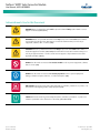
NetSure™ MPPT Solar Converter Module
User Manual, UM1S482000E3
Document Code, 11JG6134DW (Revision B, July 20, 2015)
Specification Number: 1S482000E3
Model Number: S48-2000e3
NetSure™ MPPT Solar Converter Module
User Manual, UM1S482000E3
This page is intentionally blank.
Spec. No: 1S482000E3
Model No: S48-2000e3
Document Code: 11JG6134DW
Revision B, July 20, 2015
NetSure™ MPPT Solar Converter Module
User Manual, UM1S482000E3
Table of Contents
Admonishments Used in this Document ................................................................................................................ ii
Important Safety Instructions .............................................................................................................................. iii
General Safety ........................................................................................................................................................iii
Voltages .................................................................................................................................................................iii
Personal Protective Equipment (PPE).......................................................................................................................iii
Handling Equipment Containing Static Sensitive Components .................................................................................iii
Static Warning ..................................................................................................................................................... iv
Introduction ......................................................................................................................................................... 1
Overview ................................................................................................................................................................ 1
Specifications ......................................................................................................................................................... 1
Operation ............................................................................................................................................................. 7
DC Input Protection Device Requirements/Recommendations ................................................................................ 7
Local Indicators....................................................................................................................................................... 7
Solar Converter High Voltage Shutdown and Lockout Restart .................................................................................. 7
Solar Converter Current Limit .................................................................................................................................. 7
Installing Solar Converters ...................................................................................................................................... 8
Troubleshooting and Repair .................................................................................................................................. 9
Troubleshooting ..................................................................................................................................................... 9
Replacement Procedures ...................................................................................................................................... 10
Spec. No: 1S482000E3
Model No: S48-2000e3
[i]
Document Code: 11JG6134DW
Revision B, July 20, 2015
NetSure™ MPPT Solar Converter Module
User Manual, UM1S482000E3
Admonishments Used in this Document
DANGER! Warns of a hazard the reader will be exposed to that will likely result in death or serious
injury if not avoided. (ANSI, OSHA)
Danger
Warning
Caution
WARNING! Warns of a potential hazard the reader may be exposed to that could result in death or
serious injury if not avoided. This admonition is not used for situations that pose a risk only to
equipment, software, data, or service. (ANSI)
CAUTION! Warns of a potential hazard the reader may be exposed to that could result in minor or
moderate injury if not avoided. (ANSI, OSHA) This admonition is not used for situations that pose a
risk only to equipment, data, or service, even if such use appears to be permitted in some of the
applicable standards. (OSHA)
ALERT! Alerts the reader to an action that must be avoided in order to protect equipment, software,
data, or service. (ISO)
Alert
ALERT! Alerts the reader to an action that must be performed in order to prevent equipment
damage, software corruption, data loss, or service interruption. (ISO)
Alert
FIRE SAFETY! Informs the reader of fire safety information, reminders, precautions, or policies, or of
the locations of fire-fighting and fire-safety equipment. (ISO)
Fire Safety
SAFETY! Informs the reader of general safety information, reminders, precautions, or policies not
related to a particular source of hazard or to fire safety. (ISO, ANSI, OSHA)
Safety
Spec. No: 1S482000E3
Model No: S48-2000e3
[ii]
Document Code: 11JG6134DW
Revision B, July 20, 2015
NetSure™ MPPT Solar Converter Module
User Manual, UM1S482000E3
Important Safety Instructions
General Safety
Danger
DC Output and Battery Voltages
DANGER!
YOU MUST FOLLOW APPROVED SAFETY PROCEDURES.
Danger
Performing the following procedures may expose you to
hazards. These procedures should be performed by
qualified technicians familiar with the hazards
associated with this type of equipment. These hazards
may include shock, energy, and/or burns. To avoid
these hazards:
a) The tasks should be performed in the order
indicated.
b) Remove watches, rings, and other metal objects.
c) Prior to contacting any uninsulated surface or
termination, use a voltmeter to verify that no
voltage or the expected voltage is present. Check
for voltage with both AC and DC voltmeters prior to
making contact.
Personal Protective Equipment (PPE)
Danger
d) Wear eye protection.
Only authorized and properly trained personnel should
be allowed to install, inspect, operate, or maintain the
equipment.
f) For systems operating with 400 VDC power, do not
work on an energized system without full arc flash
and PPE protection.
Do not work on LIVE parts. If required to work or
operate live parts, obtain appropriate Energized Work
Permits as required by the local authority, per NFPA 70E
“Standard for Electrical Safety in the Workplace”.
Voltages
DC Input Voltages
DANGER! This system may operate from 400 VDC input
voltage capable of producing fatal electrical shock. DC
input power must be completely disconnected from the
branch circuits wiring used to provide power to the
system before any DC electrical connections are made.
Follow local lockout/tagout procedures to ensure
upstream branch circuit breakers remain de-energized
during installation. DO NOT apply DC input power to
the system until all electrical connections have been
completed and checked.
Spec. No: 1S482000E3
Model No: S48-2000e3
DANGER! ARC FLASH AND SHOCK HAZARD.
Appropriate PPE and tools required when working on
this equipment. An appropriate flash protection
boundary analysis should be done determine the
“hazard/risk” category, and to select proper PPE.
This product is intended only for installation in a
Restricted Access Location.
e) Use certified and well maintained insulated tools.
Use double insulated tools appropriately rated for
the work to be performed.
Danger
DANGER! This system produces DC Power and may have
a battery source connected to it. Although the DC
voltage is not hazardously high, the solar converters
and/or battery can deliver large amounts of current.
Exercise extreme caution not to inadvertently contact or
have any tool inadvertently contact an output terminal
or battery terminal or exposed wire connected to an
output terminal or battery terminal. NEVER allow a
metal object, such as a tool, to contact more than one
termination or battery terminal at a time, or to
simultaneously contact a termination or battery
terminal and a grounded object. Even a momentary
short circuit can cause sparking, explosion, and injury.
[iii]
Handling Equipment Containing
Static Sensitive Components
Alert
ALERT! Installation or removal of equipment containing
static sensitive components requires careful handling.
Before handling any equipment containing static
sensitive components, read and follow the instructions
contained on the Static Warning Page.
Document Code: 11JG6134DW
Revision B, July 20, 2015
NetSure™ MPPT Solar Converter Module
User Manual, UM1S482000E3
Static Warning
This equipment contains static sensitive components. The warnings listed below must be observed to prevent damage to these
components. Disregarding any of these warnings may result in personal injury or damage to the equipment.
1.
Strictly adhere to the procedures provided in this document.
2.
Before touching any equipment containing static sensitive components, discharge all static electricity from yourself by wearing
a wrist strap grounded through a one megohm resistor. Some wrist straps, such as Emerson Network Power Part Number
631810600, have a built-in one megohm resistor; no external resistor is necessary. Read and follow wrist strap manufacturer’s
instructions outlining use of a specific wrist strap.
3.
Do not touch traces or components on equipment containing static sensitive components.
Handle equipment containing static sensitive components only by the edges that do not have connector pads.
4.
After removing equipment containing static sensitive components, place the equipment only on conductive or anti-static
material such as conductive foam, conductive plastic, or aluminum foil. Do not use ordinary Styrofoam™ or ordinary plastic.
5.
Store and ship equipment containing static sensitive components only in static shielding containers.
6.
If necessary to repair equipment containing static sensitive components, wear an appropriately grounded wrist strap, work on a
conductive surface, use a grounded soldering iron, and use grounded test equipment.
Spec. No: 1S482000E3
Model No: S48-2000e3
[iv]
Document Code: 11JG6134DW
Revision B, July 20, 2015
NetSure™ MPPT Solar Converter Module
User Manual, UM1S482000E3
Introduction
Figure 1. Output Voltage vs. Output Current
Output Voltage vs. Output Current at Max. Power
Overview
•
Constant Voltage Mode: For any initial output voltage
setting from 42 VDC to 58 VDC, output voltage remains
constant regardless of load. This is the normal operating
condition, in which loads are being supplied and batteries
are float charged. Solar converters operate in the
Constant Voltage Mode unless load increases to the point
where the product of load current and output voltage is
approximately 2000 W.
•
Constant Power Mode: As load increases above
approximately 2000 W (non-adjustable), output current
continues to increase, but output voltage decreases as
required to maintain constant output power. Solar
converters operate in the Constant Power Mode unless
load continues to increase to the point where the current
limit setting is reached.
•
Constant Current Mode: If load increases to the current
limit setting, output voltage decreases linearly to
maintain output current at the current limit setting.
Output Voltage (V)
60
40
30
20
10
0
•
5
10
15 20 25 30
Output Current (A)
35
40
45
Power Derating Based on Input Voltage: The solar
converter power varies with changes in input voltage and
output voltage. It uses an advanced power limitation
method. The lower input threshold is 200 VDC. The solar
converter can provide its maximum rated power (2000
W) as long as the input voltage is within the range of 200
VDC to 420 VDC. Below 200 VDC, and down to 120 VDC,
the solar converter will continue to operate normally but
will be in a power derating mode. The relationship
between the output power and input voltage is
illustrated in Figure 2.
Figure 2. Power Derating Based on Input Voltage
Output Power vs. Input Voltage and Vo > 48 V
at Temp ≤55 ℃
120.0%
100.0%
80.0%
60.0%
40.0%
20.0%
0.0%
0
Specifications
•
DC Output Ratings
NOTE: A current limitation can be set by the User and the
output voltage level is set through the controller.
•
Voltage: Nominal -48 VDC, positive ground. Output
voltage is adjustable from -42 VDC to -58 VDC via the
associated controller.
•
Output Power and Current: 2000 W (41.7 A) @ 200 VDC
to 420 VDC input and -48 VDC output.
•
Output Characteristics: Refer to Figure 1 for a graph of
output voltage vs. output current.
Spec. No: 1S482000E3
Model No: S48-2000e3
50
0
% of Output Power
The MPPT Solar Converter provides load power, battery float
current, and battery recharge current during normal operating
conditions. The solar converter is a constant power design. The
solar converter is rated at its maximum output power. This means
that, within the normal operating ambient temperature range and
input voltage range, the maximum available output power is a
constant 2000 W. Within these ranges, the solar converter
operates in one of three modes, depending upon load demands.
Transition between modes is completely automatic. If ambient
temperature rises above or input voltage falls below acceptable
values, the solar converter continues to operate but at derated
output power levels.
[1]
50 100 150 200 250 300 350 400 450
Input Voltage (VAC)
Power Derating Based on Temperature: The solar
converter delivers full power when operating at an
ambient temperature of +55 °C (+131 °F) or below. Each
solar converter continuously monitors the ambient
temperature surrounding the power conversion circuit. If
this temperature for any reason (such as a high ambient
temperature) increases above approximately +55 °C
(+131 °F), the solar converter will not shut down. Rather,
the solar converter limits its maximum output power to
maintain the temperature of the power conversion circuit
within design parameters. Operation between +55 °C
(+131 °C) and +80 °C (+176 °F) will result in output power
being decreased. Full power capability is restored when
the temperature decreases to below approximately
Document Code: 11JG6134DW
Revision B, July 20, 2015
NetSure™ MPPT Solar Converter Module
User Manual, UM1S482000E3
voltage, and input frequency at a constant ambient
temperature. The associated system controller may
provide increased regulation.
+55 °C (+131 °F). Refer to Figure 3 to view the
relationship between the output power and the ambient
temperature.
b.
WARNING! The module is rated for continuous
operation at full output power up to +55 °C (+131 °F).
Operation between +55 °C (+131 °F) and +80 °C
(+176 °F) will result in output power decrease.
Operation above +80 °C (+176 °F) is considered
abnormal and should be used on a temporary1 basis
only.
Warning
1
•
Temporary Operation at Abnormal Temperature:
Temporary operation is defined as a period of not
more than eight consecutive hours per day, and a
total of not more than 15 days in a year. (This refers
to a total of 120 hours in any given year, but no
more than 15 occurrences in that one-year period.)
Filtering:
a.
Other power rating values are as follows (refer to Figure
3):
a.
At an ambient temperature of +65 °C (+149 °F),
the power delivered by the solar converter is
1800 W.
b.
At an ambient temperature of +70 °C (+158 °F),
the power delivered by the solar converter is
1500 W.
Dynamic: For any step load change within the range
of 10 % to 90 % of full load within 50 microseconds,
per Telcordia GR-947-CORE, the maximum voltage
transient will not exceed 5 % of the initial steady
state voltage within 50±10 microseconds. Recovery
to within 1 % of the initial steady state voltage does
not exceed 1 milliseconds.
b.
Voice Band Noise: Complies with Telcordia
GR-947-CORE.
1.
Output noise according to Telcordia
GR-947-CORE is <38 dBrnC typical at normal
input and 30 % to 80 % of rated load for more
than one solar converter.
2.
Psophometric noise is ≤ 2 mV typical at 30 % to
80 % of rated load for more than one solar
converter.
Wide Band Noise: Complies with Telcordia
GR-947-CORE.
1.
Figure 3. Power Derating Based on Temperature
Output Power vs. Temperature @ Vin ≥ 200 VDC
120
DC Input Ratings
% of Output Power
100
80
•
60
Nominal Input Voltage: 140 VDC to 400 VDC.
Operating Range: 120 VDC to 420 VDC.
40
20
•
Inrush Current: Peak does not exceed 1.5 times of the
peak value of the maximum steady-state input current at
25 °C, and shall not trigger the unit's internal input fault
protection device(s). Charging of input X and Y filter
capacitors shall be ignored.
•
Typical Input Data:
0
-40
-20
0
20
40
Temperature (℃)
60
80
100
NOTE:
Green Line: at 200 VDC < Vin < 250 VDC and
50 VDC < Vout < 56 VDC.
Blue Line: at 200 VDC < Vin < 420 VDC and
48 VDC < Vout < 58 VDC, exclude Region 1.
•
Wideband noise emission is <250 mV peak to
peak between 0 Hz to 100 MHz, and <50 mV
rms in any 3 kHz band 10 KHz to 20 MHz.
Regulation:
a.
a.
Refer to Table 1.
b.
Maximum Input Current: 12 A.
c.
Efficiency Curve: Refer to Figure 4.
Static: Steady state regulation is ±0.6 % as
controlled within the solar converter for any and all
combinations of load from no load to full load, input
Spec. No: 1S482000E3
Model No: S48-2000e3
[2]
Document Code: 11JG6134DW
Revision B, July 20, 2015
NetSure™ MPPT Solar Converter Module
User Manual, UM1S482000E3
Table 1.
Typical Input Data
Nominal Input Voltage
260 VDC
300 VDC
380 VDC
Spec. No: 1S482000E3
Model No: S48-2000e3
Input Power (W)
Output Voltage (V)
Output Current (A)
Efficiency
2124.3
53.474
37.856
95.29%
1952.4
53.490
34.844
95.46%
1780.5
53.498
31.828
95.63%
1663.9
53.510
29.771
95.74%
1493.8
53.524
26.754
95.86%
1271.8
53.550
22.792
95.97%
1104.1
53.561
19.784
95.97%
945.7
53.584
16.927
95.91%
779.1
53.600
13.915
95.73%
612.3
53.616
10.897
95.42%
424.3
53.570
7.490
94.57%
223.3
53.610
3.740
89.79%
133.8
53.640
1.875
75.17%
2114.8
53.450
37.790
95.51%
1943.3
53.460
34.780
95.68%
1772.6
53.470
31.760
95.80%
1566.7
53.490
28.125
96.02%
1433.3
53.490
25.746
96.08%
1265.3
53.510
22.740
96.17%
1098.3
53.530
19.730
96.16%
1045.1
53.530
18.780
96.19%
826.6
53.550
14.820
96.01%
625.9
53.570
11.174
95.64%
426.2
53.580
7.530
94.66%
224.5
53.630
3.724
88.96%
133.6
53.650
1.822
73.17%
2094.4
53.450
37.560
95.85%
1893.7
53.470
34.020
96.06%
1671.4
53.480
30.075
96.23%
1563.1
53.490
28.150
96.33%
1386.1
53.500
24.980
96.42%
1223.5
53.510
22.060
96.48%
1110.0
53.520
20.010
96.48%
1042.0
53.530
18.775
96.45%
890.8
53.550
16.030
96.36%
723.2
53.560
12.970
96.06%
626.1
53.570
11.200
95.83%
425.8
53.580
7.530
94.75%
224.8
53.630
3.750
89.46%
[3]
Document Code: 11JG6134DW
Revision B, July 20, 2015
NetSure™ MPPT Solar Converter Module
User Manual, UM1S482000E3
Figure 4. Efficiency Curve
solar converter does not exceed the Operating Ambient
Temperature Range stated above.
Environmental Ratings
•
Operating Ambient Temperature Range:
•
-40 °C (-40 °F) to +55 °C (+131 °F) with full power
performance.
Single Solar Converter Audible Noise: At 25 °C ≤50 dB(A)
with fan in high speed. Measurement made at 0.6 m
distance in front of solar converter and at same
horizontal line of the middle of solar converter.
•
High Voltage Category: II
•
Temperature Coefficient: 0.02 % per degrees Celsius.
•
Power Distribution System: TN/TT/IT
•
Storage Ambient Temperature Range: -40 °C (-40 °F) to
+70 °C (+158 °F).
•
Relative Humidity: This solar converter is capable of
operating in an ambient relative humidity range of 0 % to
95 %, non-condensing.
•
Altitude: 2000 m (6560 ft) at full power (power limited
for heights above 2000 m).
•
Surge Protection: Compliance with EN61000-4-5 (4 kV
Line to Line, 4 kV Line to Earth). Capable of withstanding
surges per ANSI/IEEE C 62.41 1999 Category B3 across
the input terminals.
a.
Solar converters operating in an approved solar
converter mounting shelf conform to the
requirements of FCC rules Part 15, Class B for
Radiated and Class A for Conducted emissions limits.
NOTE: This level of protection is a widely used standard
for telecommunications power equipment. As with all
such equipment, it is the end user's responsibility to
provide an adequately sized Surge Suppression Device at
the commercial power service entrance of the building
that reduces all incoming surges to levels below the
classes/categories stated for the equipment.
b.
Solar converters operating in an approved solar
converter mounting shelf conform to the
requirements of European Norm, EN55022, Class B
for Radiated and Class A for Conducted emissions
limits.
•
a.
+55 °C (+131 °F) to +80 °C (+176 °F) with derating
output.
b.
NOTE: The solar converter module is recommended to
be used in an environment with Pollution of Degree 2 or
less. Pollution Degree 2 applies where there is only nonconductive pollution that might temporarily become
conductive due to occasional condensation (such as the
office environment).
•
Compliance Information
Ventilation Requirements: The solar converters are fan
cooled and utilize front to back forced ventilation. A
solar converter must be mounted so ventilating openings
are not blocked and temperature of the air entering the
Spec. No: 1S482000E3
Model No: S48-2000e3
EMI/RFI Suppression:
[4]
•
EMC: ETSI EN 300 386, FCC CFR 47 Part 15 class B,
Telcordia GR-1089-CORE.
•
EMI Load Range: 10 % to 100 %.
Document Code: 11JG6134DW
Revision B, July 20, 2015
NetSure™ MPPT Solar Converter Module
User Manual, UM1S482000E3
•
Safety: IEC 60950, EN 60950, UL 60950.
•
GR-3108 Class 2 Compliant
•
Output Protection:
a.
Overload / Reverse Current: The solar converter has
a 63 A fuse in the negative output DC bus. This fuse
is not customer replaceable. The solar converter can
be plugged into or pulled out of a shelf while
operating, without damage or opening the fuse.
b.
Current Limiting: The solar converter has a current
limit function. The current limit point can be set
between the range of 0 A to 41.7 A, adjustable via
the controller. The current limit accuracy is ±1.5 A
when the output voltage ranges from 42 V to 58 V.
c.
Advanced Current Limit Function: The solar
converter has an advanced Current Limit Function.
When a short circuit occurs at the solar converter
output terminals, the solar converter will keep its
output current at a constant value (value that is
configurable via the controller). This function
effectively protects the solar converter and the
equipment connected to the solar converter. When
the short circuit fault is cleared, the solar converter
will automatically restore back to normal operation.
d.
High Voltage Shutdown:
Standard Features
•
Type of Power Conversion Circuit: High frequency.
•
Constant Voltage Mode: For any initial output voltage
setting from 42 to 58 volts, output voltage remains
constant regardless of load. This is the normal operating
condition, in which loads are being supplied and batteries
are float charged. Solar converters operate in the
Constant Voltage Mode unless load increases to the point
where the product of load current and output voltage is
approximately 2000 W.
•
Constant Power Mode: As load increases above
approximately 2000 W (non-adjustable), output current
continues to increase, but output voltage decreases as
required to maintain constant output power. Solar
converters operate in the Constant Power Mode unless
load continues to increase to the point where the current
limit setting is reached.
•
Constant Current Mode: If load increases to the current
limit setting, output voltage decreases linearly to
maintain output current at the current limit setting.
•
1.
Software settable HVSD level (from controller)
56 V to 59 V. The software restart hysteresis is
0.5 V, ±0.2 V.
2.
Back-up hardware HVSD (High Voltage Shut
Down) at 59.5 V, ±0.5 V.
3.
In the case of a second HVSD within 5 minutes
(time value configurable via the controller) the
unit shall require to be manually restarted.
Method of manual restart: Reset the solar
converter through the controller or remove the
solar converter from the system and then reinstall the solar converter into the system.
Input Protection:
a.
b.
Input Over/Under Voltage Protection: The solar
converter will shut down at low or high voltage
input; based on the following voltage levels:
1.
Low Voltage Disable Point: 115 V, ±5 V;
hysteresis is 10 VDC for restart.
2.
High Voltage Disable Point: 425 V, ±5 V;
hysteresis is 10 VDC for restart.
Between 120 V and 200 V the output power will be
derated linearly based on the input voltage as
follows:
1.
At input voltage of 120 V with output >48 V,
maximum output power is 1200 W.
2.
At input voltage of 154 V with output >48 V,
maximum output power is 1540 W.
3.
At input voltage of 176 V with output >48 V,
maximum output power is 1760 W.
4.
At input voltage of 200 V and output >48 V,
maximum output power is 2000 W.
Spec. No: 1S482000E3
Model No: S48-2000e3
[5]
•
Over-Temperature Protection: The solar converter
provides over temperature protection by derating output
power and recovers automatically.
•
Active Load Sharing: The solar converter uses advanced
digital active load sharing technology that maintains
balancing to within 3 % of rated current.
•
Hot Swappable: The solar converter is designed to be
plug-and-play. The solar converter can be inserted or
removed from a live DC power system with no damage.
When the solar converter is plugged into the system, the
system output voltage will not be affected.
Document Code: 11JG6134DW
Revision B, July 20, 2015
NetSure™ MPPT Solar Converter Module
User Manual, UM1S482000E3
•
Cooling: Each solar converter module contains a fan for
front-to-back force air-cooling.
Table 2.
a.
Fan Fault Protection: The solar converter module
shuts down and its alarm indicator (red) flashes if the
fan fails. Fan failure is detected and reported to
controller.
Commands / signals that can
be received by the solar
converter module from the
controller.
b.
Fan Control: Fan speed is continuously variable.
When input voltage is within normal range, the builtin processor adjusts fan speed according to the solar
converter module’s internal temperature and output
power. For example, a higher temperature or
output power increases the fan speed. This feature
can be disabled via the controller, allowing the fan to
run at full speed regardless of temperature.
• Turn On/Off
• Current Walk-in On/Off
• HVSD (High Voltage
Shutdown) Reset
• Current Limit Adjustment
• Voltage Regulation
•
Paralleling: Up to 30 solar converters can be connected
in parallel in one system.
•
Communication Failure: The solar converter’s protection
indicator (yellow) will flash should it experience a
communication failure. The failure information will be
reported to the controller and the controller will process
the failure accordingly. During a communication failure,
in order to protect the battery, the solar converter output
voltage will automatically be adjusted as follows. When
used with the SCU+ Controller, solar converter output
voltage goes to a default value (53.5 V, which can be
modified using the SCU+ Controller). When used with
the ACU+ or NCU Controller, solar converter output
voltage goes to the controller’s float voltage setting (this
setting is stored in the solar converter). The solar
converter will revert to normal operation once normal
communication is restored.
•
•
Information gathered by the
controller from the solar
converter module.
•
•
•
•
•
•
•
•
•
•
•
•
•
•
•
•
Input Voltage
Output Voltage
Output Current
Current Limit Setting
Temperature
Over Voltage Setting
On/Off Status
Fault Alarms, such as:
HVSD
Fan Fail
Protection Alarms, such as:
Input Voltage Protection
Inner DC Bus Voltage
Protection
High Temperature Protection
Thermal Derating
Imbalance Output Current
Address
Code
Date
Software Version
Hardware Version
Mechanical Specifications
•
Solar Converter Output Current Imbalance: When load
sharing severe imbalance (output fuse open) and the
output current drops to zero in average current >10%
system, then the red fault indicator will illuminate.
Monitoring Function: The solar converter has a built-in
advanced DSP that monitors and controls the operation
of the solar converter. The DSP also communicates with
the controller in real time through the CAN bus. Table 2
lists the different commands and information exchanged
between the solar converter and the controller.
Spec. No: 1S482000E3
Model No: S48-2000e3
Exchange of Information between Solar Converter and
Controller
[6]
Dimensions:
a.
Millimeters: 41.0 (Height) X 84.5 (Width) X 252.5
(Depth)
b.
Inches: 1.6 (Height) X 3.3 (Width) X 9.9 (Depth)
•
Weight: 1.13 kg (2.49 lbs)
•
Indicators:
a.
Power (Green LED)
b.
Protection (Yellow LED)
c.
Alarm (Red LED)
Document Code: 11JG6134DW
Revision B, July 20, 2015
NetSure™ MPPT Solar Converter Module
User Manual, UM1S482000E3
Solar Converter High Voltage Shutdown and Lockout
Restart
Operation
DC Input Protection Device
Requirements/Recommendations
Procedure
1.
Refer to the system documentation supplied with the system the
solar converter is installed in.
Local Indicators
Location and Identification: Refer to Figure 5.
Solar Converter Current Limit
Description: There are three (3) indicators located on the solar
converter’s front panel. The functions of these indicators are as
shown in Table 3.
NOTE: DC voltage must be present at the solar converter
output terminals (from battery or an operating solar
converter) or DC voltage at the input terminals.
Figure 5. Local Indicator Locations
Power Indicator (Green)
Protection Indicator (Yellow)
Alarm Indicator (Red)
Spec. No: 1S482000E3
Model No: S48-2000e3
Remove the solar converter, wait 30 seconds or more
(until the LEDs on the solar converter extinguish), then
re-insert the solar converter.
[7]
When setting total solar converter current limit, the set point to
each solar converter is the total set point divided by the number of
solar converters. For example, if the system contains five solar
converters and the current limit is set to 150 amps then each solar
converter has a current limit set point of 30 amps. If one or more
solar converters are removed or fail it will take several seconds for
the individual set points to the remaining solar converters to be
reset. In the example given, if one solar converter is removed the
current limit set point will drop to 120 amps (30 amps times four
remaining solar converters) until the controller can send updated
set points to the remaining solar converters. This takes a couple
communication cycles (several seconds) after which each solar
converter would have a new set point of 37.5 amps for a total of
150 amps. The total current limit of the solar converters should
not be set such that the loss of the redundant solar converters will
cause this temporary set point to drop below the actual maximum
expected load. If batteries are used on the solar converter output,
the batteries should support the load until the current limit set
points can be re-established due to loss of a solar converter.
Document Code: 11JG6134DW
Revision B, July 20, 2015
NetSure™ MPPT Solar Converter Module
User Manual, UM1S482000E3
Table 3.
Solar Converter Module Indicators
Indicator
Power
(Green)
Normal State
Alarm State
Alarm Cause
No input voltage.
Internal input fuse open.
Off
On
The solar converter is being
identified by the controller.
Flashing
DC input under/over voltage.
PFC over voltage.
Moderate load sharing imbalance.
Solar converter not inserted into the
slot completely.
Solar converter over-temperature
protection.
On
Protection
(Yellow)
Alarm
(Red)
Off
Flashing
Loss of communication with the
controller (the solar converter can
provide power).
On
Severe load sharing imbalance.
Solar converter output disabled for
any reason, including overvoltage
shutdown and internal output fuse
open.
Solar converter addresses
contradictory.
Flashing
Fan not operating (solar converter
shuts down).
Off
Installing Solar Converters
Procedure
Solar converter modules can be inserted or removed with power
applied (hot swappable).
NOTE: Refer to Figure 6 as this procedure is performed.
NOTE: Each solar converter module locks into a module
mounting shelf by means of a latch located on the
bottom of the module. The latch and solar converter
module handle are interactive. Pushing the handle up
into the module’s front panel causes the latch to extend
to the locking position; pulling the handle down out from
the module’s front panel causes the latch to retract. See
Figure 6.
Caution
Warning
CAUTION! This solar converter module contains double
pole fusing; parts of the equipment that remain
energized might represent a hazard during servicing
after operation of the fuse.
WARNING! To prevent damage to the latching
mechanism, ensure the handle is in the open position
when installing or removing a solar converter module.
NEVER hold the handle in the closed position when
installing a solar converter module into a shelf.
Spec. No: 1S482000E3
Model No: S48-2000e3
[8]
1.
Unpack the module.
2.
Place the module into an unoccupied mounting slot
without sliding it in completely.
3.
Loosen the captive screw on the module’s handle. Pull
the handle down out from the module’s front panel (this
will also retract the latch mechanism). See Figure 6.
4.
Push the module completely into the shelf.
5.
Push the handle up into the module’s front panel. This
will lock the module securely to the shelf. Tighten the
captive screw on the handle.
6.
Repeat the above steps for each solar converter module
being installed in the system.
7.
After the solar converter modules are physically installed
in the mounting shelf(s), they are ready for operation
immediately after power is supplied to them.
Document Code: 11JG6134DW
Revision B, July 20, 2015
NetSure™ MPPT Solar Converter Module
User Manual, UM1S482000E3
8.
Certain functions (i.e. solar converter current limit, solar
converter addressing) may require adjustment when
adding or replacing a solar converter module. Refer to
“Solar Converter Current Limit” on page 7 and the Power
System documentation for instructions.
Troubleshooting and Repair
Troubleshooting
Solar Converter Current Sharing Imbalance
When multiple solar converters are operating in parallel and the
load is greater than 10 %, if the current sharing imbalance among
them is greater than 3 %, check if the solar converter is properly
seated in the shelf.
Figure 6. Installing Solar Converter Module
If the current sharing imbalance still persists following the
verification suggested above, replace the solar converter
exhibiting the current imbalance.
Solar Converter Fault Symptoms and Troubleshooting
Captive Screw
The fault indicators that can be displayed by the solar converter are
as follows. Refer to Table 4 for a list of possible causes and
corrective actions.
Handle
•
Power Indicator (Green) Off
•
Protection Indicator (Yellow) ON
•
Protection Indicator (Yellow) Flashing
•
Alarm Indicator (Red) ON
•
Alarm Indicator (Red) Flashing
Latch
Spec. No: 1S482000E3
Model No: S48-2000e3
[9]
Document Code: 11JG6134DW
Revision B, July 20, 2015
NetSure™ MPPT Solar Converter Module
User Manual, UM1S482000E3
Table 4.
Solar Converter Troubleshooting
Symptom
Power Indicator
(Green) Off
Protection
Indicator
(Yellow) On
Protection
Indicator
(Yellow)
Flashing
Alarm
Indicator
(Red) On
Alarm Indicator
(Red) Flashing
Possible Cause(s)
Suggested Action(s)
No input voltage.
Make sure there is input voltage.
Internal input fuse open.
Replace the solar converter.
DC input under/over
voltage.
Correct the DC input voltage to within the acceptable
range.
PFC over voltage.
Replace the solar converter.
Moderate load sharing
imbalance.
Check if the solar converter is properly seated in the
shelf. If this does not correct the fault, replace the solar
converter.
Solar converter not
inserted into the slot
completely.
Remove and properly insert the solar converter.
Solar converter overtemperature protection.
Fan rotor blocked: remove any object that may be
blocking the fan.
Ventilation blocked (inlet or outlet): remove any object
that may be blocking the inlet or outlet.
Ambient temperature too high or solar converter inlet
too close to a heat source: lower the ambient
temperature or relocate the heat source.
Loss of communication
with controller (the solar
converter can provide
power).
Check the communication cables.
Remove and properly insert the solar converter and
controller.
Severe load sharing
imbalance.
Solar converter output
disabled for any reason,
including overvoltage
shutdown and internal
output fuse open.
Remove the solar converter from its shelf and then
reinstall after 30 seconds. If solar converter fails to start
or shuts down again; replace the solar converter.
Solar converter addresses
contradictory.
Replace the solar converter.
Fan not operating (solar
converter shuts down).
Replace the fan.
Replacement Procedures
NOTE: Each solar converter module locks into a module
mounting shelf by means of a latch located on the
bottom of the module. The latch and solar converter
module handle are interactive. Pushing the handle up
into the module’s front panel causes the latch to extend
to the locking position; pulling the handle down out from
the module’s front panel causes the latch to retract. See
Figure 6.
Solar Converter Module Replacement
Solar converter modules can be inserted or removed with power
applied (hot swappable).
Spec. No: 1S482000E3
Model No: S48-2000e3
[10]
Document Code: 11JG6134DW
Revision B, July 20, 2015
NetSure™ MPPT Solar Converter Module
User Manual, UM1S482000E3
Danger
Warning
DANGER! Take care when removing a solar converter
module that was in operation, as solar converter module
surfaces could be very hot.
WARNING! To prevent damage to the latching
mechanism, ensure the handle is in the open position
when installing or removing a solar converter module.
NEVER hold the handle in the closed position when
installing a solar converter module into a shelf.
Solar Converter Fan Replacement
Each solar converter uses a fan (P/N: 32010474) for cooling. If fan
replacement should become necessary, perform the following
procedure.
Refer to Figure 7 as this procedure is performed.
Warning
Procedure
NOTE: Refer to Figure 6 as this procedure is performed.
1.
Performing this procedure may activate external alarms.
Do one of the following. If possible, disable these alarms.
If these alarms cannot be easily disabled, notify the
appropriate personnel to disregard any alarms associated
with this system while this procedure is performed.
WARNING! In a system with NO redundant solar
converter, battery must have sufficient reserve to power
the load(s) while the solar converter is removed for fan
replacement.
NOTE: When performing any step in this procedure that
requires removal of existing hardware, retain all hardware
for use in subsequent steps.
Procedure
1.
Performing this procedure may activate external alarms.
Do one of the following. If possible, disable these alarms.
If these alarms cannot be easily disabled, notify the
appropriate personnel to disregard any alarms associated
with this system while this procedure is performed.
2.
Loosen the captive screw on the module’s handle. Pull
the handle down out from the module’s front panel (this
will also retract the latch mechanism). See Figure 6.
3.
Grasp the handle and pull firmly to remove the module
from the shelf.
2.
Remove the solar converter from the shelf. Refer to a
previous procedure for step-by-step instructions.
4.
Place the replacement solar converter module into the
mounting position without sliding it in completely.
3.
5.
Loosen the captive screw on the module’s handle. Pull
the handle down out from the module’s front panel (this
will also retract the latch mechanism). See Figure 6.
Place the solar converter on a static-safe work surface.
Connect an approved grounding strap to your wrist for
the remainder of this procedure.
4.
6.
Push the module completely into the shelf.
On this solar converter; remove the front panel by
removing the three (3) screws securing the front panel to
the chassis.
7.
Push the handle up into the module’s front panel. This
will lock the module securely to the shelf. Tighten the
captive screw on the handle.
5.
For proper orientation of the new fan, observe the
location of the fan wires and the fan rotation and air flow
arrows on the old fan.
8.
Certain functions (i.e. solar converter current limit, solar
converter addressing) may require adjustment when
adding or replacing a solar converter module. Refer to
“Solar Converter Current Limit” on page 7 and the Power
System documentation for instructions.
6.
Carefully remove the fan from the solar converter chassis
and unplug the fan power cable from the printed circuit
card.
7.
Plug the power cable of the replacement fan into the
connector on the printed circuit card. Carefully slide the
replacement fan into the solar converter chassis (ensure
the fan wires and fan rotation and air flow arrows match
the orientation of the old fan).
8.
Note that the fan has four holes in the front corners and
that the faceplate has three tabs. Carefully slide the
faceplate into position, aligning the fan holes with the
faceplate tabs. Secure the faceplate to the solar
converter chassis with the three (3) screws previously
removed.
9.
After the solar converter modules are physically installed
in the mounting shelf(s), they are ready for operation
immediately after power is supplied to them. Verify that
the solar converters are operating normally.
10. Enable the external alarms, or notify appropriate
personnel that this procedure is finished.
11. Ensure that there are no local or remote alarms active on
the system.
Spec. No: 1S482000E3
Model No: S48-2000e3
[11]
Document Code: 11JG6134DW
Revision B, July 20, 2015
NetSure™ MPPT Solar Converter Module
User Manual, UM1S482000E3
9.
Replace the solar converter into the shelf. Refer to the
previous procedure for step-by-step instructions.
Figure 7. Fan Replacement
10. When the fan starts, check to ensure that it is providing
front-to-back airflow. If air direction is wrong,
immediately remove the solar converter from the shelf.
Repeat previous steps to check fan orientation, and
correct as necessary. Reinstall the solar converter and
again check for proper airflow.
11. Enable the external alarms, or notify appropriate
personnel that this procedure is finished.
12. Ensure that there are no local or remote alarms active on
the system.
Align holes in fan with
tabs on faceplate.
Fan
S48-20
00e3
Faceplate Mounting
Screws (3)
Faceplate
Spec. No: 1S482000E3
Model No: S48-2000e3
[12]
Document Code: 11JG6134DW
Revision B, July 20, 2015
NetSure™ MPPT Solar Converter Module
User Manual, UM1S482000E3
This page is intentionally blank.
Spec. No: 1S482000E3
Model No: S48-2000e3
[13]
Document Code: 11JG6134DW
Revision B, July 20, 2015
NetSure™ MPPT Solar Converter Module
User Manual, UM1S482000E3
The information contained in this document is subject to change without notice and may
not be suitable for all applications. While every precaution has been taken to ensure the
accuracy and completeness of this document, Emerson Network Power, Energy Systems,
North America, Inc. assumes no responsibility and disclaims all liability for damages resulting from use of this information or for any errors or omissions. Refer to other local
practices or building codes as applicable for the correct methods, tools, and materials to
be used in performing procedures not specifically described in this document.
The products covered by this instruction manual are manufactured and/or sold by Emerson
Network Power, Energy Systems, North America, Inc. This document is the property of
Emerson Network Power, Energy Systems, North America, Inc. and contains confidential and
proprietary information owned by Emerson Network Power, Energy Systems, North
America, Inc. Any copying, use or disclosure of it without the written permission of Emerson
Network Power, Energy Systems, North America, Inc. is strictly prohibited.
Names of companies and products are trademarks or registered trademarks of the
respective companies. Any questions regarding usage of trademark names should be
directed to the original manufacturer.
EmersonNetworkPower.com/Energy Systems (North America )
EmersonNetworkPower.eu/EnergySystems (EMEA)
© Emerson Network Power, Energy Systems, North America, Inc. 2015.
Business-C ritical Continui ty ™, Emerson Network Powe r™, the Emerson Netw ork Power logo , Emer son™ and Conside r it Solved are serv ice marks and
trademar ks of Emer son Electric Co. EnergyMaster ™, eSure™, NetPer form™, NetR each ™, NetSpan™, NetSure™ and NetXtend ™ are tradema rks of Eme rson
Network Power, Energy Syste ms, Nor th America, Inc . Any other product, brand, or company names or logos are the property of the respective owner.
Spec. No: 1S482000E3
Model No: S48-2000e3
While every precaution has been taken to ensure accuracy and
completeness herein, Emerson Electric Co. assumes no responsibility,
and disclaims all liability, for damages resulting from use of this
information or for any errors or omissions. Specifications subject to
change without notice.
Document Code: 11JG6134DW
Revision B, July 20, 2015