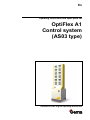
1
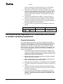
En
Operating instructions and spare parts list
OptiFlex A1
Control system
(AS03 type)
Translation of the original operating instructions
V 08/13
Documentation OptiFlex A1 Control system
© Copyright 2006 Gema GmbH
All rights reserved.
This publication is protected by copyright. Unauthorized copying is prohibited by law. No part of this publication may be reproduced, photocopied, translated, stored on a retrieval system or transmitted in any form or
by any means for any purpose, neither as a whole nor partially, without
the express written consent of Gema GmbH.
OptiTronic, OptiGun, EasyTronic, EasySelect, OptiFlow and SuperCorona are registered trademarks of Gema GmbH.
OptiMatic, OptiMove, OptiMaster, OptiPlus, MultiTronic and Gematic are
trademarks of Gema GmbH.
All other product names are trademarks or registered trademarks of their
respective holders.
Reference is made in this manual to different trademarks or registered
trademarks. Such references do not mean that the manufacturers concerned approve of or are bound in any form by this manual. We have endeavored to retain the preferred spelling of the trademarks, and registered trademarks of the copyright holders.
To the best of our knowledge and belief, the information contained in this
publication was correct and valid on the date of issue. Gema GmbH
makes no representations or warranties with respect to the contents or
use of this publication, and reserves the right to revise this publication
and make changes to its content without prior notice.
Printed in Switzerland
Gema GmbH
Mövenstrasse 17
9015 St. Gallen
Switzerland
Phone: +41-71-313 83 00
Fax.: +41-71-313 83 83
E-Mail: [email protected]
Homepage: www.gemapowdercoating.com
V 08/13
Table of contents
General safety regulations
3
Safety symbols (pictograms)................................................................................... 3
Conformity of use .................................................................................................... 3
Technical safety regulations for stationary electrostatic powder spraying
equipment ............................................................................................................... 4
General information ................................................................................... 4
Safety conscious working .......................................................................... 5
Individual safety regulations for the operating firm and/or operating
personnel ................................................................................................... 5
Notes on special types of hazard ............................................................... 6
Safety requirements for electrostatic powder coating ................................ 7
A summary of the rules and regulations .................................................... 8
Product specific security measures ...................................................................... 10
About this manual
11
General information .............................................................................................. 11
Function description
13
Field of application ................................................................................................ 13
Scope of delivery .................................................................................................. 13
OptiFlex A1 Control system - components ........................................................... 14
OptiFlex A1 Control system - possible configurations .......................................... 15
Automatic equipment without reciprocator............................................... 15
Automatic equipment with reciprocator.................................................... 15
Technical data
17
OptiFlex A1 Control system .................................................................................. 17
Electrical data .......................................................................................... 17
Pneumatical data ..................................................................................... 17
Dimensions .............................................................................................. 17
Start-up
19
Setting up and mounting ....................................................................................... 19
Assembly notes ........................................................................................ 19
OptiFlex A1 - control cabinet.................................................................... 20
Procedure for initial start up .................................................................................. 20
General information ................................................................................. 20
Mains connection ..................................................................................... 20
Compressed air ........................................................................................ 21
Schematic diagrams
23
OptiFlex A1 Control system - pneumatical diagram ............................................. 23
OptiFlex A1 Control system - interlocking diagram............................................... 24
OptiFlex A1 Control system
Table of contents • 1
V 08/13
Spare parts list
25
Ordering spare parts............................................................................................. 25
OptiFlex A1 control cabinet - spare parts list........................................................ 26
OptiFlex A1 control cabinet - spare parts list........................................................ 27
OptiFlex A1 - mounting plate ................................................................................ 28
OptiFlex A1 - mounting plate ................................................................................ 29
2 • Table of contents
OptiFlex A1 Control system
V 08/13
General safety regulations
This chapter sets out the fundamental safety regulations that must be followed by the user and third parties using the OptiFlex A1 Control system.
These safety regulations must be read and understood before the
OptiFlex A1 Control system is used.
Safety symbols (pictograms)
The following warnings with their meanings can be found in the Gema
operating instructions. The general safety precautions must also be followed as well as the regulations in the operating instructions.
DANGER!
Danger due to live electricity or moving parts. Possible consequences:
Death or serious injury
WARNING!
Improper use of the equipment could damage the machine or cause it to
malfunction. Possible consequences: minor injuries or damage to equipment
INFORMATION!
Useful tips and other information
Conformity of use
1. The OptiFlex A1 Control system is built to the latest specification
and conforms to the recognized technical safety regulations. It is
designed for the normal application of powder coating.
2. Any other use is considered as non-conform. The manufacturer
is not responsible for damage resulting from improper use of this
equipment; the end-user alone is responsible. If the OptiFlex A1
Control system is to be used for other purposes or other substances outside of our guidelines then Gema GmbH should be
consulted.
3. Observance of the operating, service and maintenance instructions specified by the manufacturer is also part of conformity of
use. The OptiFlex A1 Control system should only be used, main-
OptiFlex A1 Control system
General safety regulations • 3
V 08/13
tained and started up by trained personnel, who are informed
about and are familiar with the possible hazards involved.
4. Start-up (i.e. the execution of a particular operation) is forbidden
until it has been established that the OptiFlex A1 Control system
has been set up and wired according to the guidelines for machinery (2006/42 EG). EN 60204-1 (machine safety) must also
be observed.
5. Unauthorized modifications to OptiFlex A1 Control system exempt the manufacturer from any liability from resulting damage.
6. The relevant accident prevention regulations, as well as other
generally recognized safety regulations, occupational health and
structural regulations are to be observed.
7. Furthermore the country-specific safety regulations must be observed.
Explosion protection
II 2 D
Protection type
Temperature class
IP54
T6 (zone 21)
T4 (zone 22)
Technical safety regulations for stationary electrostatic powder spraying equipment
General information
The powder spraying equipment from Gema is designed with safety in
mind and is built according to the latest technological specifications. This
equipment can be dangerous if it is not used for its specified purpose.
Consequently it should be noted that there exists a danger to life and
limb of the user or third party, a danger of damage to the equipment and
other machinery belonging to the user and a hazard to the efficient operation of the equipment.
1. The powder spraying equipment should only be started up and
used once the operating instructions have been carefully studied.
Improper use of the controlling device can lead to accidents, malfunction or damage to the control itself.
2. Before every start-up check the equipment for operational safety
(regular servicing is essential)!
3. Safety regulations BGI 764 and VDE regulations DIN VDE 0147,
Part 1, must be observed for safe operation.
4. Safety precautions specified by local legislation must be observed.
5. The plug must be disconnected before the machine is opened for
repair.
6. The plug and socket connection between the powder spraying
equipment and the mains network should only be taken out when
the power is switched off.
7. The connecting cable between the controlling device and the
spray gun must be set up so that it cannot be damaged during
operation. Safety precautions specified by local legislation must
be observed!
4 • General safety regulations
OptiFlex A1 Control system
V 08/13
8. Only original Gema spare parts should be used, because the explosion protection will also be preserved that way. Damage
caused by other parts is not covered by guarantee.
9. If Gema powder spraying equipment is used in conjunction with
machinery from other manufacturers then their safety regulations
must also be taken into account.
10. Before starting work familiarize yourself with all installations and
operating elements, as well as with their functions! Familiarization during operation is too late!
11. Caution must be exercised when working with a powder/air mixture! A powder/air mixture in the right concentration is flammable!
Smoking is forbidden in the entire plant area!
12. As a general rule for all powder spraying installations, persons
with pacemakers should never enter high voltage areas or areas
with electromagnetic fields. Persons with pacemakers should not
enter areas with powder spraying installations!
WARNING!
We emphasize that the customer himself is responsible for the safe
operation of equipment. Gema is in no way responsible for any resulting damages!
Safety conscious working
Each person responsible for the assembly, start-up, operation, service
and repair of powder spraying equipment must have read and understood the operating instructions and the “Safety regulations”-chapter. The
operator must ensure that the user has had the appropriate training for
powder spraying equipment and is aware of the possible sources of danger.
The control devices for the spray guns must only be set up and used in
zone 22. Only the spray gun should be used in zone 21.
The powder spraying equipment should only be used by trained and authorized personnel. This applies to modifications to the electrical equipment, which should only be carried out by a specialist.
The operating instructions and the necessary closing down procedures
must be followed before any work is carried out concerning the set-up,
start-up, operation, modification, operating conditions, mode of operation,
servicing, inspection or repairs.
The powder spray equipment can be turned off by using the main switch
or failing that, the emergency shut-down. Individual components can be
turned off during operation by using the appropriate switches.
Individual safety regulations for the operating
firm and/or operating personnel
1. Any operating method which will negatively influence the technical safety of the powder spraying equipment is to be avoided.
2. The operator should care about no non-authorized personnel
works on the powder spraying equipment (e.g. this also includes
using the equipment for non-conform work).
3. For dangerous materials, the employer has to provide an operating instructions manual for specifying the dangers arising for hu-
OptiFlex A1 Control system
General safety regulations • 5
V 08/13
mans and environment by handling dangerous materials, as well
as the necessary preventive measures and behavior rules. The
operating instructions manual has to be written in an understandable form and in the language of the persons employed,
and has to be announced in a suitable place in the working area.
4. The operator is under obligation to check the powder spraying
equipment at least once every shift for signs of external damage,
defects or changes (including the operating characteristics)
which could influence safety and to report them immediately.
5. The operator is obliged to check that the powder spraying
equipment is only operated when in satisfactory condition.
6. As far as it is necessary, the operating firm must ensure that the
operating personnel wear protective clothing (e.g. facemasks).
7. The operating firm must guarantee cleanliness and an overview
of the workplace with suitable instructions and checks in and
around the powder spraying equipment.
8. No safety devices should be dismantled or put out of operation. If
the dismantling of a safety device for set-up, repair or servicing is
necessary, reassembly of the safety devices must take place
immediately after the maintenance or repair work is finished. The
powder spraying device must be turned off while servicing is carried out. The operator must train and commit the responsible
personnel to this.
9. Activities such as checking powder fluidization or checking the
high-voltage spray gun etc. must be carried out with the powder
spraying equipment switched on.
Notes on special types of hazard
Power
It is necessary to refer once more to the danger of life from high-voltage
current if the shut-down procedures are not observed. High voltage
equipment must not be opened - the plug must first be taken out - otherwise there is danger of electric shock.
Powder
Powder/air mixtures can be ignited by sparks. There must be sufficient
ventilation in the powder coating booth. Powder lying on the floor around
the powder spraying device is a potentially dangerous source of slipping.
Static charges
Static charges can have the following consequences: Charges to people,
electric shocks, sparking. Charging of objects must be avoided - see
"Earthing".
Grounding/Earthing
All electricity conducting parts and machinery found in the workplace (according to DIN VDE 0745, part 102) must be earthed 1.5 meters either
side and 2.5 meters around each booth opening. The earthing resistance
must amount to maximally 1 MOhm. The resistance must be tested on a
regular basis. The condition of the machinery surroundings as well as the
suspension gear must ensure that the machinery remains earthed. If the
earthing of the machinery includes the suspension arrangements, then
6 • General safety regulations
OptiFlex A1 Control system
V 08/13
these must constantly be kept clean in order to guarantee the necessary
conductivity. The appropriate measuring devices must be kept ready in
the workplace in order to check the earthing.
Compressed air
When there are longer pauses or stand-still times between working, the
powder spraying equipment should be drained of compressed air. There
is a danger of injury when pneumatic hoses are damaged and from the
uncontrolled release and improper use of compressed air.
Crushing and cutting
During operation, moving parts may automatically start to move in the
operating area. It must be ensured that only instructed and trained personnel go near these parts. The operator should ensure that barriers
comply with the local security regulations.
Access under exceptional circumstances
The operating firm must ensure that local conditions are met when repairs are made to the electronic parts or when the equipment is restarted
so that there are additional measures such as barriers to prevent unauthorized access.
Prohibition of unauthorized conversions and modifications to machines
All unauthorized conversions and modifications to electrostatic spraying
equipment are forbidden for safety reasons.
The powder spraying equipment should not be used if damaged, the
faulty part must be immediately replaced or repaired. Only original Gema
replacement parts should be used. Damage caused by other parts is not
covered by guarantee.
Repairs must only be carried out by specialists or in Gema workshops.
Unauthorized conversions and modifications may lead to injury or damage to machinery. The Gema GmbH guarantee would no longer be valid.
Safety requirements for electrostatic powder
coating
1. This equipment is dangerous if the instructions in this operating
manual are not followed.
2. All electrostatic conductive parts, in particular the machinery
within 5 meters of the coating equipment, must be earthed.
3. The floor of the coating area must conduct electricity (normal
concrete is generally conductive).
4. The operating personnel must wear electricity conducting footwear (e.g. leather soles).
5. The operating personnel should hold the gun with bare hands. If
gloves are worn, these must also conduct electricity.
6. The supplied earthing cable (green/yellow) must be connected to
the earthing screw of the electrostatic powder spraying hand appliance. The earthing cable must have a good metallic connection with the coating booth, the recovery unit and the conveyor
chain and with the suspension arrangement of the objects.
OptiFlex A1 Control system
General safety regulations • 7
V 08/13
7. The electricity and powder supply to the hand guns must be set
up so that they are fully protected against heat and chemical
damage.
8. The powder coating device may only be switched on once the
booth has been started up. If the booth cuts out then the powder
coating device must be switched off.
9. The earthing of all electricity conducting devices (e.g. hooks,
conveyor chains) must be checked on a weekly basis. The earthing resistance must amount to maximally 1 MOhm.
10. The control device must be switched off if the hand gun is
cleaned or the nozzle is changed.
11. When working with cleaning agents there may be a risk of hazardous fumes. The manufacturers instructions must be observed
when using such cleaning agents.
12. The manufacturers instructions and the applicable environmental
requirements must be observed when disposing of powder lacquer and cleaning agents.
13. If any part of the spray gun is damaged (broken parts, tears) or
missing then it should not be used.
14. For your own safety, only use accessories and attachments listed
in the operating instructions. The use of other parts can lead to
risk of injury. Only original Gema replacement parts should be
used.
15. Repairs must only be carried out by specialists and under no circumstances should they be carried out in the operating area. The
former protection must not be reduced.
16. Conditions leading to dangerous levels of dust concentration in
the powder spraying booths or in the powder spraying areas
must be avoided. There must be sufficient technical ventilation
available, to prevent a dust concentration of more than 50% of
the lower explosion limit (UEG) (UEG = max. permissible powder/air concentration). If the UEG is not known then a value of 10
g/m³ should be used.
A summary of the rules and regulations
The following is a list of relevant rules and regulations which are to be
observed:
Guidelines and regulations, German professional association
8 • General safety regulations
BGV A1
General regulations
BGV A2
Electrical equipment and material
BGI 764
Electrostatic coating
BGR 132
Guidelines for the avoidance of the dangers of ignition
due to electrostatic charging (Guideline “Static Electricity”)
VDMA 24371
Guidelines for electrostatic coating with synthetic powder1)
- Part 1 General requirements
- Part 2 Examples of use
OptiFlex A1 Control system
V 08/13
EN European standards
RL94/9/EC
The approximation of the laws of the Member States
relating to apparatus and safety systems for their intended use in potentially explosive atmospheres
EN 292-1
EN 292-2
Machine safety 2)
EN 50 014 to EN
50 020, identical:
DIN VDE
0170/0171
Electrical equipment for locations where there is danger
of explosion 3)
EN 50 050
Electrical apparatus for potentially explosive atmospheres - Electrostatic hand-held spraying equipment 2)
EN 50 053, part 2
Requirements for the selection, installation and use of
electrostatic spraying equipment for flammable materials - Hand-held electrostatic powder spray guns 2)
EN 50 177
Stationary electrostatic spraying equipment for flammable coating powder 2)
PR EN 12981
Coating plants - Spray booths for application of organic
powder coating material - Safety requirements
EN 60 529, identical: DIN 40050
IP-Type protection: contact, foreign bodies and water
protection for electrical equipment 2)
EN 60 204 identical: DIN VDE 0113
VDE regulations for the setting up of high-voltage electrical machine tools and processing machines with
mains voltages up to 1000 V 3)
VDE (Association of German Engineers) Regulations
DIN VDE 0100
Regulations for setting-up high voltage equipment with
mains voltages up to 1000 V 4)
DIN VDE 0105
VDE regulations for the operation of high voltage
4)
equipment
part 1
General regulations
part 4
Supplementary definitions for stationary electrical spraying equipment
DIN VDE 0147
part 1
Setting up stationary electrostatic spraying equipment 4)
DIN VDE 0165
Setting up electrical equipment in locations in areas with
danger of explosion 4)
*Sources:
1)
Carl Heymanns Verlag KG, Luxemburger Strasse 449, 5000 Köln 41,
or from the appropriate employers association
2)
Beuth Verlag GmbH, Burgrafenstrasse 4, 1000 Berlin 30
3)
General secretariat, Rue Bréderode 2, B-1000 Bruxelles, or the appropriate national committee
4)
OptiFlex A1 Control system
VDE Verlag GmbH, Bismarckstrasse 33, 1000 Berlin 12
General safety regulations • 9
V 08/13
Product specific security measures
10 • General safety regulations
-
The installation work, to be done by the customer, must be
carried out according to local regulations
-
Before starting up the plant a check must be made that no
foreign objects are in the booth or in the ducting (input and
exhaust air)
-
It must be observed, that all components are grounded according to the local regulations, before start-up
OptiFlex A1 Control system
V 08/13
About this manual
General information
This operating manual contains all the important information which you
require for the working with the OptiFlex A1 Control system. It will safely
guide you through the start-up process and give you references and tips
for the optimal use of your new powder coating system.
Information about the function mode of the individual system components
- reciprocators, booths, powder gun controls, powder guns etc. - should
be referenced to their corresponding documents.
OptiFlex A1 Control system
About this manual • 11
V 08/13
Function description
Field of application
The OptiFlex A1 Control system was especially designed to meet the requirements of production, and also the custom electrostatic coating requirements.
The flexible, modular structure of the OptiFlex A1 is readily adaptable to
any modifications in the installation.
Scope of delivery
The scope of delivery depends on the type and the number of installed
control units (see therefore chapter "OptiFlex A1 Control system - components").
OptiFlex A1 Control system
Function description • 13
V 08/13
OptiFlex A1 Control system - components
OptiFlex A1 Control cabinet
OptiStar CG06 Gun control unit
OptiMove CR06 Axes control unit
OptiAir CA04 Pneumatic unit
Function
-
Equipment main switch
-
Key switch for switching on/off the guns
-
Interlocks on the mounting plate
-
Max. 12 places for gun or axes control units
-
Pneumatic functions by OptiAir CA04 or CA05
-
Option: connectable LM02 Level sensor
Function
-
OptiStar CG06 standard gun control unit
-
Max. 250 stored programs possible
-
DVC (Digital Valve Control)
Function
-
Axes control unit for ZA04 Reciprocator
-
Pendulum operating mode or sequence programs
-
Max. 250 stored programs possible
Function
-
OptiAir CA05 Pneumatic-fluidizing unit
Level sensor LM02
Function
-
Air distribution for OptiFlex A1 and gun control units
-
Airmover control unit
-
Fluidization in the powder hopper
-
Manual prefluidization
Function
-
14 • Function description
Air distribution for OptiFlex A1 and gun control units
Level detection in the powder hopper
OptiFlex A1 Control system
V 08/13
OptiFlex A1 Control system - possible configurations
Automatic equipment without reciprocator
Control units
Fluidized powder
hopper with injector
and Airmover
Guns
Automatic equipment with reciprocator
Control units
OptiFlex A1 Control system
Fluidized powder
hopper with injector
and Airmover
Reciprocator with guns
Function description • 15
V 08/13
Technical data
OptiFlex A1 Control system
Electrical data
OptiFlex A1 Control system
Mains input voltage
CG06: 100-240 VAC
with CR06: 200-240 VAC
Operating frequency
50/60 Hz
Input power (sum of the power values of all
control units)
Protection type (control units)
Temperature range (operation)
40 VA per gun control unit
1.1 kVA per axes control unit
IP54
0-40°C
Pneumatical data
OptiFlex A1 Control system
Min. input pressure
6 bar / 87 psi
Max. input pressure
10 bar / 145 psi
Max. water vapor content of the compressed air
Max. oil vapor content of the compressed
air
1,3 g/m³
0,1 mg/m³
Dimensions
OptiFlex A1 Control system
Width
600 mm
Depth
700 mm
Height
max. 1920 mm
Note:
For further data, see the operating instructions of the corresponding components!
OptiFlex A1 Control system
Technical data • 17
V 08/13
Start-up
Setting up and mounting
Assembly notes
After unpacking and installing the OptiFlex system, the control cabinet is
to be fitted to the floor with the supplied steel bolts. The mounting holes
are in the Z-profiles on both cabinet sides.
The internal connections have already been made at the factory. The
control unit connections to the external plant parts must be done at the
start-up.
The connection possibilities for the individual control units are found in
the corresponding operating manuals.
When connecting, pay attention particularly to the length and the radii of
the pneumatics hoses!
178
1920
808
Compressed air
input
630
Main valve
Terminal block
120
0
700
630
min.
100
Setup and assembly
OptiFlex A1 Control system
Start-up • 19
V 08/13
OptiFlex A1 - control cabinet
Combination examples:
-
1 OptiAir with 4-12 OptiStar control units
-
1 OptiAir with 2 OptiMove und 10 OptiStar control units
Procedure for initial start up
General information
These general information serves to obtain an overview of the possible
OptiFlex A1 system combinations.
Detailed information will be found in the corresponding operating manuals!
Mains connection
20 • Start-up
-
As mains supply, a single phase alternating current is
required
-
If the OptiStar CG06 gun control unit is used, it can be
connected to tensions of 100-240 VAC
-
If the OptiMove axes control unit is used, a mains voltage of 230 V must be available
-
Frequencies of 50 or 60 Hz can be used
-
The input power value is evident in the technical data
section
OptiFlex A1 Control system
V 08/13
-
All electrical components are implemented in accordance
to IP54 protection type regulations
Note:
The OptiFlex A1 powder coating control system may can be
switched on only if the booth is in operation!
If the booth switches off, the control system must also switch off!
Compressed air
-
The OptiAir Pneumatic-fluidizing unit is always used as
main compressed air input, compressed air distributor
and for fluidizing air monitoring
-
The OptiFlex A1 Control system just requires a connection to the main compressed air system
-
The compressed air values are evident in the technical
data section
Air requirement with increased powder output
The control system offers the possibility to work with increased powder
output in sufficiently dimensioned compressed air systems. The pressure
regulator is preset by factory to 5.5 bar (80 psi) with an air flow of 5 m3/h
(3.25 cfm) per control unit. If another value is set on the pressure regulator, then the system parameter 2 on each OptiStar control unit needs to
be adjusted according to the following instructions:
Compressed air setting - parameter setting
OptiStar CG06 automatic gun control unit
>5s
Conversion bar-psi
5.5 bar = 80 psi
6.0 bar = 87 psi
6.5 bar = 94 psi
5.5 6.0
6.5
Note:
In order to achieve the largest accuracy, the air pressure is to be set
during operation by average compressed air consumption!
OptiFlex A1 Control system
Start-up • 21
V 08/13
Schematic diagrams
OptiFlex A1 Control system - pneumatical diagram
1
12
2
OptiAir
CA05-A
Y
A
1
1
2
2
X
Y A
X
OptiAir
CA05-B
1
OptiStar
CG06-...
12
2
DVC
Airmover
Fluidluft
DVC
DVC
Airmover
Fluidluft
OptiFlex A1 Control system - pneumatical diagram
OptiFlex A1 Control system
Schematic diagrams • 23
V 08/13
CR06 Run
37
38 39 40 41 42 43 44 45 46 47
48 49 50
PE
Interlocking
CR06
Run
F1
Verriegelung
51 52 53
PE
54 55 56
PE
Main solenoid
valve
Haupt
Magnetventil
K1
OptiFlex A1 Control system - interlocking diagram
System
34 35 36
31 32 33
CR06
28 29 30
CG06
25 26 27
CG06
22 23 24
CG06
19 20 21
CG06
16 17 12
CG06
13 14 15
CG06
CG06
L1 N PE
Q0
ö
PE
K1
1
2
3
PE
CG06
4
5
6
PE
CG06
7
8
9
PE
PE
PE
PE
PE
PE
PE
PE
PE
CR06
10 11 12
PE
System
OptiFlex A1 Control system - interlocking diagram (possible wiring)
24 • Schematic diagrams
OptiFlex A1 Control system
V 08/13
Spare parts list
Ordering spare parts
When ordering spare parts for powder coating equipment, please indicate
the following specifications:
-
Type and serial number of your powder coating equipment
-
Order number, quantity and description of each spare part
Example:
-
Type OptiFlex A1 Control system,
Serial number 1234 5678
-
Order no. 203 386, 1 piece, Clamp - Ø 18/15 mm
When ordering cable or hose material, the required length must also be
given. The spare part numbers of this yard/meter ware is always marked
with an *.
The wear parts are always marked with a #.
All dimensions of plastic hoses are specified with the external and internal diameter:
Example:
Ø 8/6 mm, 8 mm outside diameter (o/d) / 6 mm inside diameter (i/d)
WARNING!
Only original Gema spare parts should be used, because the hazardous location approval will be preserved that way! The use of
spare parts from other manufacturers will invalidate the Gema guarantee conditions!
OptiFlex A1 Control system
Spare parts list • 25
V 08/13
OptiFlex A1 control cabinet - spare parts list
OptiStar CG06 Gun control unit - see corresponding user manual
OptiMove CR06 Axes control unit - see corresponding user manual
OptiAir CA04 Pneumatic unit - see corresponding user manual
OptiAir CA05-A Pneumatic-fluidizing unit - see corresponding user manual
OptiAir CA05-B Pneumatic-fluidizing unit - see corresponding user manual
1
Main switch, 4 pins - 25 A, complete
241 210
2
Key switch
267 872
3
Filter unit - 1/2", 0.5-8.5 bar
4
Hose connection - Ø 17 mm-1/2"a
5
Side element
1002 318
6
Central element
1002 319
7
Grounding rail
1002 344
8
Cover
1002 853
9
Central cover
1002 854
1005 841
223 069
10
Blind grommet - Ø 3 mm, 14,9x9,5 mm
209 910
11
Lock - complete
262 110
Plate (for pos. 11, not shown)
262 145
Key (for pos. 11, not shown)
259 908
Note:
For further data, see the operating instructions and spare parts lists
of the corresponding components!
26 • Spare parts list
OptiFlex A1 Control system
V 08/13
OptiFlex A1 control cabinet - spare parts list
10
9
8
6
7
5
4
3
1
2
11
OptiFlex A1 control cabinet - spare parts list
OptiFlex A1 Control system
Spare parts list • 27
V 08/13
OptiFlex A1 - mounting plate
1
Mounting plate - complete
1002 625
2
Milled-head screw - M5x25 mm
241 016
3
Double conductor end clamp - 10 mm
238 368
4
Triple terminal - 2,5 mm², E/N/P, complete
1002 617
9
Triple terminal end plate - 2,5 mm (orange)
1002 618
10
Triple conductor terminal - 2,5 mm², P (grey)
241 636
11
Triple conductor terminal - 2,5 mm², PE (green)
241 652
12
Triple conductor terminal - 2,5 mm², N (blue)
241 644
13
Triple conductor end plate - 2,5 mm
241 660
14
Jumper (1 on 2)
238 392
15
Jumper (1 on 3) - T=5 mm
263 710
16
Protective switch, 1 pin
234 264
17
Protective switch - 230 VAC
203 955
18
Triple conductor end clamp - 6 mm
251 151
19
Main switch - complete
241 210
28 • Spare parts list
OptiFlex A1 Control system
V 08/13
OptiFlex A1 - mounting plate
1
2
19
18
16
17
10
11
12
4
13
14
15
9
3
OptiFlex A1 - mounting plate
OptiFlex A1 Control system
Spare parts list • 29