1
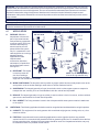
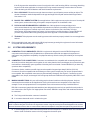
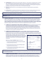
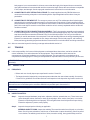
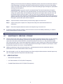
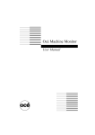
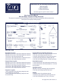
Instructions for the following series products:
Web Lanyards
Rope Lanyards
D-Ring Extensions
(See back pages for specific model numbers.)
User Instruction Manual
Web and Rope Lanyards, D-Ring Extension
This manual is intended to meet the Manufaturer’s Instructions as recommended by OSHA, and should be
used as part of an employee training program.
Figure 1 - Web and Rope Lanyards
DESCRIPTION
Nylon Rope Lanyards:
Adjustable 1/2 inch rope, self locking snap hook each end.
Adjustable 5/8 inch rope, self locking snap hook each end.
1/2 inch rope, self locking snap each end.
1/2 inch rope, self locking snap hook, carabiner other end.
5/8 inch rope, self locking snap hook each end.
Polyester Web Lanyards/D-Ring Extension:
Adjustable 1 inch web, self locking snap hook each end.
1 inch web, self locking snap hook each end.
1 inch web, self locking hook, D-ring (D-ring extension).
1 inch web, self locking snap hook, carabiner other end.
1 inch web, self locking snap hook, closed loop choker.
Polyester Rope Lanyards:
Adjustable 1/2 inch rope, self locking snap hook each end.
Adjustable 5/8 inch rope, self locking snap hook each end.
1/2 inch rope, self locking snap hook each end.
1/2 inch rope, self locking snap hook, carabiner other end.
5/8 inch rope, self locking snap hook each end.
Kevlar Web Lanyards:
1-3/4 inch Kevlar web, self locking snap hook each end.
1-3/4 inch Kevlar web, self locking snap hook, 1-3/16 inch
throat carabiner.
Nylon Web Lanyards:
Adjustable 1 inch web, self locking snap hook each end.
1 inch web, self locking snap hook each end.
Polyester Y-Lanyards:
1-3/4 inch polyester web, self locking snap hook each
end, spreader bar, center D-ring.
1-3/4 inch polyester web, self locking snap hook each
end, center D-ring.
Wristlets:
1 inch web, center O-ring, wrist loop each end.
1 inch web, Y style, center D-ring, wrist loop each end.
1 inch web, Detachable style, O-ring, 1 wrist loop.
1
© Copyright 2005, DB Industries, Inc.
WARNING: This product is part of a personal restraint, work positioning, suspension, or rescue system. The user must
read and follow the manufacturer's instructions for each component or part of the complete system. These instructions
must be provided to the user of this equipment. The user must read and understand these instructions or have them
explained to them before using this equipment. Manufacturer's instructions must be followed for proper use and
maintenance of this product. Alterations or misuse of this product or failure to follow instructions may result in serious
injury or death.
IMPORTANT: If you have questions on the use, care, application, or suitability for use of this equipment, contact DBI/SALA.
IMPORTANT: Before using this equipment record the product identification information (found on the I.D. label) in the
inspection maintenance log in section 9.0 of this manual.
1.0
1.1
APPLICATION
Figure 2 - Applications
PURPOSE: DBI/SALA
lanyards are to be used as
part of a personal restraint,
work positioning, suspension,
or rescue system. The D-ring
extension assembly may
also be used as part of a
personal fall arrest system
only if it is attached to a self
retracting lifeline or an energy
absorbing lanyard.
Applications include:
inspection work,
construction, demolition,
maintenance, oil production,
and confined space rescue.
See Figure 2.
A. RESTRAINT: The lanyard
is used to prevent the
user from reaching a
hazard, such as leading
edge work. No vertical free fall possible.
NOTE: The fall arrest application
is for the D-ring extension only.
B. WORK POSITIONING: The lanyard is used to position or support (with a harness or body belt) the user at the
work position, such as window washing or steel workers. Two feet maximum free fall.
C. SUSPENSION: The lanyard (generally a Y-type) is used with a chair or other support system to suspend or
transport the user vertically, such as in a boatswain’s chair. No vertical free fall possible.
D. RESCUE: The lanyard (generally a Y-type or wristlet) is used to retrieve a victim in a rescue, such as confined
space rescue and retrieval. No vertical free fall possible.
E. FALL ARREST: The D-ring extension is used in-line wih a personal fall arrest system to assist in attachment
to the system.
1.2
LIMITATIONS: The following application limitations must be recognized and considered before using this product:
A. CAPACITY: This equipment is for use by persons with a combined weight (person, clothing, tools, etc.) of no
more than 310 lbs.
B. FREE FALL: Lanyards used for work positioning applications must be rigged to minimize any potential
vertical free fall. In no case should the potential free fall be greater than two feet. For situations where the free
fall may exceed two feet, a backup fall arrest system should be used. The Y-lanyards and wristlets may only
be used where there is no possible vertical free fall.
2
If the D-ring extension assemblies are used in conjunction with a self retracting lifeline or an energy absorbing
lanyard in a fall arrest application, the length of the D-ring extension assembly must be taken into account
when calculating the free fall distance and the fall clearance requirements.
C. FALL CLEARANCE: Ensure that enough clearance exists in your fall path to prevent striking an object. The
amount of clearance needed is dependent on the type and length of the lanyard used and anchorage location.
See section 1.2 B.
D. BACKUP FALL ARREST SYSTEM: Some applications of this equipment may require the use of a backup fall
arrest system; such as when using a Y-lanyard to suspend a person in a boatswain’s chair.
E. PHYSICAL AND ENVIRONMENTAL HAZARDS: Use of this equipment in areas with physical or
environmental hazards may require additional precautions to reduce the possibility of injury to the user or
damage to the equipment. Hazards may include, but are not limited to; heat, chemicals, corrosive
environments, high voltage power lines, gases, moving machinery, and sharp edges. Contact DBI/SALA if
you have any questions about using this equipment where physical or environmental hazards exists.
F. TRAINING: This equipment must be used by persons who have been properly trained in its correct application
and use.
1.3
2.0
Refer to applicable local, state, and federal (OSHA) requirements governing this equipment for more information
on lanyards and associated system components.
SYSTEM REQUIREMENTS
2.1
COMPATIBILITY OF COMPONENTS: DBI/SALA equipment is designed for use with DBI/SALA approved
components and subsystems only. Substitutions or replacements made with non-approved components or
subsystems may jeopardize compatibility of equipment and may effect the safety and reliability of the complete
system.
2.2
COMPATIBILITY OF CONNECTORS: Connectors are considered to be compatible with connecting elements
when they have been designed to work together in such a way that their sizes and shapes do not cause their gate
mechanisms to inadvertently open regardless of how they become oriented. Contact DBI/SALA if you have any
questions about compatibility.
Connectors (hooks, carabiners, and D-rings) must be capable of supporting at least 5,000 lbs. (22.2 kN).
Connectors must be compatible with the anchorage or other system components. Do not use equipment that is
not compatible. Non-compatible connectors may unintentionally disengage. See Figure 3. Connectors must be
compatible in size, shape, and strength. Self locking snap hooks and carabiners are required by ANSI Z359.1 and
OSHA.
2.3
MAKING CONNECTIONS: Only use self-locking snap hooks and carabiners with this equipment. Only use
connectors that are suitable to each application. Ensure all connections are compatible in size, shape and
strength. Do not use equipment that is not compatible. Ensure all connectors are fully closed and locked.
DBI/SALA connectors (snap hooks and carabiners) are designed to be used only as specified in each product’s
user’s instructions. See Figure 4 for inappropriate connections. DBI/SALA snap hooks and carabiners should not
be connected:
A. To a D-ring to which another connector is attached.
B. In a manner that would result in a load on the gate.
NOTE: Large throat opening snap hooks should not be connected to standard size D-rings or similar objects which will
result in a load on the gate if the hook or D-ring twists or rotates. Large throat snap hooks are designed for use on fixed
structural elements such as rebar or cross members that are not shaped in a way that can capture the gate of the hook.
C. In a false engagement, where features that protrude from the snap hook or carabiner catch on the anchor and
without visual confirmation seems to be fully engaged to the anchor point.
3
Figure 3 - Unintentional Disengagement (Roll-out)
If the connecting element that a snap hook (shown) or carabiner attaches to is undersized or irregular in
shape, a situation could occur where the connecting element applies a force to the gate of the snap hook or
carabiner. This force may cause the gate (of either a self-locking or a non-locking snap hook) to open, allowing
the snap hook or carabiner to disengage from the connecting point.
Small ring or other
non-compatibly
shaped element
1. Force is applied to the
snap hook.
2. The gate presses against
the connecting ring.
3. The gate opens allowing the
snap hook to slip off.
D. To each other.
E. Directly to webbing or
rope lanyard or tieback (unless the
manufacturer’s
instructions for both
the lanyard and
connector specifically
allow such a
connection).
F.
2.4
Figure 4 - Inappropriate Connections
To any object which
is shaped or
dimensioned such
that the snap hook or
carabiner will not
close and lock, or
that roll-out could
occur.
ANCHORAGE
STRENGTH: The
anchorage strength required is dependent on the application type. The following are guidelines for some
application types:
A. RESTRAINT: Anchorages must support a minimum of 3,000 lbs. per person attached.
B. WORKING POSITIONING: Anchorages must support at least 3,000 lbs. per person attached; or be designed,
installed, and used under the supervision of a qualified person as part of a complete system, maintaining a
safety factor of at least two.
C. SUSPENSION: Anchorages must support a minimum of 2,500 lbs. per person attached.
D. RESCUE: Anchorages must support a minimum of 2,500 lbs. per person attached.
4
WARNING: Anchorages used for restraint, rescue, or suspension may only be used
where there is no possible vertical free fall. These anchorages do not have sufficient
strength for work positioning or fall arrest. Do not connect work positioning or fall
arrest systems to these anchorages. Anchorages intended for work positioning may
not be suitable for use for use for fall arrest systems (fall greater than two feet) and
should not be used for fall arrest unless specifically designed to do so.
3.0
Figure 5 - Hook Operation
OPERATION AND USAGE
WARNING: Do not alter or intentionally misuse this equipment. Consult DBI/SALA
when using this equipment in combination with components or subsystems other than
those described in this manual. Some subsystem and component combinations may
interfere with the operation of this equipment. Use caution when using this equipment
around moving machinery, electrical hazards, chemical hazards, and sharp edges.
WARNING: Consult your doctor if there is reason to doubt your fitness to safely absorb
the shock from a fall arrest. Age and fitness seriously affect a worker's ability to
withstand falls. Pregnant women and minors must not use this equipment.
3.1
BEFORE EACH USE of this equipment, carefully inspect it to assure that it is
in serviceable condition. Check for worn or damaged parts. Ensure that all
hardware is present and secure. Inspect for sharp edges, burrs, cracks, or
corrosion. Ensure self locking snap
Figure 6 - Anchorage
hooks or carabiners work properly. See
Figure 5. Inspect the rope or webbing
for wear, cuts, burns, frayed edges,
breaks, or other damage. Refer to
section 5.0 for further inspection
details. Do not use if inspection
reveals an unsafe condition.
3.2
PLAN your restraint, working
positioning, suspension, or rescue
system before starting your work.
Consider all factors that affect your
safety at any time during use. The
following list gives some important
points to consider when planing your
system.
A. ANCHORAGE: Select a rigid
anchorage point that is capable of
supporting the required loads. See
section 2.4. For work positioning systems, the anchorage location must be
selected to limit the free fall to two feet, to reduce swing fall hazards, and
to avoid striking an object during a fall. See Figures 6 and 7.
B. FREE FALL: Depending on the lanyard type and the application, the
allowable free fall ranges from no free fall to two feet. See section 1.2.B.
C. FALL CLEARANCE: Should a fall occur, there must be sufficient
clearance in the fall area to arrest the fall before striking the ground or
other objects.
D. BACKUP FALL ARREST: Some suspension and work positioning
applications of this equipment may require a backup fall arrest system
and independent fall arrest anchorage. See OSHA guidelines when
designing the system.
5
Figure 7 - Swing Fall
E. SHARP EDGES: Avoid working where the lanyard, subsystem, or other system components will be in contact
with, or abrade against unprotected sharp edges. Do not loop the lanyard around small diameter structural
members. If working with this equipment near sharp edges is unavoidable, protection against cutting must be
provided by using a heavy pad or other means over the exposed sharp edge.
F. RESCUE: Should a fall occur, the user (employer) must have a rescue plan and the means at hand to
implement it.
G. AFTER A FALL: Any equipment which has been subjected to the forces of arresting a fall must be removed
from service immediately and destroyed or contact a factory authorized service center for repair.
WARNING: Follow the manufacturer’s instructions for associated equipment (full body harness, workseat, etc.) used in
your restraint, work positioning, suspension, or rescue system.
IMPORTANT: For special (custom) versions of this product, follow the instructions herein. If included, see supplement for
additional instructions.
3.3
MAKING CONNECTIONS: Do not use hooks or connectors that will not completely close over the attachment
object. For these situations, use a “tie-off” adapter or other anchorage connector to allow a compatible connection.
Do not knot a lanyard in any manner. Do not attach a snap hook directly to a horizontal lifeline or to a webbing
loop. Lanyards with web loops must only be attached to other components with compatible connections. When a web
lanyard is used as a D-ring extension on a harness, connect the snap hook to the dorsal connector on the back of
the harness. Always follow the manufacturer’s instructions supplied with each system component.
A. CONNECTING TO ANCHORAGE OR ANCHORAGE CONNECTOR: When using a lanyard connect one end of
the lanyard to the full body harness. Connect other end of the lanyard to the anchorage or anchorage
connector. Ensure the connector (self locking snap hook or carabiner) is fully engaged and locked onto the
body support connecting point and anchorage or anchorage connector. See Figure 5 for operation of hooks.
Ensure connections are compatible in size, shape, and strength. See the manufacturer’s instructions for the
anchorage for more information on making connections.
B. CONNECTING TO THE BODY SUPPORT: For general restraint, connect the lanyard to the dorsal D-ring
between the shoulders on a full body harness. If using a body belt connect the lanyard to the D-ring and
position the belt so the D-ring is located on your back side. For positioning applications connect the lanyard to
the side D-rings or the front D-ring on the full body harness or body belt. Some full body harnesses incorporate
shoulder D-rings. A Y-lanyard may be connected to these for
Figure 8 - Web Loop Connection
rescue and suspension applications. Ensure the connections are
compatible in size, shape, and strength. See the body support
manufacturer’s instructions for more information on making
connections.
Attaching a Lanyard with Web Loops: See Figure 8.
1. Insert the energy absorbing lanyard web loop through the
harness web loop or the D-ring.
2. Insert the opposite end of the energy absorbing lanyard
through the connecting web loop.
3. Pull the attached energy absorbing lanyard through the
connecting web loop to secure it.
WARNING: Only compatible connections may be made with the connecting loops. Use of snap hooks (self locking and
non-locking types) may result in inadvertent disengagement from the web loops. Failure to follow these instructions may
result in serious injury or death.
C. CONNECTING TO A ROPE GRAB: For restraint or work positioning applications only. When connecting a
lanyard to a rope grab connect one end to the attachment point of the rope grab and connect the other end to
the body support. Some rope grabs may be supplied with a permanently attached lanyard or an energy
absorbing lanyard. For these cases, use of an additional lanyard connected between the rope grab and the
6
body support is not recommended. In all cases, ensure that the length of the lanyard does not exceed the
rope grab manufacturer’s recommended maximum connection length. Ensure the connections are compatible
in size, shape, and strength. See the rope grab manufacturer’s instructions for more information.
D. CONNECTING TO SELF RETRACTING LIFELINE: For restraint applications only. DBI/SALA does not
recommend connecting a lanyard to a self retracting lifeline. Special applications exist where it may be
permissible.
E. CONNECTING TO THE WRISTLET: For emergency rescue use only. The wristlets provide a limited support
and should only be used when other emergency rescue devices are impractical. Consult a qualified medical
personnel before using the wristlet. To use, place at wrist location. Locate wrist between the web strap and the
pad. Pull the web tight to secure the wrist. Make certain the wrist is securely captivated and the wristlet will
not slide or release.
F. CONNECTING TO THE D-RING EXTENSION ASSEMBLY: The D-ring extension assembly may be attached
to a self retracting lifeline or an energy absorbing lanyard for fall arrest applications only. The D-ring extension
snap hook should be connected to the dorsal D-ring on the full body harness. The D-ring on the extension
assembly is used for attachment of the snap hook on the self retracting lifeline or the energy absorbing lanyard.
Ensure the connections are compatible in size, shape, and strength. See the body support, self retracting
lifeline, and energy absorbing lanyard manufacturer’s instructions for more information on making connections.
3.4
4.0
4.1
After use return the lanyard for cleaning or storage as described in section 6.0.
TRAINING
It is the responsibility of all users of this equipment to understand these instructions, and to be trained in the
correct installation, use, and maintenance of this equipment. These individuals must be aware of the
consequences of improper installation or use of this equipment. This user manual is not a substitute for a
comprehensive training program. Training must be provided on a periodic basis to ensure proficiency of the users.
IMPORTANT: Training must be conducted without exposing the trainee to a fall hazard. Training should be repeated
periodically.
5.0
5.1
INSPECTION
FREQUENCY:
• Before each use visually inspect per steps listed in section 5.2 and 5.3
• The lanyard must be inspected by a competent person other than the user at least annually. See section
5.2 and 5.3 for guidelines. Record the results of each inspection in the inspection log found in section 9.0.
IMPORTANT: If this equipment has been subjected to forces resulting from the arrest of a fall, it must be immediately
removed from service and destroyed or returned to DBI/SALA for possible repair. See section 5.2.
IMPORTANT: Extreme working conditions (harsh environment, prolonged use, etc.) may require increasing the frequency
of inspections.
5.2
INSPECTION STEPS:
Step 1.
Inspect the lanyard hardware (snap hooks, adjusters, thimbles, spreader bar, etc.). These items must
not be damaged, broken, distorted, or have any sharp edges, burrs, cracks, worn parts, or corrosion.
Ensure the connecting hooks work properly. The hook gates must move freely and lock upon closing.
Ensure the adjusters, if present, work properly.
Step 2.
Inspect the lanyard per the following as applicable:
WEBBING AND STITCHING: Inspect the webbing. The material must be free of frayed, cut, or broken
fibers. Check for tears, abrasions, mold, burns, or discoloration. Inspect the stitching. Check for pulled
or cut stitches. The webbing must be free of knots, excessive soiling, heavy paint buildup, and rust
7
staining. Check for chemical or heat damage, indicated by brown, discolored, or brittle areas. Check for
ultraviolet damage, indicated by discoloration and the presence of splinters or slivers on the webbing
surface. All of these above factors are known to reduce the webbing strength. Damaged or questionable
webbing should be replaced.
SYNTHETIC ROPE: Inspect the rope for concentrated wear. The material must be free of frayed or
broken strands, cuts, abrasions, burns, and discoloration. The rope must be free of knots, excessive
soiling, heavy paint buildup, and rust staining. Rope splices must be tight, with five (5) full tucks, and
the thimbles must be held by the splice. Check for chemical or heat damage indicated by brown,
discolored, or brittle areas. Check for ultraviolet damage, indicated by discoloration and the presence of
splinters and slivers on the rope surface. All of the above factors are known to reduce the rope strength.
Damaged or questionable ropes should be replaced.
5.3
Step 3.
Inspect the labels. All labels must be present and fully legible. See section 8.0.
Step 4.
Inspect each system component or subsystem according to the associated manufacturer’s
instructions.
Step 5.
Record the inspection date and results on the inspection log. See section 9.0.
If inspection reveals a defective condition, remove the unit from service immediately and destroy, or contact a
factory authorized service center for repair.
IMPORTANT: Only DBI/SALA or parties authorized in writing may make repairs to this equipment.
6.0
MAINTENANCE - SERVICING - STORAGE
6.1
Clean the lanyard with water and a mild detergent solution. Wipe the hardware off with a clean, dry cloth, and hang
it to air dry. Do not force dry with heat. If you have any questions regarding the cleaning of this equipment, or
require more information contact DBI/SALA. An excessive buildup of dirt, paint, etc., may prevent the lanyard
from working properly, and in severe cases degrade the webbing or rope to a point where it has become weakened
and should be removed from service. If you have any questions concerning the condition of your lanyard, or have
any doubt about putting it into service, contact DBI/SALA.
6.2
Additional maintenance and servicing procedures (i.e. replacement parts) must be completed by a factory
authorized service center. Authorization must be in writing.
6.3
Store the lanyard in a cool, dry, clean environment out of direct sunlight. Avoid areas where chemical vapors may
exist. Thoroughly inspect the lanyard after extended storage.
7.0
SPECIFICATIONS
•
Meets OSHA requirements.
•
U.S. Patent Number 4,977,647 (9503175 snap hook)
•
Canadian Patent Number 2,027,787 (9503175 snap hook)
8
Rope Type
Nylon
Polyester
Web Type
Nylon
Polyester
Ployester
Lanyard
Material Length
1/2 inch diameter,
5,750 lbs. tensil
strength, or 5/8 inch
diameter, 9,350 lbs.
tensil strength, three
strand nylon rope
Fixed
Adjustable
1/2 inch diameter,
5,750 lbs. tensil
strength, or 5/8 inch
diameter, 9,000 lbs.
tensil strenth, three
strand polyester rope
Fixed
Adjustable
Lanyard
Material Length
1 inch wide adjustable,
9,000 lbs. tensil
strength, or 1 inch
wide fixed, 7,500 lbs.
tensil strength, latex
treated nylon web
Fixed
Adjustable
1 inch polyester
webbing, 9,800 lbs.
tensil strength
Fixed
Adjustable
1 3/4 inch ployester
webbing, 8,800 lbs.
tensil strength
Fixed
9
Hardware
Drop forged alloy steel
self locking snap hook
with 5,000 lbs. tensil
strength. Steel self
closing/locking
carabiner with 5,000
lbs. tensil strength.
Hardware
Drop forged alloy steel
self locking snap hook
with 5,000 lbs. tensil
strength. Steel self
closing/locking
carabiner with 5,000
lbs. tensil strength.
Drop forged alloy steel
link, (adjustable
models only), drop
forged steel D-ring
with 5,000 lbs. tensil
strength.
Drop forged alloy steel
self locking snap hook
and D-ring with 5,000
lbs. tensil strength.
Aluminum spreader
bar (Y-Lanyards only),
covered with nylon
tubular webbing.
8.0
8.1
LABELING
These labels must be present and fully legible:
10
9.0
INSPECTION AND MAINTENANCE LOG
DATE OF MANUFACTURE: _______________________________________________________________________
MODEL NUMBER: ______________________________________________________________________________
DATE PURCHASED: ________________________________________________________________________________
INSPECTION DATE
INSPECTION ITEMS
NOTED
CORRECTIVE ACTION
Approved By:
Approved By:
Approved By:
Approved By:
Approved By:
Approved By:
Approved By:
Approved By:
Approved By:
Approved By:
Approved By:
Approved By:
11
MAINTENANCE
PERFORMED
9.0
INSPECTION AND MAINTENANCE LOG
DATE OF MANUFACTURE: _______________________________________________________________________
MODEL NUMBER: ______________________________________________________________________________
DATE PURCHASED: ________________________________________________________________________________
INSPECTION DATE
INSPECTION ITEMS
NOTED
CORRECTIVE ACTION
Approved By:
Approved By:
Approved By:
Approved By:
Approved By:
Approved By:
Approved By:
Approved By:
Approved By:
Approved By:
Approved By:
Approved By:
12
MAINTENANCE
PERFORMED
9.0
INSPECTION AND MAINTENANCE LOG
DATE OF MANUFACTURE: _______________________________________________________________________
MODEL NUMBER: ______________________________________________________________________________
DATE PURCHASED: ________________________________________________________________________________
INSPECTION DATE
INSPECTION ITEMS
NOTED
CORRECTIVE ACTION
Approved By:
Approved By:
Approved By:
Approved By:
Approved By:
Approved By:
Approved By:
Approved By:
Approved By:
Approved By:
Approved By:
Approved By:
13
MAINTENANCE
PERFORMED
This instruction applies to the following models:
1001210
1001211
1001220
1001230
1001235
1001240
1104738
1200074
1200079
1200080
1201001
1201002
1201003
1201004
1201005
1201006
1201011
1201012
1201013
1201014
1201015
1201016
1201017
1201020
1201021
1201022
1201023
1201024
1201025
1201026
1201027
1201028
1201029
1201030
1201031
1201032
1201033
1201034
1201035
1201036
1201037
1201038
1201039
1201040
1201041
1201042
1201043
1201044
1201045
1201046
1201047
1201048
1201049
1201050
1201051
1201052
1201053
1201054
1201055
1201056
1201057
1201058
1201059
1201061
1201062
1201063
1201065
1201066
1201075
1201076
1201077
1201101
1201102
1201103
1201104
1201105
1201106
1201107
1201108
1201109
1201110
1201111
1201112
1201115
1201116
1201117
1201118
1201119
1201120
1201121
1201122
1201123
1201124
1201125
1201126
1201127
1201128
1201129
1201130
1201131
1201132
1201133
1201134
1201135
1201136
1201137
1201138
1201140
1201141
1201142
1201143
1201144
1201145
1201146
1201147
1201148
1201149
1201151
1201152
1201153
1201154
1201155
1201156
1201157
1201158
1201161
1201162
1201163
1201164
1201165
1201166
1201167
1201168
1201169
1201170
1201171
1201172
1201173
1201174
1201175
1201176
1201177
1201178
1201179
1201180
1201181
1201182
1201183
1201184
1201185
1201186
1201187
1201188
1201189
1201190
1201191
1201192
1201193
1201194
1201195
1201196
1201197
1201198
1201201
1201202
1201203
1201204
1201205
1201206
1201207
1201208
1201209
1201210
1201211
1201212
1201213
1201214
1201215
1201216
1201217
1201218
1201219
1201220
1201221
1201222
1201223
1201224
1201225
1201226
1201227
1201228
1201229
1201230
1201231
1201232
1201233
1201234
1201235
1201236
1201237
1201238
1201239
1201240
1201241
1201242
1201243
1201244
1201245
1201246
1201247
1201248
1201249
1201250
1201251
1201252
1201276
1201277
1201278
1201279
1201280
1201281
1201282
1201283
1201285
1201290
1201291
1201292
1201293
1201301
1201302
1201303
1201304
1201331
1201341
1201342
1201346
1201347
1201350
1201351
1201352
1201365
1201370
1201371
1201372
1201373
1201374
1201375
1201460
1201461
1201462
1201463
1201464
1201465
1201470
1201471
1201472
1201473
1201474
1201480
1201545
1201550
1201600
1201601
1201602
1201603
1201604
1201605
1201606
1201607
1201608
1201611
1201612
1201613
1201614
1201615
1201616
1201617
1201618
1201620
1201621
1201622
1202000
1202001
1202002
1202003
1202004
1202005
1202006
1202007
1202008
1202009
1202010
1202011
1202012
1202013
1202014
1202015
1202016
1202017
1202018
1202019
1202020
1202021
1202022
1202023
1202024
1202025
1202026
1202027
1202028
1202029
1202030
Additional model numbers may appear on the next printing of these instructions
14
1202031
1202032
1202033
1202034
1202035
1202036
1202037
1202038
1202039
1202040
1202041
1202042
1202043
1202044
1202045
1202046
1202047
1202048
1202049
1202050
1202051
1202052
1202053
1202054
1202055
1202056
1202057
1202058
1202059
1202060
1202061
1202062
1202063
1202064
1202065
1202066
1202067
1202068
1202069
1202070
1202071
1202072
1202073
1202074
1202075
1202076
1202101
1202102
1202103
1202105
1202106
1202107
Continued from previous page . . .
1202108
1202120
1202121
1202122
1202123
1202124
1202125
1202126
1202127
1202128
1202129
1202130
1202131
1202132
1202133
1202134
1202135
1202136
1202137
1202138
1202139
1202140
1202141
1202142
1202143
1202144
1202145
1202146
1202147
1202148
1202149
1202150
1202151
1202152
1202153
1202154
1202155
1202156
1202157
1202158
1202159
1202160
1202161
1202162
1202163
1202164
1202165
1202166
1202167
1202168
1202169
1202170
1202171
1202201
1202202
1202203
1202204
1202205
1202206
1202207
1202208
1202209
1202210
1202211
1202212
1202213
1202214
1202215
1202216
1202217
1202218
1202219
1202220
1202221
1202222
1202223
1202224
1202225
1202226
1202227
1202228
1202229
1202230
1202231
1202232
1202233
1202234
1202235
1202236
1202237
1202238
1202239
1202240
1202241
1202242
1202243
1202244
1202245
1202246
1202247
1202248
1202249
1202250
1202251
1202252
1202253
1202254
1202255
1202256
1202257
1202258
1202259
1202260
1202261
1202262
1202263
1202264
1202265
1202266
1202267
1202268
1202269
1202270
1202271
1202272
1202273
1202274
1202275
1202276
1202277
1202278
1202301
1202302
1202303
1202304
1202305
1202306
1202307
1202308
1202309
1202310
1202311
1202312
1202313
1202314
1202315
1202316
1202317
1202318
1202319
1202320
1202321
1202322
1202323
1202324
1202325
This instruction applies to the following models:
1202326
1202327
1202328
1202329
1202330
1202331
1202332
1202333
1202334
1202335
1202336
1202337
1202338
1202339
1202340
1202341
1202342
1202343
1202344
1202345
1202346
1202347
1202348
1202349
1202350
1202351
1202352
1202353
1202354
1202355
1202356
1202357
1202358
1202359
1202360
1202361
1202362
1202363
1202364
1202365
1202366
1202367
1202368
1202369
1202370
1202371
1202372
1202373
1202374
1202375
1202376
1202377
1202378
1202379
1202380
1202381
1202382
1202383
1202384
1202385
1202386
1202387
1202388
1202389
1202390
1202391
1202392
1202393
1202394
1202395
1202396
1202397
1202398
1202399
1202400
1202401
1202402
1202403
1202404
1202405
1202406
1202407
1202408
1202409
1202410
1202411
1202412
1202413
1202414
1202415
1202416
1202417
1202418
1202419
1202420
1202421
1202422
1202423
1202424
1202425
1202426
1202427
1202428
1202429
1202430
1202431
1202432
1202433
1202434
1202435
1202436
1202437
1202438
1202439
1202440
1202441
1202442
1202443
1202444
1202445
1202446
1202447
1202448
1202449
1202450
1202451
1202452
1202453
1202454
1202455
1202456
1202457
1202458
1202459
1202460
1202461
1202462
1202463
1202464
1202465
1202466
1202467
1202468
1202469
1202470
1202471
1202472
1202473
1202474
1202475
1202476
1202477
1202478
1202479
1202480
1202481
1202482
1202483
1202484
1202485
1202486
1202487
1202488
1202489
1202490
1202491
1202492
1202493
1202494
1202495
1202496
1202497
1202498
1202499
1202500
1202501
1202502
1202503
1202504
1202505
1202506
1202507
1202508
1202509
1202510
1202511
1202512
1202513
1202514
1202515
1202516
1202517
1202518
1202519
1202520
1202521
1202522
1202523
1202524
1202525
1202526
1202527
1202528
1202529
1202530
1202531
1202532
1202533
Additional model numbers may appear on the next printing of these instructions
15
Continued from previous page . . .
1202534
1202535
1202536
1202537
1202538
1202539
1202540
1202541
1202542
1202620
1202630
1202691
1202692
1202693
1202694
1202696
1202697
1204005
1221501
1221601
This instruction applies to the following models:
3511645
5002030
5002031
5002032
5002033
5900021
5900022
5900023
5900024
5900105
1201064C
1201211C
1201233C
1201609C
1201610C
1201619C
1202684C
1202685C
Z1201016
Z1201018
Z1202403
Z1202404
Z1202411
Z1202419
Z1202420
Z1202431
Z1202432
Z1202446
Z1202447
Z1202474
Z1202476
Z1202501
Z1202502
Z1202514
Z1202515
Z1202667
Z1202672
Z1202673
Z1201060
Z1201106
Z1201150
Z1201160
Z1201199
Z1201200
Z1202320
Z1202321
Z1202334
Z1202335
Z1202345
Z1202346
Z1202361
Z1202363
Z1202373
Z1202374
Z1202386
Z1202387
Z1202392
Z1202393
Additional model numbers may appear on the next printing of these instructions
USA
Canada
3965 Pepin Avenue
Red Wing, MN 55066-1837
Toll Free: 800-328-6146
Phone: (651) 388-8282
Fax: (651) 388-5065
www.salagroup.com
260 Export Boulevard
Mississauga, Ontario L5S 1Y9
Toll Free: 800-387-7484
Phone: (905) 795-9333
Fax: (905) 795-8777
www.salagroup.com
This instruction manual is available for download at www.salagroup.com
I S O
9001
Certificate No. FM 39709
16
Form: 5902126
Rev: G