1
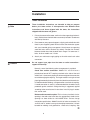
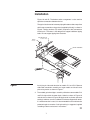
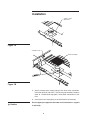
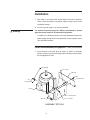
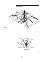
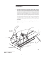
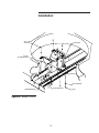
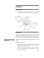
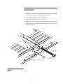
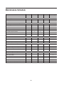
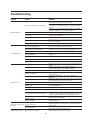
®
User Manual
Models P11 through P15
Manual 04-131
Contents
▲ Note
This manual contains vital information for the proper installation and
operation of your cooling tower. Carefully read the manual before
installation or operation of the tower and follow all instructions. Save
this manual for future reference.
Tower Location ...................................................................................... 4
Tower Shipment ..................................................................................... 5
Receiving Tower .................................................................................... 5
Hoisting Tower ....................................................................................... 5
Tower Installation ................................................................................... 6
Field Installed Mechanical Equipment ................................................... 9
Vibration Switch Option ....................................................................... 16
Basin Heater Option ............................................................................ 16
Tower Start-Up ..................................................................................... 18
Tower Operation .................................................................................. 21
Winter Operation .................................................................................. 23
Tower Cleaning, Water Treatment and Blowdown .............................. 26
Cleaning ............................................................................................... 27
Belt Replacement ................................................................................ 29
Belt Tensioning .................................................................................... 30
Sheave Alignment ................................................................................ 31
Schedule of Tower Maintenance ......................................................... 31
Seasonal Shutdown Instructions ......................................................... 33
Prolonged Shutdown ........................................................................... 34
Marley Services ................................................................................... 35
Maintenance Schedule ........................................................................ 36
Troubleshooting ................................................................................... 37
The following defined terms are used throughout this manual to bri
attention to the presence of hazards of various risk levels, or to important
information concerning the life of the product.
▲ Warning
Indicates presence of a hazard which can cause severe personal
injury, death or substantial property damage if ignored.
▲ Caution
Indicates presence of a hazard which will or can cause personal
injury or property damage if ignored.
▲ Note
Indicates special instructions on installation, operation or
maintenance which are important but not related to personal injury
hazards.
2
Preparation
The Marley Primus cooling tower purchased for this installation represents
the current state of the art in crossflow, induced draft cooling tower design.
Thermally and operationally, it is the most efficient cooling tower of its
class.
These instructions—as well as those offered separately on motors, fans,
float valves, etc.—are intended to assure that the tower serves you
properly for the maximum possible time. Since product warrantability may
well depend upon your actions, please read these instructions thoroughly
prior to operation.
If you have questions about the operation and/or maintenance of this
tower, and you don’t find the answers in this manual, please contact your
Marley sales representative. When writing for information, or when ordering
parts, please mention tower serial number shown on the nameplate
located on the access door.
Safety First
The location and orientation of the cooling tower can affect the safety of
those responsible for installing, operating or maintaining the tower. However,
since Marley does not determine the location or orientation of the tower, we
cannot be responsible for addressing those safety issues that are affected
by the tower’s location or orientation.
▲ Warning
The following safety issues should be considered by those responsible
for designing the tower installation.
• access to and from maintenance access doors
• the possible need for ladders (either portable or permanent) to
gain access to the distribution basin or maintenance access doors
• potential access problems due to obstructions surrounding the
tower
• lockout of mechanical equipment
• the possible need for safety cages around ladders
• the need to avoid exposing maintenance personnel to the potentially
unsafe environment inside the tower.
▲ Note
It is not intended nor assumed that access to the fan deck is needed
or necessary.
3
Preparation
▲ Note
Those are only some of the safety issues that may arise in the design
process. Marley strongly recommends that you consult a safety
engineer to be sure that all safety considerations have been addressed.
Tower Location
Space available around the tower should be as generous as possible to
promote ease of maintenance—and to permit freedom of airflow into and
through the tower. If you have questions about the adequacy of the
available space and the intended configuration of the tower, please
contact your Marley sales engineer for guidance.
Prepare a stable, level support foundation for the tower, utilizing weight,
wind load, and dimensional information appearing on appropriate Marley
literature. Supports must be level to insure proper operation of the tower.
▲ Warning
The cooling tower must be located at such distance and direction to
avoid the possibility of contaminated tower discharge air being
drawn into building fresh air intake ducts. The purchaser should
obtain the services of a Licensed Professional Engineer or Registered
Architect to certify that the location of the tower is in compliance with
applicable air pollution, fire, and clean air codes.
4
Receiving and Hoisting
Tower Shipment
Unless otherwise specified, Primus towers ship by truck (on flat bed
trailers), which lets you receive, hoist, and install the tower in one
continuous operation. Single-cell towers ship on one truck. Multicell
towers, depending on the quantity, may require more than one truck.
Responsibility for the condition of the tower upon its arrival belongs to the
trucker—as does the coordination of multiple shipments, if required.
Receiving Tower
Prior to unloading the tower from the delivering carrier, inspect the
shipment for evidence of damage in transit. If damage is apparent, note the
freight bill accordingly. This will be needed to support any future recovery
claim.
Find and remove the installation instructions and manuals (literature kit)
located in a plastic bag in the cold water basin. This information should be
kept for future reference and maintenance purposes.
Hoisting Tower
All models ship in a single module. A Hoisting-Installation label is located
on the side casing near the access door. Remove tower from the carrier
and hoist into place according to the instructions on the label.
5
Installation
Tower Installation
▲ Note
These installation instructions are intended to help you prepare
before your tower arrives. If discrepancies exist between these
instructions and those shipped with the tower, the instructions
shipped with the tower will govern.
1. Prior to placement of the tower, confirm that the supporting platform is
level, and that the anchor bolt holes are correctly located in accordance
with Marley literature.
2. Place tower on your prepared supports, aligning anchor bolt holes with
those in your supporting steel. Make sure that the orientation agrees
with your intended piping arrangement. Attach tower to supporting
steel with bolts and flat washers (by others). Position flat washers
between the bolt head and the tower basin flange. P11 tower use ³⁄₈"
bolts, all other models use ¹⁄₂" bolts.
3. Attach your cold water supply piping to the cold water basin outlet
connection.
▲ Caution
Do not support your pipe from the tower or outlet connection—
support it externally.
Normally, one of the following outlet arrangements is provided:
Cased face suction connection: Models P11 and P12 have a
polyethylene female NPT coupling attached to the side of the cold
water basin. It is extremely important not to overtighten the connection
to avoid damaging the coupling. The larger models have a galvanized
pipe nipple extending horizontally from the side of the cold water basin.
It is both beveled for welding—and grooved for a mechanical coupling.
If a weld connection is used, it is recommended that the weld area be
protected against corrosion. Cold galvanizing is suggested, applied
according to the manufacturer’s instructions. Install 2" plugs in outlets
that are not used.
Bottom outlet connection option: This is a factory-installed, circular
opening in the cold water basin floor. An appropriately-sized circular
opening has been drilled to 125# ASME B16.1 flat-face flange
connection specifications. Model P13 with 10" outlet and models P14
and P15 with 12" outlets have a galvanized pipe connection. It is both
beveled for welding—and grooved for a mechanical coupling. See
➠
6
Installation
Figure 1A and 1B. The bottom outlet arrangement is also used for
equalizer connections between basins.
The typical attachment of customer piping for bottom outlet or equalizer
with flange connection using gasket (supplied by Marley) is shown in
Figure1. Sealing washers (by others) required at bolt connections
inside basin. The tower is not designed to support additional piping
loads. Do not support piping from the tower.
PLUG
P11-P12
COVER PLATE
P13-P14-P15
TRASH SCREEN
GASKET
Figure 1
Install plug in side-outlet location for models P11 and P12. Remove
side-outlet connection assembly on larger models and install cover
plate using sealer as shown in Figure 1.
4. The welded galvanized pipe assembly utilized on some models P14
and P15 ships within the tower basin. Unbolt as shown in Figure 1A
and reinstall as shown in Figure 1B. Apply sealer as shown and reuse
existing hardware as well as additonal hardware shipped with tower.
If a weld connection is used, it is recommended that the weld area be
protected against corrosion. Cold galvanizing is suggested, applied
according to the manufacturer’s instructions.
➠
7
Installation
UNBOLT AND
REINSTALL
Figure 1A
COVER PLATE
TRASH SCREEN
Figure 1B
5. Attach makeup water supply piping to the float valve connection.
Install the float ball and stem. If you wish to pipe overflow and drain
water to a remote discharge point, make those connections at this
time.
6. Install your warm water piping at the inlet location on the tower.
▲ Caution
Do not support your pipe from the tower or inlet connection—support
it externally.
8
Installation
7. Wire motor in accordance with wiring diagram on motor nameplate.
Check motor connections and power supply voltage versus motor
nameplate voltage.
8. Install fan guard using ³⁄₈" tap screws provided.
For maintenance/safety purposes, Marley recommends a lockout
type disconnect switch for all mechanical equipment.
▲ Warning
In addition to a disconnect switch, the motor should be wired to main
power supply through short circuit protection, and a magnetic starter
with overload protection.
Field Installed Mechanical Equipment—Direct Drive Models
1. Install brackets and motor plate to motor as shown in Assembly
Details. If present, remove drain plugs from the bottom of the motor on
the end opposite of shaft.
LOCK WASHER
3/8" X 1" BOLT
BRACKET
NUT
LOCK WASHER
NUT
FLAT WASHER
MOTOR
MOTOR PLATE
3/8" X 1 1/2" BOLT
BRACKET
ASSEMBLY DETAILS
9
Installation
B
A
Figure 2
2. Install motor assembly on tower cross beams as shown in Figure 2 and
Detail A. Leave bolts loose enough to allow for fan centering adjustment.
3/8" X 1" BOLT
3 PLACES
BRACKET
FLAT WASHER
MOTOR
LOCK WASHER
FLAT WASHER
NUT
DETAIL A
➠
10
Installation
3. Install the fan bushing loosely in the fan and install the fan assembly
onto the motor shaft. Install motor key. See Detail B and Figure 2.
Bushing is to be flush with the end of the motor shaft. Tighten bushing
bolts. See page 31 for torque specifications.
MOTOR KEY
BUSHING AND
HARDWARE
FAN
DETAIL B
4. Adjust assembly so that fan is centered in fan opening. Tighten bracket
bolts. See Detail A.
5. Apply Loctite 242 to all fasteners except bushing hardware. Do not
apply to tensioning nut.
11
Installation
Field Installed Motor—Belt Drive Models
1. Install brackets and motor plate to motor as shown in Assembly
Details. Install sheave (and bushing models P13 through P15) to motor
shaft. Leave sheave loose enough to allow for sheave adjustment
later. If present, remove drain plugs from the bottom of the motor on
the end opposite of shaft.
MOTOR KEY
MOTOR SHEAVE
1/2" X 6"
ALLTHREAD BOLT
1/2" X 1" BOLT
BRACKET
MOTOR
NUT
BRACKET
LOCK WASHER
MOTOR PLATE
MOTOR BOLT
(SIZE VARIES)
JAM NUT
ASSEMBLY DETAILS
MODEL P12
➠
12
Installation
MOTOR KEY
MOTOR SHEAVE
BUSHING
1/2" X
6"
ALLTHREAD BOLT
1/2" X
MOTOR SHEAVE
1" BOLT
BRACKET
MOTOR
NUT
LOCK WASHER
BRACKET
MOTOR PLATE
MOTOR BOLT
(SIZE VARIES)
JAM NUT
ASSEMBLY DETAILS
MODELS P13 THROUGH P15
2. Install motor assembly on tower cross beams as shown in Figure 3.
Slide toward the fan shaft assembly. Do not install bolts yet.
3. The fan sheave may have belt grooves that are not used. The motor
sheave will always have the correct number of grooves for your tower
model. The bottom surface of the motor and fan sheaves must be
aligned with ¹⁄₁₆" of each other and level within ¹⁄₂° (¹₈" in 12″) in order
to not adversely affect belt and sheave life.
Alignment can be achieved by placing a straight edge across the top
of the fan sheave—making sure that it is level—and measuring down
to the bottom surface of both sheaves at four points. Align by moving
only the motor sheave. Tighten the motor sheave bushing hardware
after alignment. See page 31 for torque specifications.
13
Installation
4. Install belts on the lowest set of grooves. Slide the motor assembly
away from fan shaft and to remove belt slack and install bolts in tower
cross beams. Do not tighten at this time. Install the 6″ all-thread bolt
on the motor plate and adjusting clip as shown in the Assembly Details
and Figure 3 or Figure 3A. Adjusting clip may have to be relocated to
another set of holes. Tighten the tensioning nut on the all-thread bolt
at the adjusting clip to tension belts. Proper tension is achieved when
a belt deflects about ¹₄" under a force of 5 to 7 pounds. Tighten jam
nut against the adjusting clip to lock adjustment. Tighten bolts in tower
cross beam.
5. Apply Loctite 242 to all fasteners except bushing hardware. Do not
apply to tensioning nut.
FAN SHAFT
3/8" X 1" BOLT
4 PLACES
1/2" X 6"
ALLTHREAD BOLT
LOCK WASHER
NUT
JAM NUT
ADJUSTING CLIP
TENSIONING NUT
➠
Figure 3 Model P12
14
Installation
3/8" X
1" BOLT
4 PLACES
FAN SHAFT
1/2" X 6"
ALLTHREAD BOLT
JAM NUT
LOCK WASHER
ADJUSTING CLIP
TENSIONING NUT
Figure 3A Model P13-P15
15
NUT
Installation
Vibration Switch
1. Install vibration to the inside of the tower cross beam as shown. Refer
to instructions that ship with the vibration switch for wiring information.
1/4" X 1 1/2"
ALL THREAD BOLT
WASHER
LOCK WASHER
NUT
VIBRATION SWITCH
Basin Heater
All basing heater components must be field installed and wired by others.
Installation must meet requirements of latest national electrical code and
local codes. Heater package components consist of an enclosure, magnetic
contactor, circuit board, transformer, heater element, and control probe.
▲ Warning
Failure to follow the Basin Heater installation procedure may result
in fire.
Control Box components:
Transformer–steps down line voltage to 24 volts for control circuit.
Magnetic Contactor–controls power to heater. Contacts are rated for
line voltage. Coil is rated for 24 volt circuit
Control Probe–senses water temperature and controls the contactor
to maintain set water temperature. Prevents the contactor from closing
when water level is too low.
➠
16
Installation
1. Field drill an 1¹⁄₈" hole in location shown and install control probe in the
bulkhead fitting. Use pipe joint compound on threads.
2. Install heater element as shown in Figure 4.
3. Attach heater support as shown in Figure 4.
4. The basin heater control box is to be located and installed outside of
the cooling tower. Control probe cord length of 12'-0" may restrict
control box location.
BULKHEAD FITTING
WITH GASKET
HEATER
ELEMENT
CONTROL PROBE
1 1/8" HOLE
Figure 4
17
PROBE CORD
TO CONTROL BOX
Operation
Tower Start-Up
▲ Warning
Among other sources, outbreaks of Legionnaires’ Disease have
reportedly been traced to cooling towers. Maintenance and water
treatment procedures that prevent amplification and dissemination
of Legionella and other airborne bacteria should be formulated and
implemented BEFORE systems are operated and continued regularly
thereafter to avoid the risk of sickness or death.
Water System:
1. New installations should be cleaned and treated with biocides by a
water treatment expert before start-up.
2. Remove any and all accumulated debris from tower. Pay particular
attention to inside areas of cold water basin, hot water basins, louvers
and drift eliminators. Make sure that cold water suction screens are
clear and properly installed.
3. Fill the water system to an approximate depth of 6″ (152 mm) in the
depressed area of the cold water basin at the air inlet side of the tower.
This is the recommended operating water level. Adjust the float valve
so that it is 75% open at that level. Continue filling the system until the
water reaches a level approximately ¹⁄₈″ (3 mm) below the lip of the
overflow. Normal water operating level is 5" for model P11, 6" for
models P12 and P13 and 7" for models P14 and P15.
▲ Note
If tower is equipped with a standard suction connection, vent
accumulated air from the top of the suction hood by removing the tap
screw provided at that location. Replace tap screw when venting is
complete.
4. Start pump(s) and observe system operation. Since the water system
external to the tower will have been filled only to the level achieved in
the cold water basin, a certain amount of “pump-down” of the basin
water level will occur before water completes the circuit and begins to
fall from the fill. The amount of initial pump-down may be insufficient
to cause the float valve to open. However, you can check its operation
by pressing down on the operating lever to which the stem of the float
valve is attached.
➠
18
Operation
Some trial-and-error adjustment of the float valve may be required to
balance the makeup water with tower operation. Ideally, the float valve
setting will be such that no water is wasted through the overflow at
pump shutdown. However, the water level after pump start-up must be
deep enough to assure positive pump suction.
5. Uniform distribution basin depth of 2³⁄₄″ to 5¹⁄₂″ (70 mm to 140 mm) is
essential to efficient tower operation. Contact your Marley sales
representative if you are considering a permanent change in circulating
water flow rate that would prevent operation within these limits.
6. Continue pump operation for about 15 minutes, after which it is
recommended that the water system be drained, flushed, and refilled.
7. While operating the condensing water pump(s) and prior to operating
the cooling tower fan, execute one of the two alternative biocidal
treatment programs described in the following:
• Resume treatment with the biocide which had been used prior to
shutdown. Utilize the services of the water treatment supplier. Maintain
the maximum recommended biocide residual (for the specific biocide)
for a sufficient period of time (residual and time will vary with the
biocide) to bring the system under good biological control
or
• Treat the system with sodium hypochlorite to a level of 4 to 5 mg/L
(ppm) free chlorine residual at a pH of 7.0 to 7.6. The chlorine residual
must be held at 4 to 5 mg/L (ppm) for six hours, measurable with
standard commercial water test kits.
If the cooling tower has been in operation and then shut down for a
duration of time and not drained, perform one of the two previous
biocidal treatment programs directly to the cooling water storage
vessel (cooling tower sump, drain down tank, etc.) without circulating
stagnant water over the cooling tower fill or operating the cooling tower
fan. After biocidal pretreatment has been successfully completed,
cooling water may be circulated over the tower fill with the fan off.
When biocidal treatment has been maintained at a satisfactory level
for at least six hours, the fan may be turned on and the system returned
to service. Resume the standard water treatment program, including
biocidal treatment.
19
Operation
Mechanical Equipment:
▲ Warning
Always shut off electrical power to the tower fan motor prior to
performing any maintenance on the tower. Any electrical switches
should be locked out and tagged out to prevent others from turning
the power back on.
1. Spin the fan manually to assure that all fan blades properly clear the
inside of the fan cylinder. On belt-drive models observe the action of
the sheaves and belt(s) to be sure that the motor is properly aligned
with the fan sheave. If necessary, correct the alignment. See the
Maintenance section for belt tensioning and sheave alignment—
pages 30 and 31.
2. Momentarily energize (“bump”) the motor and observe rotation of the
fan. The fan should rotate in a counterclockwise direction when viewed
from above. If rotation is backwards, shut off the fan and reverse two
of the three primary leads supplying power to the motor.
▲ Caution
If tower is equipped with a two-speed motor, check for proper rotation
at both speeds. Check also to see that starter is equipped with a
20 second time delay which prevents direct switching from high
speed to low speed. If the fan is intended to be reversed for deicing
purposes, make sure that the starter is equipped with a 2 minute time
delay between changes of direction. These delays will prevent
abnormal stress from being applied to the mechanical equipment
and the electrical circuit components.
3. Run the motor and observe the operation of the mechanical equipment.
Operation should be stable.
4. After the first 30 minute run check motor amps and voltage with full
water and heat load. Refer to motor manual.
5 . After 10 to 60 hours of operation check the torque on the fan and motor
sheave bushings and check belt tension on belt-drive models. Refer
to the Maintenance section of this manual for torque values and belt
tensioning instructions—pages 30 and 31.
➠
20
Operation
▲ Note
If the water supply system is not being operated—or if there is no heat
load on the system—motor amps read at this time may indicate an
apparent overload of as much as 10–20%. This is because of the
increased density of unheated air flowing through the fan.
Determination of an accurate motor load should await the application
of the design heat load.
Tower Operation
General:
The cold water temperature obtained from an operating cooling tower will
vary with the following influences:
1. Heat load: With the fan in full operation, if the heat load increases, the
cold water temperature will rise. If the heat load reduces, the cold water
temperature will reduce.
Note that the number of degrees (“range”) through which the tower
cools the water is established by the system heat load and the amount
of water being circulated, in accordance with the following formula:
Range ° F
=
Heat Load (Btu/hr)
GPM x 500
or in SI units
Range ° C
=
Heat Load (kilowatts)
Liters/sec x 4.187
The cooling tower establishes only the cold water temperature attainable
under any operating circumstance.
2. Air wet-bulb temperature: Cold water temperature will also vary with
the wet-bulb temperature of the air entering the louvered faces of the
tower. Reduced wet-bulb temperatures will result in colder water
temperatures. However, the cold water temperature will not vary to the
same extent as the wet-bulb. For example, a 20°F (11 °C) reduction in
wet-bulb may result in only a 15°F (8°C) reduction in cold water
temperature.
➠
21
Operation
3. Water flow rate: Increasing the water flow rate (GPM or L/s) will cause
a slight elevation in cold water temperature, while reducing the water
flow rate will cause the cold water temperature to decrease slightly.
However, at a given heat load (see formula above), water flow
reductions also cause an increase in the incoming hot water
temperature. Use care to prevent the hot water from exceeding 120°F,
(49°C) in order to prevent damage to the tower components.
4. Air flow rate: Reducing air flow through the tower causes the cold
water temperature to rise. This is the approved method by which to
control leaving water temperature.
If your tower is equipped with a single-speed motor, the motor may be
shut off when the water temperature becomes too cold. This will cause
the water temperature to rise. When the water temperature then
becomes too warm for your process, the motor can be restarted.
▲ Caution
When operating in this mode care must be taken not to exceed a total
acceleration time of 30 seconds per hour.
Fan cycling limits: From a dead stop, determine the number of
seconds it takes the fan to arrive at full speed. Divide this number into
30 to determine the allowable number of starts per hour. Considering
the normal fan and motor sizes utilized on Primus towers, anticipate
that approximately 4 to 5 starts per hour are allowable.
If your tower is equipped with a two-speed motor, you will enjoy greater
opportunity for temperature control. When the water temperature
becomes too cold, switching the fan to half-speed will cause the cold
water temperature to rise—stabilizing at a temperature a few degrees
higher than before. With a further reduction in water temperature, the
fan may be cycled alternately from half-speed to off—subject to the
same constraint of 30 seconds of allowable acceleration time per hour
as outlined above.
If your tower consists of two or more cells, cycling of motors may be
shared between cells, increasing your steps of operation accordingly.
For greater insight on cold water temperature control, please read
“Cooling Tower Energy and its Management,” Marley Technical
Report #H-001-A, available from your Marley sales representative.
22
Operation
Wintertime Operation:
The Marley fill system used in the Primus cooling tower has air entrance
louvers that are molded integrally as part of the fill. This feature makes
these towers very forgiving of cold weather operation, even at the low
temperature and reduced load conditions encountered in free cooling and
other low temperature applications. Nevertheless, during operation in
subfreezing weather the opportunity exists for ice to form in the colder
regions of the tower.
▲ Note
Slushy, transitory ice forms routinely in the colder regions of the fill
of low temperature towers, and is visible through the tower louvers.
Such ice normally has no adverse effect on tower operation, but its
appearance should be a signal to the operator to undertake ice
control procedures.
It is the operator's responsibility to prevent the formation of destructive
(hard) ice on the cooling tower fill. Certain guidelines should be
followed:
1. Do not allow the tower’s leaving water temperature to drop below a
minimum allowable level—say 36°F to 40°F (2°C to 4.5°C). If such low
temperature operation is necessary or beneficial to your process,
establish the minimum allowable level as follows:
During the coldest days of the first winter of operation, observe
whether any ice is forming on the louver face, particularly near the
bottom part of the louver face. If hard ice is present on the louvers, you
must increase the allowable cold water temperature. If the coldest
possible water is beneficial to your process, ice of a mushy consistency
can be tolerated—but routine periodic observation is advisable.
▲ Caution
If the minimum allowable cold water temperature is established at or
near maximum heat load, it should be safe for all operating conditions.
However, if established at reduced load, increased heat loads may
reintroduce the potential for icing.
Having established the minimum allowable cold water temperature,
maintaining that temperature can be accomplished by fan manipulation,
as outlined in Item 4 under Tower Operation page 22. However, in
towers of more than one cell, where fans are manipulated sequentially,
➠
23
Operation
please realize that the water temperature will be significantly lower in
the cell or cells operating at the highest fan speed than the net cold
water temperature produced by the entire tower would indicate.
Wintertime operation of multicell towers at low cold water temperature
levels requires that the operator be especially watchful.
2. As cold air enters the louvers, it causes the water flowing over the fill
to be drawn inward toward the center of the tower. Thus, under fan
operation, the louvers and lower periphery of the tower structure
remain partly dry, seeing only random splashing from within the
tower—plus normal atmospheric moisture from the entering air. Such
lightly wetted areas are most subject to freezing.
Therefore, if excessive ice forms on the louvers, stop the fan for a few
minutes. With the fan off, the water flow will increase in the vicinity of
the louvers and reduce the ice buildup.
3. Under extended extreme cold conditions, it may be necessary to
operate the fan in reverse. This forces warm air out through the
louvers, melting any accumulated ice—adequate heat load must be
available. Reversal may be at either full or half speed; however, Marley
recommends reversal at half speed. Reverse operation of the fan
should be used sparingly and should only be used to control ice, not
to prevent it. Reverse fan operation should not need to exceed 1 or 2
minutes. Monitoring is required to determine the time required to melt
accumulated ice.
▲ Warning
Reverse operation of fans for prolonged periods during subfreezing
weather can cause severe damage to fans and fan cylinders. Ice can
accumulate inside fan cylinders at fan blade plane of rotation and fan
blade tips will eventually strike this ring of ice, damaging the fan
blades or cylinder. Ice can also accumulate on fan blades and be
thrown off, damaging fan cylinder or blades. Allow a minimum of 10
minute delay between reverse operation and forward operation
during subfreezing weather to permit ice to dissipate from fan blades
and fan cylinders. See Caution note on page 20 for fan speed change
and reversing precautions.
➠
24
Operation
4. With no heat load on the circulating water, icing cannot be controlled
effectively by air control during freezing weather. Towers must not be
operated with reduced water rate and/or no heat load during
freezing weather. If the circulating water system cannot be shut
down, water returning from the process should be made to bypass the
tower. If a bypass is used, all water must be bypassed without
modulation. If the water bypass is directly into the tower's cold water
basin, its design must be approved by Marley Engineers.
Intermittent Wintertime Operation:
If periods of shutdown (nights, weekends, etc.) occur during freezing
weather, measures must be taken to prevent the water in the cold water
basin—and all exposed pipework—from freezing. Several methods are
used to combat this, including automatic basin heater systems available
from Marley.
▲ Caution
Unless some means of freeze prevention is incorporated into your
system, the tower basin and exposed pipework should be drained at
the beginning of each wintertime shutdown period.
▲ Warning
If tower basin is drained, verify that all basin heaters have been shut
off either by automatic cutoff or disconnect switch.
It is recommended that you discuss your freeze prevention options with
your local Marley sales representative.
25
Maintenance
Tower Cleaning, Water Treatment and Blowdown
Maintaining Water Quality:
The steel used in the Primus tower has been galvanized with a heavy zinc
coating averaging 2.0 mils in thickness. Major portions of the tower are
molded polyethylene. Other materials used (PVC fill, drift eliminators, and
louvers, aluminum fans, etc.) are selected to offer maximum service life in
a “normal” cooling tower environment, defined as follows:
Circulating water with a pH between 6.5 and 8; a chloride content (as
NaCl) below 500 ppm; a sulfate content (SO4) below 250 ppm; total
alkalinity (as CaCO3) below 500 ppm; calcium hardness (as CaCO3)
above 50 ppm; a maximum inlet water temperature not to exceed 125°F
(51.7°C); no significant contamination with unusual chemicals or foreign
substances; and adequate water treatment to minimize scaling.
• Startup Conditions: The water condition during the initial tower operation
is crucial in preventing premature corrosion of galvanized steel (“white
rust”). For at least the first eight weeks of operation, pH should be
controlled between 6.5 and 8.0, with hardness and alkalinity levels
between 100 and 300 ppm (expressed as CaCO3).
• Many systems can be successfully treated with the MarleyOzone™
System. This removes the requirement for other chemical feed systems
and provides significant water savings. For complete information, contact
your local Marley office or representative.
• Chlorine (if used) shall be added intermittently, with a free residual not
to exceed 1 ppm—maintained for short periods. Excessive chlorine
levels may deteriorate sealants and other materials of construction.
• An atmosphere surrounding the tower no worse than “moderate
industrial”, where rainfall and fog are no more than slightly acid, and they
do not contain significant chlorides or hydrogen sulfide (H2S).
• Many proprietary chemicals exist for control of scale, corrosion, and
biological growth and should be used prudently. Also, combinations of
chemicals may cause reactions which reduce treatment effectiveness,
and certain chemicals such as surfactants, biodispersants and antifoams
may increase drift rate.
➠
26
Maintenance
▲ Note
The structure of your Primus consists primarily of galvanized steel,
therefore your water treatment program must be compatible with
zinc. In working with your water treatment supplier, it is important
that you recognize the potential effects on zinc of the specific
treatment program you choose.
Cooling Tower Cleaning:
▲ Warning
Any evaporative-type cooling tower must be thoroughly cleaned on
a regular basis to minimize the growth of bacteria, including Legionella
Pneumophila, to avoid the risk of sickness or death. Service personnel
must wear proper personal protective equipment during
decontamination. Do NOT attempt any service unless the fan motor
is locked out.
Operators of evaporative cooling equipment, such as water cooling
towers, should follow maintenance programs which will reduce to an
absolute minimum the opportunity for bacteriological contamination.
Public Health Service officials have recommended that “good
housekeeping” procedures be followed, such as: regular inspections for
concentrations of dirt, scale, and algae; periodic flushing and cleaning; and
the following of a complete water treatment program including biocidal
treatment. See Tower Startup instructions on page 18.
The visual inspection should take place at least once a week during the
operating season. The periodic flushing and cleaning should be done
before and after each cooling season, but in any event at least twice a year.
The louvers, drift eliminators, and easily accessible fill surfaces should be
flushed by use of a moderate-pressure water nozzle, being careful not to
cause physical damage. A reliable water treatment program should be
installed and maintained. Filtration devices may be employed to reduce the
suspended solids concentrations, thus increasing the effectiveness of the
water treatment program. See Tower Startup instructions on page 18.
Blowdown:
A cooling tower cools water by continuously causing a portion of it to
evaporate. Although the water lost by evaporation is replenished by the
makeup system, it exits the tower as pure water—leaving behind its burden
of dissolved solids to concentrate in the remaining water. Given no means
of control, this increasing concentration of contaminants can reach a very
high level.
27
Maintenance
In order to achieve water quality which is acceptable to the cooling tower
(as well as the remainder of your circulating water system), the selected
water treatment company must work from a relatively constant level of
concentrations. This stabilization of contaminant concentrations is usually
accomplished by blowdown, which is the constant discharge of a portion
of the circulating water to waste. As a rule, acceptable levels on which to
base a treatment schedule will be in the range of 2-4 concentrations. The
following table shows the minimum amount of blowdown (percent of flow)
required to maintain different concentrations with various cooling ranges*:
Number of Concentrations
Cooling Range
1.5X
2.0X
2.5X
3.0X
4.0X
5.0X
6.0X
5° F (2.78° C)
.78
.38
.25
.18
.11
.08
.06
10° F (5.56° C)
1.58
.78
.51
.38
.25
.18
.14
15° F (8.33° C)
2.38
1.18
.78
.58
.38
.28
.22
20° F (11.11° C)
3.18
1.58
1.05
.78
.51
.38
.30
25° F (13.89° C)
3.98
1.98
1.32
.98
.64
.48
.38
Multipliers are based on drift of 0.02% of the circulating water rate.
*
Range = Difference between hot water temperature coming to tower and cold water
temperature leaving tower.
EXAMPLE: 700 GPM (44.2 L/s) circulating rate, 18°F (10°C) cooling
range. To maintain 4 concentrations, the required blowdown is 0.458% or
.00458 times 700 GPM (44.2 L/s), which is 3.2 GPM (0.2 L/s).
If tower is operated at 4 concentrations, circulating water will contain four
times as much dissolved solid as the makeup water, assuming none of the
solids form scale or are otherwise removed from the system.
▲ Note
When water treatment chemicals are added, they should not be
introduced into the circulating water system via the cold water basin
of the cooling tower. Water velocities are lowest at that point, which
results in inadequate mixing.
28
Maintenance
Belt Replacement
▲ Warning
▲ Note
Always shut off electrical power to the tower fan motor prior to
performing any maintenance on the tower. Any electrical switches
should be locked out and tagged out to prevent others from turning
the power back on.
Do not mix old and new belts. On multiple belt drives, replace all belts
at the same time. Do not mix belts from different manufacturers.
Check bolts for corrosion and damaged threads as they are removed.
Replace as required.
1. Loosen but do not remove, bolts attaching the motor bracket to top of
the support beam.
2. Remove tension on belt by loosening the tension nut.
3. Cut through belts and remove.
4. Loosen but do not remove bolts from top bearing. Be sure all threads
on nuts are fully engaged.
MOTOR
1
2
5. Remove bolts from bottom bearing. Pull bearing away from support,
and slide belt past bearing.
6. Loosely install bolts in bottom bearing. Be sure all threads on nuts
are fully engaged.
7. Remove bolts from top bearing. Pull bearing away from support,
and slide belts past top bearing. Install bolts in top bearing.
➠
29
Maintenance
BEARING
4
BELT
5
7
6
BEARING
8. Align and level sheaves, and tension belts. DO NOT
OVER TENSION. Tighten jam nut on tensioning bolt.
9. Tighten all bolts and apply Loctite 242 to all fasteners. Do not apply to
tensioning nut or bushing hardware.
Belt Tensioning Belt Drive Models
The belts are adjusted by turning the adjusting-bolt nut at the motor
support.
Ideal tension is the lowest tension at which the belt will not slip under peak
load conditions.
Check tension frequently during the first 24-48 hours of run-in operation.
Overtensioning shortens belt and bearing life.
Keep belts free from foreign material which may cause slip.
Never apply belt dressing as this will damage the belt and cause early
failure.
A Dodge® V-Belt Tension Tester is an alternate method for tensioning
V-belts. Check with you local belt supplier.
30
Maintenance
Sheave Alignment Belt Drive Models
• The fan sheave position is set at the factory.
• The fan sheave may have grooves that are not used. The bottom
surface of the motor and fan sheaves must be aligned within ¹⁄₁₆" of
each other and level within ¹⁄₂° (¹⁄₈" in 12) in order to not adversely affect
belt and sheave life.
• Alignment can be achieved by placing a straight edge across the top
of the fan sheave making sure that it is level and measuring down to
the bottom surface of both sheaves at four points.
• The belts are to be located in the lowest set of grooves.
Torque
Bushing
Fastener Size
SH
SDS
SD
SK
SF
¹⁄₄ - 20
¹⁄₄ - 20
¹⁄₄ - 20
⁵⁄₁₆ - 18
³⁄₈ - 16
ft· lbƒ
N· m
6
6
6
13
22
8
8
8
18
30
Torque Values
Schedule of Tower Maintenance
Some maintenance procedures may require maintenance personnel to
enter the tower. One cased face of the tower has a door for access to the
interior of the tower.
▲ Warning
The purchaser or owner is responsible for providing a safe method
for entering or exiting the access door. Protective clothing to avoid
cuts from sheet metal should be worn. Wet surfaces and/or dirt can
be slippery. Nonslip sole shoes should also be worn.
31
Maintenance
Included with this instruction packet are separate User Manuals on each
major operating component of the tower, and it is recommended that you
read them thoroughly. Where discrepancies may exist, the separate User
Manuals will take precedence.
The following is recommended as a minimum routine of scheduled
maintenance:
▲ Warning
Always shut off electrical power to the tower fan motor prior to
performing any inspections that may involve physical contact with
the mechanical or electrical equipment in or on the tower. Lock out
and tag out any electrical switches to prevent others from turning the
power back on. Service personnel must wear proper personal
protective clothing and equipment.
Weekly: Inspect for bacterial growth and general operation conditions.
Bacterial growth should be reported to your water treatment expert for
immediate attention.
Monthly (Weekly at start up): Observe, touch, and listen to the tower.
Become accustomed to its normal appearance, sound, and level of
vibration. Abnormal aspects relating to the rotating equipment should be
considered reason to shut down the tower until the problem can be located
and corrected. Observe operation of the motor, sheaves, belt, and fan.
Become familiar with the normal operating temperature of the motor, as
well as the sight and sound of all components as a whole.
Inspect louvers, drift eliminators and basin trash screens and remove any
debris or scale which may have accumulated. Replace any damaged or
worn out components. Use of high-pressure water may damage the
eliminator and louver material.
Observe operation of the float valve. Depress the operating lever to make
sure that the valve is operating freely. Inspect the suction screen for
plugging. Remove any debris that may have accumulated.
Check for any buildup of silt on the floor of the cold water basin. Mentally
make note of the amount, if any, so future inspections will enable you to
determine the rate at which it is forming.
32
Maintenance
Every 2 months: Lubricate fan shaft bearings. While rotating equipment
by hand, grease the bearings until a bead forms around the seals—a
maximum charge of 0.55 ounces is recommended. Chevron SRI-2 grease
is recommended.
Annually: Relubricate motor. Refer to motor manufacturer’s
recommendations. Remove grease fill and relief plugs from front of motor
and remove hardened grease with a wire or similar item, Add grease until
grease is forced out at relief hole. Replace fill plug, run ¹⁄₂ to 1 hour and
replace relief plug.
Check to see that all bolts are tight in the fan and mechanical equipment
region, including the fan cylinder and fan guard.
Check belt tension and condition.
Check makeup float valve seals—replace as required.
Clean and disinfect cooling tower with biocides. Systems with biofouling,
high general bacterial counts, or positive cultures of legionella may require
additional cleaning. Refer to Cooling Tower Cleaning section on page 24
Consult your water treatment expert as to prudent biological evaluation
testing.
If basin silt level is significant, drain the basin and clean it out. Refer to
Cooling Tower Cleaning section on page 26.
Inspect the tower thoroughly, making maximum use of instructions given
in the separate service manuals. Check structural bolted connections and
tighten as required. Make preventive maintenance repairs as necessary.
Seasonal Shutdown Instructions
When the system is to be shut down for an extended period of time, it is
recommended that the entire system (cooling tower, system piping, heat
exchangers, etc.) be drained. Leave the basin drains open.
During shutdown, clean the tower (see Warning, page 24) and make any
necessary repairs. Pay particular attention to mechanical equipment.
Following each year’s shutdown and cleaning, inspect the tower’s metal
surfaces for evidence of the need to apply a protective coating. Do not
misinterpret grime—and transient rust from the piping system—as a need
➠
33
Maintenance
to have the tower painted. If relatively bright metal can be exposed by
cleaning, consider that the galvanizing has remained effective. Unless
there is evidence of a generalized failure of the galvanizing, localized
touch-up should be all that is required.
▲ Note
To the extent that the galvanizing (zinc coating) still exists, paint will
not adhere to it readily. Contact the manufacturer of the coating you
intend to use for instructions.
Tower framework: Check structural bolted connections and tighten as
required.
Fans: Check fan assembly bolting and tighten as required.
Fan shaft bearings: Lubricate fan shaft bearings at close of each
operating season.
Electric motors: Clean and lubricate motor at close of each operating
season (refer to motor manufacturer’s recommendations.) Check motor
anchor bolts and tighten as required.
▲ Caution
Do not start motor before determining that there will be no interference
with free rotation of the fan drive.
The motor should be operated for three hours at least once a month. This
serves to dry out windings and re-lubricate bearing surfaces—refer to
Marley Electric Motor User Manual 92-1475.
At start of new operating season, make sure bearings are adequately
lubricated before returning motor to service.
Prolonged Shutdown
If shutdown period is longer than seasonal, contact your Marley sales
engineer for additional information.
34
Additional Information
Marley Services
Marley’s interest in your Primus cooling tower does not end with the sale.
Having conceived, designed, and manufactured the most reliable and
longest-lasting cooling tower of its class, we want to make sure that you
gain the maximum possible benefit from its purchase.
Therefore, the following services are available which are intended to:
assure the maximum possible service life under your operating conditions;
tailor the operating characteristics to your specific needs; and maintain
consistently optimum thermal performance capability. They are available
by contacting your Marley sales representative.
Replacement parts: With the exception of the motor, drive system, and
float valve, every standard component of your tower is designed and
manufactured by Marley. We do this because commercially available
components have not proved capable of withstanding the harsh environment
of a cooling tower—nor do they contribute their share to the thermal
capability and operating characteristics intended.
All parts and components are available from Marley. In cases of emergency,
they can normally be shipped within 24 hours—by air freight if necessary.
However, you would obviously benefit from anticipating your need in
advance, thus avoiding the cost of special handling.
Be sure to include your tower serial number (from the tower nameplate)
when ordering parts.
Periodic maintenance: You may wish to contract with Marley for regularly
scheduled visits—for the purpose of inspecting and reporting your tower’s
35
Maintenance Schedule
Service
Weekly
Monthly
Star tup
x
x
x
Mechanical Drive
x
x
Makeup Valve
x
x
Inspect General Condition and Operation
Shutdown
Annually
Observe Operation of:
Inspect and Clean as Necessary:
Bacterial growth
x
Clean and Disinfect with Biocides
x
PVC Air Inlet Louvers
x
x
PVC Drift Eliminators
x
x
Cold Water Basin and Outlet
x
x
Hot Water Basin
x
x
Fan Motor Exterior
x
x
x
x
Check:
Cold Water Basin Level
Makeup Float Valve Seals
x
Blowdown-adjust as required
x
x
Check Mechanical Drive System for:
Belt Tension and condition
x
x
Sheave Bushing Fastener Torque
x
x
Fan Shaft Bearing Lubrication (every 2 months)
x
x
Grease Motor
x
x
Check and Tighten as Required:
Mechanical Equipment Bolts
x
x
x
Motor Anchor Bolts
x
x
x
Tower Framework Structural Bolts
x
x
x
Fan Assembly Bolts
x
x
Inspect Metal Surfaces and Touchup
x
Motor Operation Required (minimum)
3 hrs/month
36
Troubleshooting
Trouble
Motor Will Not Start
Unusual Motor Noise
Cause
Remedy
Power not available at motor terminals
• Check power at starter. Correct any bad connections
between the control apparatus and the motor.
• Check starter contacts and control circuit. Reset overloads,
close contacts, reset tripped switches or replace failed control
switches.
• If power is not on all leads at starter, make sure overload
and short circuit devices are in proper condition.
Wrong connections
Check motor and control connections against wiring diagrams.
Low voltage
Check nameplate voltage against power supply. Check
voltage at motor terminals.
Open circuit in motor winding
Check stator windings for open circuits.
Motor or fan drive stuck
Disconnect motor from load and check motor and Geareducer
for cause of problem.
Rotor defectve
Look for broken bars or rings.
Motor running single-phase
Stop motor and attempt to start it. Motor will not start if singlephased. Check wiring, controls, and motor.
Motor leads connected incorrectly
Check motor connections against wiring diagram on motor.
Bad bearings
Check lubrication. Replace bad bearings.
Electrical unbalance
Check voltages and currents of all three lines. Correct if
required.
Air gap not uniform
Check and correct bracket fits or bearing.
Rotor unbalance
Rebalance.
Cooling fan hitting end bell guard
Reinstall or replace fan.
Check voltage and current of all three lines against nameplate
values.
Check fan blade pitch. See Fan Manual. Check for
drag in fan drive train as from damaged bearings.
Wrong voltage or unbalanced voltage
Overload
Wrong motor RPM
Check nameplate against power supply. Check RPM of motor.
Remove grease reliefs. Run motor up to speed to purge
excessive grease.
Change to proper lubricant. See motor manufacturer's
instructions.
Stop motor and attempt to start it. Motor will not start if singlephased. Check wiring, controls, and motor.
Bearings overgreased
Wrong lubricant in bearings
One phase open
Motor Runs Hot
Dirty motor
Clean motor.
Winding fault
Check with Ohmmeter.
Bent motor shaft
Straighten or replace shaft.
Insufficient grease
Remove plugs and regrease bearings.
Too frequent starting or speed changes
Limit cumulative acceleration time to a total of 30 seconds/hr.
Set on/off or speed change set points farther apart. Consider
installing a Marley VFD drive for fine temperature control.
Deterioration of grease, or foreign
material in grease
Flush bearings and relubricate.
Bearings damaged
Replace bearings.
Voltage too low at motor terminals
Motor Does Not Come Up because of line drop
To Speed
Broken Rotor bars
Check transformer and setting of taps. Use higher voltage on
transformer terminals or reduce loads. Increase wire size or
reduce inertia.
Look for cracks near the rings. A new rotor may be required.
Have motor service person check motor.
Wrong Rotation (Motor)
Switch any two of the three motor leads.
Wrong sequence of phases
37
Troubleshooting
Trouble
Cause
Remedy
Loose bolts and cap screws
Tighten all bolts and cap screws on all mechanical equipment
and supports.
Fan
Make certain all blades are as far from center of fan as safety
devices permit. All blades must be pitched the same. See
Fan User Manual. Clean off deposit build-up on blades.
Worn fan shaft bearings
Check fan shaft endplay. Replace bearings as necessary.
Unbalanced motor
Disconnect load and operate motor. If motor still vibrates,
rebalance rotor.
Blade rubbing inside of fan cylinder
Adjust cylinder to provide blade tip clearance.
Unusual Fan Drive
Vibration
Fan Noise
Loose bolts in blade clamps
Check and tighten if necessary.
Fan shaft bearings
Grease bearings.
Insufficient blowdown
See "Water Treatment" section of this manual
Water treatment deficiency
Consult competent water treating specialist. See "Water
Treatment" section of this manual
Entering wet bulb temp. is above design
Check to see if local heat sources are affecting tower. See if
surrounding structures are causing recirculation of tower
discharge air. Discuss remedy with Marley representative.
Design wet bulb temp. was too low
May have to increase tower size. Discuss remedy with Marley
representative.
Actual process load greater than design
May have to increase tower size. Discuss remedy with Marley
representative.
Overpumping
Reduce water flow rate over tower to design conditions.
Tower starved for air
Check motor current and voltage to be sure of correct contract
horsepower. Re-pitch fan blades if necessary. Clean louvers,
fill and eliminators. Check to see if nearby structures or
enclosing walls are obstructing normal airflow to tower.
Discuss remedy with Marley representative.
Distribution basins overflowing
Reduce water flow rate over tower to design conditions. Be
sure hot water basin nozzles are in place and not plugged.
Faulty drift elimination
Check to see that integral fill, louvers, and eliminators are
clean, free of debris, and installed correctly. If drift eliminators
are separate from fill, make sure they are correctly installed in
place. Clean if necessary. Replace damaged or worn out
components.
Scale or foreign substance
in circulating water system
Cold Water Temperature
Too Warm
(See "Tower Operation")
Excessive Drift Exiting
Tower
38
39
/
7401 W. 129 Street // Overland Park, KS USA 66213 // 800 462 7539 // [email protected] // www.marleyct.com
/
In the interest of technological progress, all products are subject to design an/or material change without notice.
©2004 Marley Cooling Technologies, Inc. | Printed in USA