1
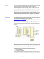
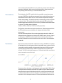
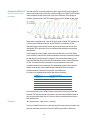
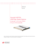
Agilent
U1051A Time to Digital Converter
Application Note - Absolute Time Recovery
Notices
© Agilent Technologies, Inc. 2012
No part of this manual may be reproduced in
any form or by any means (including
electronic storage and retrieval or
translation into a foreign language) without
prior agreement and written consent from
Agilent Technologies, Inc. as governed by
United States and international copyright
laws.
document that conflict with these terms, the
warranty terms in the separate agreement
shall control.
Safety Notices
Refer to the saftey notices included in the
specific product StartUp Guide or User
Manual.
Front and Rear Panel Symbols:
Manual Part Number
U1092-90055
Edition
The CE mark is a registered
trademark of the European
Community.
Edition 1.0, 24 July 2012
Printed in USA
Agilent Technologies, Inc.
Sales and Technical Support
To contact Agilent for sales and technical
support, refer to the “support” links on the
following Agilent web resources:
n
www.agilent.com/find/U1051A
(product-specific information and
support, software and documentation
updates)
n
www.agilent.com/find/cPCI
n
www.agilent.com/find/Assist
(worldwide contact information for
repair and service)
The C-Tick mark is a
registered trademark of the Australian
Spectrum Management Agency.
This symbol indicates
product compliance
with the Canadian Interference-Causing
Equipment Standard (ICES-001). It also
identifies the product is an Industrial
Scientific and Medical Group 1 Class A
product (CISPR 11, Clause 4).
This symbol indicates separate
collection for electrical and
electronic equipment, mandated
Warranty
under EU law as of August 13, 2005. All
The material contained in this document is
electric and electronic equipment are
provided “as is,” and is subject to being
required to be separated from normal waste
changed, without notice, in future editions.
for disposal (Reference WEEE Directive,
Further, to the maximum extent permitted by 2002/96/EC).
applicable law, Agilent disclaims all
warranties, either express or implied, with
This symbol on an instrument
regard to this manual and any information
means caution, risk of danger. You
contained herein, including but not limited to
should
refer
to the operating instructions
the implied warranties of merchantability
located
in
the
user documentation in all
and fitness for a particular purpose. Agilent
shall not be liable for errors or for incidental cases where the symbol is marked on the
or consequential damages in connection with instrument.
the furnishing, use, or performance of this
document or of any information
contained herein. Should Agilent and the
user have a separate written agreement with
warranty terms covering the material in this
This symbol indicates the time
period during which no hazardous
or toxic substance elements are
expected to leak or deteriorate during
normal use. Forty years is the expected
useful life of the product.
This symbol indicates the
instrument is sensitive to
electrostatic discharge (ESD).
ESD can damage the highly sensitive
components in your instrument. ESD damage
is most likely to occur as the module is being
installed or when cables are connected or
disconnected. Protect the circuits from ESD
damage by wearing a grounding strap that
provides a high resistance path to ground.
Alternatively, ground yourself to discharge
any built-up static charge by touching the
outer shell of any grounded instrument
chassis before touching the port connectors.
This symbol denotes a hot surface.
The side cover of the module will be
hot after use and should be allowed
to cool for several minutes.
Abstract
This document describes the methodology to utilize the Agilent (Acqiris) U1051A Time
to Digital Converter (TDC) module in applications requiring absolute time
measurements beyond the range of the module. The TDC module is a precise event
counter with 50 ps timing precision. The module, however, has a limitation in that the
counter circuitry in the module resets every 10.48 milliseconds (or more precisely
10.48576 ms). This poses a problem in applications requiring longer capture times
beyond this time window. This document, however, describes a method to allow users
to take advantage of the modules speed, precision, and channel count to extend the
capabilities to virtually any event time measurement application.
Background
For a detailed description of the theory of operation of the U1051A TDC module refer to
the User’s Manual for the module which may be obtained at
http://www.agilent.com/find/U1051A along with other documentation and resources
for this module.
Figure 1 (below) shows a simplified block diagram of the TDC module. The module
incorporates 6 input channels and a Common channel used for external trigger/start
operation.
Figure 1 - U1051A (TC890) Simplified block diagram
Measured events from the channels are stored into a dual-bank memory structure and
are read out upon a memory bank switch event. There are multiple methods of bank
switching the memory prior to system readout. This document will outline two
methodologies that can be utilized to perform a bank switch operation:
1. Memory-based Setting
2. Number of Common Events.
The key thing to note about the TDC module is that all events are stored in memory in
the order that they are received. Thus when events are time-tagged and subsequently
3
read out of the module, they will form an array of time tag events in order of their input
event time. Additionally, when an event is stored into memory, a flag is set for that
entry denoting which channel (1-6) is associated with the event.
The Limitation
The key limitation of the TDC module is that it is essentially a counter that resets to
zero every 10.48576 ms, thus all events measured by the module will have a time tag
event between 0 and 10.48576. This can cause confusion and problems for longer
duration measurements. For example, say that you are measuring a 3 ms clock period
on channel 1 of the TDC module and that you have started the TDC module with a
hardware trigger synchronized to your 3 ms clock. If you read the first 4 entries of data
on channel 1 you would obtain the following:
3.000 ms, 6.000 ms, 9.000 ms, 2.51424 ms (to 50 ps precision)
The first three values make sense but the fourth does not. What has happened is that
the TDC module has reset (or rolled back to 0) between the third and fourth
measurement.
This issue poses two problems. First, recovering the absolute time of the fourth and
subsequent events will require accounting for this 10.48576 ms roll. Second, if events
are infrequent (> 10.48576 ms) when we read out the event times there will be an
ambiguity of whether the event occurred in the next counter roll or some subsequent
counter roll.
The Solution
Figure 2 below shows how the TDC module resets to 0 every 10.48576 ms. To address
the ambiguity issue of ensuring that we have an event within every counter roll cycle, it
is necessary to provide a periodic clock event that is less than the 10.48 ms counter
roll period. We recommend using a 100 Hz clock signal into one of the TDC input
channels. The 100 Hz clock signal equates to a 10 ms period which will ensure that an
event is measured on every clock cycle.
Figure 2 - TDC counter cycle
For purposes of our discussion, we will assume the user has provided a 100 Hz (10 ms)
clock signal into the Channel 6 input of the TDC module. In Figure 3 below channel 6
events are shown in green. Notice that since the 10 ms clock event is less than (and
not fundamentally related to) the clock roll interval, that the CH6 events occur earlier
and earlier in each subsequent counter roll. The time period between CH6 events we
4
know will be 10 ms. This now becomes our absolute time clock counter event.
Eventually as shown on the right of Figure 3 (below), there will be times when two CH6
events are measured in the same counter roll cycle. This won’t pose a problem in
recovering absolute time.
Figure 3 - Channel 6 Events
Next, we will examine how to correct for absolute time for any and all events collected
regardless of when they occurred.
To aid implementation of software control of the TDC module, example programs are
provided by Agilent covering several different programming environments. These
example programs cover the basic control of the module including module setup and
reading of data. These examples and a Programmer’s Manual are available from
Agilent.com website. These basic examples can be easily augmented with software to
perform the absolute time recovery mentioned in this application note.
Acquisition Method 1
Memory-based bank switch
This method of TDC acquisition calls for the user to set the amount of memory used in
the acquisition. When the set number of events is written into memory, then the TDC
will switch memory banks to allow users to read out the data of the prior memory bank
and begin acquiring data into the second bank. This capability allows the TDC module
to continuously and seamlessly acquire data events indefinitely. (Note: Continuous and
gap-free operation will be maintained as long as events can be written out of the
memory bank prior to the TDC module bank-switching back to this memory. Refer to
the TDC module User Guide for rate transfer information).
In Figure 4 (below) we will look at an example measurement and how we can
implement a correction routine to deal with the counter rolls.
Figure 4 - Example measurement, events A - E
In this case we are looking at the first set of event data that was retrieved from the
5
module, and these initial events occurred right at the beginning of acquisition on the
first counter cycle. In this example we will look at 5 measured events (A through E) as
shown on the diagram above. The measured data might look like this:
Ch 1 Event - A
4.123 ms
Ch 2 Event - B
5.123 ms
Ch 6 Event - C
8.454 ms
Ch 1 Event - D
10.123 ms
Ch 2 Event - E
0.345 ms
Here we see that we have two measurement channel events (1 and 2) followed by a
CH6 (100 Hz clock) event followed by two additional channel events (1 and 2) and the
last event has occurred on the next counter roll cycle.
This acquisition was performed using a software trigger to start acquisition so that the
start time of acquisition (t=0) is independent of the CH6 clock. Events A through D all
occur on the first counter cycle and between events D and E, the TDC module has
rolled to the next counter cycle.
Next, we will examine how to process measurement data to recover the absolute
event time at any arbitrary point in the collected data.
In this example, we’re looking at arbitrary events collected by the TDC module. For this
process to work the user needs to collect and keep track of the following information.
1. The initial event time of the first CH6 clock entry
2. The number of CH6 events that have occurred
With these two pieces of information we can stitch together an accurate time axis for
the data. In the Figure 5 (below) we have another scattering of events.
Figure 5 - Example measurement, events Q - U
As we read events Q through U out of memory, they will be read out in this order:
Ch 1 Event - Q
4.123 ms
Ch 2 Event - R
5.123 ms
Ch 6 Event - S
8.454 ms
Ch 1 Event - T
10.123 ms
Ch 2 Event - U
0.345 ms
Here we see two channel events Q and R occurring on one given counter cycle
followed by a CH6 clock event on the same cycle then another CH1 event T on the
6
same cycle. Finally event U occurs on the following counter cycle. Just examining the
data you can see that a counter roll has occurred because Event U has a smaller value
than event T. Note also that up until Event S we had a stored CH6 count of 5 events
and after event S we now have a count of 6 CH6 events.
Recovering the absolute time of all events is now a two part process. First we need to
determine a Raw Absolute Time which equates to the most recent CH6 event time. To
do this we can use the following formula:
Formula 1
Raw Absolute Time = CH6Count × 10.48576 + CH6EventTime
So for events Q and R above, the CH6 count is 5. We would also have the first CH6
event time from our earlier data thus we can calculate the Raw Absolute time. For
event T we would have a CH6 count of 6 along with the event time of the first CH6
event to properly anchor the Raw Absolute Time (which matches the exact time at
Event S).
The Raw Absolute Time is merely the exact time of each CH6 time event. Next, we
need to account for the time difference from other channel measured events to the
previous CH6 absolute time. This is done with the following 2 formulas:
If (CHx_EventTime > MostRecentCH6EventTime) then we are on the same ramp
cycle, Then:
Formula 2a
Abs Event Time = RawAbsTime + CHx_EventTime − MostRecentCH6EventTime
Event T above meets this criterion. Its event time is greater than the most recent CH6
event time (since it is higher on the cycle). Therefore, to determine Event T’s absolute
time we take the Raw Absolute Time calculated earlier and add in the difference from
the current event T minus the last CH6 event time.
Next, if the event time for the channel is less than the most recent CH6 event time
then we use this formula:
If (CHx _EventTime < MostRecentCH6EventTime) then we are on the next ramp cycle
and we need to factor in the 10.48576 ms thus:
Formula 2b
Abs Event Time = RawAbsTime + 10.48576 ms − MostRecentCH6EventTime + CHx_EventTime
Event U above meets this criterion. It has a smaller value in time (relatively speaking)
than the Event time S so we know that a counter roll has occurred. Therefore, we need
to take the Raw Absolute Time (at Event S) and add in the full counter time of
10.48576 ms minus the most recent CH6 event time, and then we need to add in the
measured channel event time. This would provide the absolute time at Event U.
7
Acquisition Method 2
Number of common events
bank switch
This method of TDC acquisition calls for the user to apply the 100 Hz clock signal (10
ms) into the Common Input of the TDC module instead of one of CH6. The TDC module
is then configured to bank switch on N cycles of the COM input. This is simply an
alternate operating mode of the TDC module. Refer to Figure 6 (below) for this mode.
Figure 6 - Acquisition method 2
Notice that now the first pulse of the 100 Hz clock signal will begin TDC acquisition at
t=0. Every time a COM input fires (10 ms) the TDC time is reset back to 0. This
eliminates having to deal with the counter roll phenomenon because we are never
allowing the TDC to go beyond 10 ms. It also dramatically simplifies recovering the
absolute time.
In this example N is set to 5 which means that every 5th clock cycle of the 100 Hz
clock (or 50 ms in total) the TDC module will perform a memory bank switch and allow
the data from the previous bank to be read out. Thus memory bank switches occur
every 5th COM input (50 ms) while the TDC module time is reset on every COM input
(10 ms). This makes it easier to deal with reconstructing the time axis so this
acquisition method has this advantage. The disadvantage of this mode is that if the
number of events that come in within the time window (of 50 ms) exceeds the
maximum memory of the memory bank, then events will be lost.
Let’s look at our example above and the data that was collected:
COM Event - 1
0 ms (abs time 10 ms)
CH1 Event - A
5.458 ms
COM Event - 2
0 ms (abs time 20 ms)
CH2 Event - B
3.123 ms
COM Event - 3
0 ms (abs time 30 ms)
COM Event - 4
0 ms (abs time 40 ms)
COM Event - 5
0 ms (abs time 50 ms)
Here we see mostly a set of COM (Common) events that are read. Each COM input
resets the TDC time to 0 thus we only need to count the number of COM events that
have occurred and multiply it by our 10 ms to achieve our starting reference time or
Raw Absolute Time.
Formula 3
Raw Absolute Time = COM_Count × 10.000 ms
So for our example Event A has occurred after the 10 ms start point so we need to only
add in the measured event time for Event A (5.458 ms) and add it to 10 ms for an
8
absolute time of 15.458 ms for Event A. Again, the TDC time is reset to 0 for every
COM input, and our COM input rate is 10 ms (or less than the max value of 10.48576
ms) thus:
Formula 4
Abs Event Time = Raw Absolute Time + CHx_EventTime
9
T h e M o d u l ar T an g r am
The four-sided geometric symbol that appears in Agilent modular
product literature is called a tangram. The goal of this seven-piece
puzzle is to create shapes—from simple to complex. As with a
tangram, the possibilities may seem infinite as you begin to create
a new test system. With a set of clearly defined elements—
hardware, software—Agilent can help you create the system you
need, from simple to complex.
DISCOVER the Alternatives …
… Agilent MODULAR Products
Agilent Advantage Services is committed to your
success throughout your equipment's lifetime.
www.agilent.com/find/advantageservices
Agilent Email Updates keep you informed on the
latest product, support and application information.
www.agilent.com/find/emailupdates
Agilent Channel Partners provide sales and solutions
support. For details, see
www.agilent.com/find/channelpartners
ISO 9001:2008 certified. For details, see
www.agilent.com/quality
www.pxisa.org
www.axistandard.org
PICMG and the PICMG logo, CompactPCI and the CompactPCI logo,
AdvancedTCA and the AdvancedTCA logo are US registered trademarks of the
PCI Industrial Computers Manufacturers Group. “PCIe” and “PCI EXPRESS” are
registered trademarks and/or service marks of PC-SIG. Microsoft, Windows,
Visual Studio, Visual C++, Visual C#, and Visual Basic are either registered
trademark or trademarks of Microsoft Corporation.
Product descriptions in this document are subject to change without notice.
© Agilent Technologies, Inc. 2012
w w .ag i l e n t .c o m
w w w .ag i l e n t .c o m / fi n d / m o d u l ar
w w w .ag i l e n t .c o m / fi n d / e m b e d d e d
For more information on Agilent Technologies' products,
applications or services, please contact your local Agilent office.
(For additional listings, go to www.agilent.com/find/assist.)
Americas
Canada
Brazil
Mexico
United States
(877) 894 4414
(11) 4197 3500
01800 5064 800
(800) 829 4444
Asia Pacific
Australia
China
Hong Kong
India
Japan
Korea
Malaysia
Singapore
Taiwan
Thailand
1 800 629 485
800 810 0189
800 938 693
1 800 112 929
0120 (421) 345
080 769 0800
1 800 888 848
1 800 375 8100
0800 047 866
1 800 226 008
Europe & Middle East
Austria
Belgium
Denmark
Finland
France
Germany
Ireland
Israel
Italy
Netherlands
Spain
Sweden
Switzerland
United Kingdom
43 (0) 1 360 277 1571
32 (0) 2 404 93 40
45 70 13 15 15
358 (0) 10 855 2100
0825 010 700 (0.125 €/minute)
49 (0) 7031 464 6333
1890 924 204
972 3 9288 504 / 544
39 02 92 60 8484
31 (0) 20 547 2111
34 (91) 631 3300
0200 88 22 55
0800 80 53 53
44 (0) 118 9276201