1
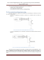
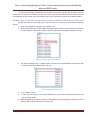
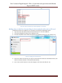
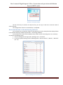
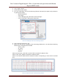
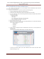
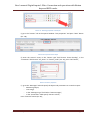
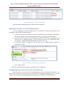
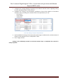
User’s manual. Digital inputs 1-Wire. Connection and operation with iButton keys and RFID-cards. Contents Necessary tools, devices, materials ................................................... Ошибка! Закладка не определена. General information ........................................................................... Ошибка! Закладка не определена. Readers connection and signal processing ................................................................................................... 4 Adding a key to the list of trusted keys in the terminal without a microSD-card ................................. 5 Adding a key to the list of trusted keys in the terminal with a microSD-card ...................................... 6 Data transmission to the monitoring software ..................................................................................... 7 Driver identification by means of iButton keys. ........................................................................................... 9 Signaling setting to work with iButton keys ................................................................................................12 Configuring the control of executive mechanisms .....................................................................................12 SPA “GalileoSky” LLC Page 1 User’s manual. Digital inputs 1-Wire. Connection and operation with iButton keys and RFID-cards. Necessary tools, devices, materials To connect the GalileoSky terminal (hereinafter – terminal) one should have: 1. Electrical tools. Picture 1 2. Set of connecting wires with fuses. Picture 2 3. Windows-based computer with the installed program of configuration of GalileoSky terminals – "Configurator" Picture 3 SPA “GalileoSky” LLC Page 2 User’s manual. Digital inputs 1-Wire. Connection and operation with iButton keys and RFID-cards. General information It is possible to connect different sensors and devices working via 1-Wire interface to the GalileoSky terminal, and their simultaneous work is supported. 1-Wire interface is bi-directional bus of communication for devices with low-speed data transmission in which data are transferred along the power-supply circuit, using only two wires - one for the negative power supply and the ground, and the second for the positive power supply and data (in some cases a separate power cord is used). The following devices can be used as 1-Wire sensors: 1. iButton key reader (Pic. 4) – a contact device for reading and data recording at the moment of contact with an iButton identification key (hereinafter – IK); Picture 4. iButton readers and keys 2. RFID-tags readers (Pic. 5) – a device working on the principle of the radio-frequency contactless identification. Allows you to read information from RFID tags using radio waves. Picture 5. RFID-tags and readers SPA “GalileoSky” LLC Page 3 User’s manual. Digital inputs 1-Wire. Connection and operation with iButton keys and RFID-cards. You can do the following with the help of iButton keys and RFID-tags: Configure driver or object identification; Control signaling enabling/disabling; Control different executive mechanisms enabling/disabling. Readers connection and signal processing To receive and process the signal from the iButton IK or the RFID-tag it is necessary to connect the readers to the terminal: Connection to GalileoSky v5 terminal is carried out in accordance with the scheme of Picture_6. Picture 6. Connection scheme of iButton (RFID) readers and v5 terminals Connection to GalileoSky v1.x, v2.x terminals is carried out in accordance with the scheme of Picture 7. Picture 7. Connection scheme of iButton (RFID) readers and v1.x; v2.x terminals Terminal processes the signal from the reader in accordance with an internal algorithm - at the time of IK applying to 1-Wire and GND contacts the number of the key is entered into the memory, a point is recorded and the four low-order bytes excluding checksum are sent to the server. At disconnection of the key there is the number zeroing, record of a point and sending the message to the server. SPA “GalileoSky” LLC Page 4 User’s manual. Digital inputs 1-Wire. Connection and operation with iButton keys and RFID-cards. To control the signaling trusted keys can be used. The trusted keys are the IKs stored into the memory of the terminal or saved to the micro-SD card. In the terminal without the micro-SD card up to 8 trusted keys can be stored; if you use the micro-SD card it is possible to specify up to 1000 trusted IK. Adding a key to the list of trusted keys in the terminal without a micro-SD card To add IK to the list of trusted keys in the terminal it is necessary to execute the following actions. 1. Start the Configurator and go to the “Device” tab. 2. Attach the iButton key to the 1-Wire and GND contacts and fix the value of the trusted key ID in the “iButton” field of the “Device” tab (this value will be displayed in brackets Pic. 8). Picture 8. Fixing the value of the iButton ID 3. Go to the “Settings” tab –> “Digital inputs” and enter the received above value in the “Key 1” field of the section “iButton keys” (Pic. 9). Picture 9. Entering iButton key ID 4. 5. Press “Apply” button. In case if you are going to use several iButton keys, you need to enter the keys IDs in the “Key 2… Key 8” fields. 6. When applying an IK with one of the set identifiers, the corresponding bit will be set in the "iButton Keys" field of the “Device” tab (Pic. 10). SPA “GalileoSky” LLC Page 5 User’s manual. Digital inputs 1-Wire. Connection and operation with iButton keys and RFID-cards. Picture 10. View of “iButton keys” field at applying of a trusted IK Adding a key to the list of trusted keys in the terminal with a micro-SD card To add IK to the list of trusted keys it is necessary to execute the following actions: 1. Eject the micro-SD card from the terminal and insert it into the computer; 2. Start the Configurator and go to the «iButton» tab; 3. From the dropdown menu select the disk that corresponds to the micro-SD card (Pic. 11); Picture 11. Adding the trusted keys IDs 4. Enter the numbers of the keys; the keys can be entered in decimal or hexadecimal form, the value in the other column is converted automatically; 5. Press "Save to disk" button to save the changes to the micro-SD card (Pic. 12). SPA “GalileoSky” LLC Page 6 User’s manual. Digital inputs 1-Wire. Connection and operation with iButton keys and RFID-cards. Picture 12. "Save to file" button The list of the keys is stored in the keys.bin file, you can copy it and use in micro-SD cards of other terminals. The configuration of the list of trusted keys is completed. Data transmission to the monitoring software Let’s consider the transmission of data on the iButton keys on the example of the display of data in the «Wialon Hosting» software (hereinafter – monitoring software). To send data on the work with the iButton keys readers to the monitoring server it is necessary to perform the following steps. 1. Start the Configurator and go to the “Settings” tab -> “Protocol”. 2. In the main packet settings tick the following fields: “Status of device”, “iButton”, “iButton2” (Pic. 13). Picture 13. Settings in the “Protocol” tab SPA “GalileoSky” LLC Page 7 User’s manual. Digital inputs 1-Wire. Connection and operation with iButton keys and RFID-cards. 3. Press “Apply” button. 4. Attach the IK to the reader. 5. Go to the “Messages” tab of the monitoring software and specify the object and parameters to generate the report: Monitoring object; Time range; In the “Message type” field select “Data messages”; In the “Parameters” field specify “Raw data”; Picture 14. “Messages” tab in the monitoring software 6. Press “Execute” button (Pic. 14). 7. Make sure that data are available in the monitoring software (Pic. 15). Data about attaching iButton keys are displayed in the fields: ibutton_code; avl_driver; trailer_id; ibuttons Values in the ibutton_code and avl_driver fields correspond to iButton value. Value in the trailer_id field corresponds to iButton2 value. Value in the ibuttons field shows the decimal number corresponding to a bit mask of attached keys. Picture 15. iButton key data of the monitoring software SPA “GalileoSky” LLC Page 8 User’s manual. Digital inputs 1-Wire. Connection and operation with iButton keys and RFID-cards. Driver identification by means of iButton keys. Let’s consider work with iButton IK on the example of driver identification mode and data displaying in the monitoring software. To check the identification it is necessary to perform the following steps: 1. Connect an iButton keys reader to the terminal (Pic. 7); 2. Simulate the driver identification mode by touching the key to the reader; 3. Go to the “Messages” tab in the monitoring software and specify the object and parameters to generate the report: Monitoring object; Time range; In the “Message type” field select “Data messages”; In the “Parameters” field specify “Raw data”; 4. Press “Execute” button (Pic. 14); 5. Make sure that data are available in the monitoring software (Pic. 15). Data about attaching iButton keys are displayed in the fields: ibutton_code; avl_driver; trailer_id; ibuttons 6. Create a sensor to display the status of identification of the driver, to do this perform the following steps: а) select the type of display «Monitoring» in the “Map” tab (Pic. 16); Picture 16. “Map” tab of the monitoring software b) select the necessary object, press “Open additional menu” button and select “Open properties dialog” (Pic. 17); SPA “GalileoSky” LLC Page 9 User’s manual. Digital inputs 1-Wire. Connection and operation with iButton keys and RFID-cards. Picture 17. Selecting properties of the object c) go to the “Sensors” tab in the opened window “Unit properties” and press “New” button (Pic. 18); Picture 18. Properties of the object d) enter the sensor’s name, in the “Sensor type” field choose “Driver binding”, in the “Parameter” field choose “avl_driver” or “ibutton_code” (Pic. 19), press “ОК” button; Picture 19. Sensor properties e) go to the “Messages” tab and specify the object and parameters to create the report: Monitoring object; Time range; In the “Messages type” field select “Data messages”; In the “Parameters” field specify “Sensors values”; Press “Execute” button (Pic.20); SPA “GalileoSky” LLC Page 10 User’s manual. Digital inputs 1-Wire. Connection and operation with iButton keys and RFID-cards. Picture 20. “Messages” tab f) set the display of the sensor with the name «Driver» in the table of values of the sensors (Pic. 21); Picture 21. Key identifier in the monitoring software g) check the key identifier display in the “Driver” column (Pic. 22); SPA “GalileoSky” LLC Page 11 User’s manual. Digital inputs 1-Wire. Connection and operation with iButton keys and RFID-cards. Picture 22. Key identifier in the monitoring software At that checking of identification of the driver mode is completed. Signaling setting to work with iButton keys To set the signaling to work with iButton keys it is necessary to connect the terminal to the Configurator and perform the following steps: 1. If necessary, add the key identifier to the list of trusted keys (this procedure is described in the section “Readers connection and signal processing” on pages 5-6 of this manual); 2. Define the event that occurs when the IK with a trusted ID is attached. To do this go to the “Settings” tab –> “Signaling settings”, select the necessary value in the “Use iButtons” field, for example, “enables signaling while holding trusted key” (Pic. 23); 3. In the fields “Phone 1… Phone 4» you can enter up to 4 mobile phone numbers for notification of alarm; Picture 23. “Signaling” tab setting to work with iButton IK 4. Press “Apply” button. At that the signaling setting to work with the iButton key is completed. Configuring the control of executive mechanisms Terminal allows you to control the starting/stopping of various executive mechanisms. The terminal has 4 outputs, for which you can set the reaction to changing of signaling status. To set the outputs of the terminal for starting/stopping the signaling you must perform the following steps. SPA “GalileoSky” LLC Page 12 User’s manual. Digital inputs 1-Wire. Connection and operation with iButton keys and RFID-cards. 1. Configure the starting/stopping of signaling in accordance with the section “Signaling setting to work with iButton keys” of this manual. 2. Configure the “Arming” and “Disarming” parameters of one of the outputs in accordance with your aim by selecting the necessary value of the parameter (Pic. 24): No reaction; Invert output; Feed pulses. Picture 24. Setting of “Output” field parameters 3. Specify additional settings of the output (the pulse length in milliseconds, and the number of pulses), if the response is set to “Feed pulses” value. 4. Press “Apply” button. Setting of the GalileoSky terminal to work with iButton keys is completed; the terminal is ready to operate. SPA “GalileoSky” LLC Page 13