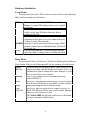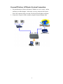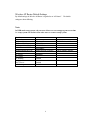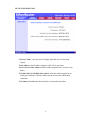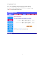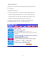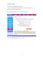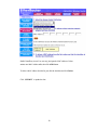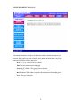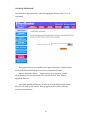
1
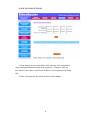
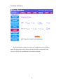
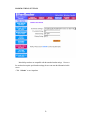
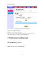
TEW-211BRP
Wireless AP Router
User’s Manual
Version 1.4
- Jan 2002
CONTENTS
Introduction .............................................................................3
Hardware Installation
..............................................................................5
General Wireless AP Router System Connection .........................6
Wireless AP Router Default Settings …………………………………7
Web Management Setttings ……….…………………………….8
Device Information ……..……………………………………………….10
Device Status ….………………………………………………………...10
Device IP Settings ….……………………………………………………12
Cable / ADSL ISP Settings ………………………………………………13
ISP Additional Settings …………………………………………………..14
Wireless Settings …………………………………………………………15
Modem Settings ………………………………………………………….16
Advanced Settings …………………………………………………………17
DHCP Server Settings ……………………………………………………17
Virtual Server Settings ……………………………………………………18
Access Control Settings …………………………………………………..19
Static Settings ……………… …………………………………………….22
Dynamic Settings …….…………………...………………………………23
Modem Settings……………………………………………………………24
Filter Settings ………………………………………………………………24
Administration Settings ……………………………………………………26
System Tools …………………………………………………………………27
Intruder Detection Log …………………………………………………….28
Display Routing Table ………………..……………………………………29
Load Settings ………….…………………………………………………...30
Upgrade Firmware ……...………………………………………………….31
Reset Device ……………………………………………………………….32
Troubleshooting ………………………………………………………………33
Technical Specifications ………………………….…………………………35
1
Introduction
Thank you for purchasing your TEW-211BRP Wireless AP Router
This manual will assist you with the installation procedure.
The package you have received should contain the following items:
??TEW-211BRP Wireless AP Router
??User’s Manual
??Power Adapter
Note: if anything is missing, please contact your vendor
2
Safety Notification
Your TEW-211BRP Wireless AP Router should be placed in a safe and secure location.
To ensure proper operation, please keep the unit away from water and other damaging
elements.
?
? Please read the installation guide thoroughly before you install the TEW-211BRP
Wireless AP Router
?
? The TEW-211BRP Wireless AP Router should only be repaired by authorized and
qualified personnel.
?
? Please do not try to open or repair the TEW-211BRP Wireless AP Router yourself.
?
? Do not place the TEW-211BRP Wireless AP Router in a damp or humid location,
i.e. a bathroom.
?
? The TEW-211BRP Wireless AP Router should be placed in a sheltered and
non-slip location within a temperature range of +5 to +40 Celsius degree.
?
? Please do not expose the TEW-211BRP Wireless AP Router to direct sunlight or
other heat sources. The housing and electronic components may be damaged by direct
sunlight or heat sources.
3
Hardware Installation
Front Panel
The front panel provides LED’s for device status. Refer to the following
table for the meaning of each feature.
PWR
Power status of the TEW-211BRP Wireless AP
Router. A steady LED indicates the power is applied
to the unit.
WLAN
The WLAN LED will be ON when AP function
enable, at this time Wireless clients are able to
connect to the AP.
WAN
Wide Area Network status. WAN LED is
illuminated when there is a good connection to the
10 BaseT mode Ethernet port.
MODEM Indicates console port Carrier Detect status. When
modem connection is established then LED should
be steady on.
STAT
System status indicator. A flickering light indicates
that when data is reading from or writing into flash.
Rear Panel
The rear panel features 4 LAN ports, WAN port, Modem port and Factory
Reset button. Refer to the following table for the meaning of each feature.
Power
Used to connect to the power outlet. Only use the power
(DC 5v)
adapter provided with the Wireless AP router. Use of an
unauthorized power adapter may cause damage to your
device and violate your warranty.
Modem
Port used to connect an external analog backup
modem/ISDN TA.
WAN
The RJ-45 Ethernet port labeled WAN is used to connect
your Wireless AP Router to your xDSL or Cable modem.
Reset
Resets the configuration to default settings.
LAN
The RJ-45 Ethernet ports used to connect your PC or
(1,2,3,4)
HUB, The Ethernet Cable used can be normal Ethernet
cables or even Crossover Cable.
The TEW-211BRP has internal AutoCrossover detection
circuit to automatic identify them.
4
General Wireless AP Router System Connection
1. The general function of Wireless AP Router is defined as an “AP + Router”, and the
connection is as follow diagram. In this mode, user may connect the WAN port to
Cable / DSL modem by using cross cable. The WAN LED will indicate connection.
2. Connect the LAN port to a hub or switch by using RJ-45 normal Ethernet cable.
5
Wireless AP Router Default Settings
By default settings, the Wireless AP Router is regarded as an “AP Router”. The default
settings are shown following.
Note:
In WEB mode setup system, only one user allows to access setup program at one time
i.e. setup system will decline when other users to connect setup system.
User Name
Password
AP Router Name
AP Router IP Address
AP Router Subnet Mask
10/100 Ethernet LAN IP
10 Mbps Ethernet WAN IP
WAN DHCP Client
RF ESSID
RF Channel
RF Roaming
Encryption
DHCP Server
NAT Routing
admin
Wireless AP
192.168.2.1
255.255.255.0
192.168.2.1
Obtain from ISP via DHCP
Enabled
Wireless
6
Enabled
Disabled
Enabled
Enabled
6
SOHO Wireless LAN
Can be manually configure
After 20 sec. Go to blank
Web Management Settings
TURN ON POWER SUPPLY
Quick power cycle can caused system corruption. When power on, be careful not to shut
down in about 5 seconds, because data is writing to the flash.
START -UP & LOG IN
In order to configure the Wireless AP Router, you must use your web browser and
manually input 192.168.2.1 into the Address box and press Enter. The Main Page will
appear.
In order to configure the Wireless AP Router, you must input the user-name into the
User Name box. Enter the password into the Password box and press the OK button. The
default User Name is “admin”. There is no default password, leave the Password field
blank.
Once you have logged-in as administrator, it is a good idea to change the
administrator password to ensure a secure connection to the Wireless AP Router. The
Advanced Settings section described later in this manual describes how to change the
password.
Once you have input the correct password and logged-in, the screen will change to the
Main Page screen.
7
MAKE CORRECT NETWORK SETTINGS OF YOUR COMPUTER
To change the configuration, use Internet Explorer (IE) or Netscape Communicator to
connect the WEB management 192.168.2.1.
SETUP WIZARD
Click SETUP WIZARD. Here allow user to configure basic network settings with your ISP
provider.
8
DEVICE INFORMATION
The Device Name is the same as the Computer Name that was set in the Setup
Wizard.
The IP Address is the IP Address assigned to LAN side of your Router.
The Private LAN Mac Address the Mac Address assigned to the LAN side of your
Router.
The Public WAN (Cable/DSL) Mac Address is the Mac Address assigned to the
WAN port of the Router. This Mac Address may be used by some cable modem
connections.
The Firmware Version is the current firmware version used by the Router.
9
DEVICE STATUS
The Device Status screen displays a graphical representation of your current
configuration. The left side of the screen shows your connection information in regards to
WAN and LAN IP Address information. The right side displays the connection status of
each device.
This means that there is a connection.
This means that there is not a connection.
The DHCP Log displays information about each IP Address assigned to a computer
using the DHCP server built-in to the Router.
10
DEVICE IP SETTINGS
It’s the LAN network domain settings. The default value is listed as following.
(IP Address: 192.168.2.1, IP Subnet Mask: 255.255.255.0) After changing the settings,
click NEXT to continue other network settings.
11
CABLE/xDSL ISP SETTINGS:
Here are the cable/ADSL ISP settings i.e. WAN port network settings.
By default, the WAN port is set to automatically obtain an IP address from your ISP, if ISP
provides DHCP server function.
To assign static IP for the WAN port, place a checkmark and enter the settings.
After changing the settings, click NEXT to continue other network settings.
12
ISP ADDITIONAL SETTINGS:
To set extra ISP settings, user may set the authentication data here while entering ISP. Here
also allow user to set the “idle time”, ”host and domain name” and ”WAN Ethernet MAC
address”. After changing the settings, click NEXT to continue other network settings.
DSL users:
If you are using a PPPoE client to connect to your DSL provider, then place a checkmark
on the first box, and enter the user name and password in the appropriate box.
Cable modem users:
If you are using a cable modem, then place a checkmark on the second box and enter the
host and domain name given by your cable provider.
13
WIRELESS SETTINGS
Here allow user to set Wireless AP Router IP and operation channel. The default value for
RF are as followed:
1. ESSID: Wireless, Channel: 6.
2. The encryption panel allows the entry of four keys for 64-bit encryption and one set of
128-bit key according to WEP function select. To be written to the driver and registry,
each key must consists of hex digits, which means that only digit 0-9 and letters A-F are
valid entries. If entered incorrectly program will not write keys to a driver.
3.Country domain selection, allow user to select channel option for different country.
4.After changing the setting, click NEXT to save and restart the system.
14
MODEM SETTINGS
Here allow user to set MODEM function settings.
If you are using a dial-up modem with the wireless router, place a checkmark in the box
and enter the settings for the dial-up connection.
After changing the setting, click NEXT to save and restart the system.
Click on the Save & Restart button to save your settings.
15
ADVENCED SETTINGS
Click ADVENCED SETTINGS. Here allow user to set the advanced settings as main
menu list.
DHCP SERVER SETTINGS
By default, the Wireless Router has DHCP server enabled to assign an IP address ranging
from 192.168.2.2 to 192.168.2.100. In addition, the router is capable of reserving up to
four sets of IP addresses within the local network for mail, web, or ftp server.
After changing the setting, clicks SUBMIT to change the configuration.
16
VIRTUAL SERVER SETTINGS
Here allow user to set several kinds of virtual service of the Wireless AP Router such as
HTTP, SMTP, POP3, FTP, TELNET services. After enter the settings, clicks SUBMIT to
save input data.
Specific application support is enabled in Virtual Server Settings under Advanced
Settings. The Wireless AP (Router) will detect and automatically open outgoing ports
required by most applications and games. However, some games and applications such as
Net meeting will require that the computer be exposed in the DMZ zone to allow incoming
ports required by the application. Click on the “Submit” button to save your settings.
17
DMZ
The Virtual Server Settings under Advanced Settings also enables one computer to
have full access to the Internet without the protection of the firewall. This allows a
computer to be exposed to unrestricted two-way communication outside of your network.
To enable DMZ, simply reserve an IP address for DMZ zone.
Click the “Submit” button to save your changes.
Only one computer can use DMZ at a time. Please note that enabling DMZ removes
the protection of the firewall, which exposes the computer to intrusion.
Use DMZ only when needed and not for extended periods of time.
Note: Service Port Range : (For Administrator only ) From 1~ 65535.
18
ACCESS CONTROL SETTINGS
This function allow administrator to have access control by enter MAC address of
client stations.
19
Enable Grant/Deny Access List, user may just input the MAC address of client
stations onto MAC Address table, then click ADD button.
To delete a MAC address from the list, just click the checkbox and click Delete .
Click ‘ SUBMIT ’ to update the data .
20
STATIC ROUTING SETTINGS
In Static Routing, the user has the ability to add a static route to the routing table by
simple entering the destination IP, subnet mask, and gateway. Clicking on “Add” and
then “Submit” which requires a restart for the IP address to be incorporated into the routing
table.
To delete a file from the list, just click the checkbox and click Delete .
21
DYNAMIC SETTINGS
By default, the Router will not send or receive any routing Internet protocols (RIP) to
update the routing table. However, the user can enable the Router to automatically send
and receive RIP packets to establish routes for commonly used paths.
22
MODEM STRING SETTINGS
Most dial-up modems are compatible with the standard modem strings. However
for modems that require special modem strings, the user can enter the information in this
screen.
Click ‘ Submit ’ to save input data.
23
FILTER SETTINGS
This page is only for MIS administrator only.
Enable LAN Site Filter function: Block / Pass.
Here allow user to add IP Address Range and Destination Port Range to LAN Side Filter
Table. The router will Block/Pass packet according to allocate IP range.
Click ADD button after input data. Click SUBMITS to update data.
To delete a file from the list, just click the checkbox and click Delete .
WAN FILTER SETTINGS: same as above.
Note: Port range ( from 1~65535 ) for administrator only.
24
ADMINISTRATION SETTINGS
Here allow user to change the password to execute setup system, user may also input the IP
address of Remote administration host in order to do the IP remote from Wan.
After changing the setting, clicks SUBMIT.
25
SYSTEM TOOLS
The System Tools section enables you to manage your Wireless AP Router and view
information related to unit functions. The following functions are described in this chapter.
Intruder Detection Log: View detection logs.
Display Routing Table : Display the routing status of the Router.
System Diagnostics: Display current status and connection information.
Save Settings: Save router configuration to a file .
Load Settings: Restore settings to factory default or from a saved file.
Upgrade Firmware : Upgrade the firmware with a latest version.
Reset Device : Reboot the Wireless AP Router.
26
INTRUDER DETECTION LOG
The Intruder Detection Log displays all information related to intrusion attempts on your
network. If any packets are seen as harmful, those packets are blocked and a log is kept
about the information related to that packet.
Index: (1,2,3 etc.) Refers to the row number.
Time : The time that the action was logged.
Protocol: (IP, UDP etc.) The type of protocol detected.
Source IP (Port): The source IP address of the intruding packet.
Dest IP (Port): The IP address assigned to the destination of the intruding packet.
Event: The type of intrusion.
27
DISPLAY ROUTING TABLE
The Display Routing Table screen displays the routing status that the Router is using. A
router uses a routing table to keep track of what IP addresses there are and where the router
should forward packets when it receives them.
Type : The type of routing protocol used.
Destination LAN IP Address: Shows the Destination IP Address on the LAN side.
Subnet Mask: Shows the subnet mask assigned to the Destination LAN IP Address.
Gateway IP Address: The IP Address of the assigned Gateway.
Hop Count: The number of hops between the Destination LAN IP Address and the
Gateway IP Address.
SAVE SETTINGS
Save the router’s current configurations to a file.
Click on SAVE button, click Save at “File Download” dialogue, enter the desired file
name with CFG as extension (i.e. SETUP.CFG) and choose the location (i.e.
C:\router), then click on Save . The configuration is now saved to the desired location.
28
LOAD SETTINGS
The Load Default Settings screen enables you to restore the settings that came as default.
Click on LOAD DEFAULT SETTINGS button on the left hand side menu, click Start,
and click Ok to load the default settings. Performing this task will replace all current
settings with default settings.
Load Settings from File allows user to load a saved configuration file to router. Click on
LOAD SETTINGS FROM FILE button on the left hand side menu, type in the file
location or click Browse to select the file location, and click Start button to load the
configuration.
29
UPGRADE FIRMWARE
Here allow user to upgrade firmware. After choosing upgrade firmware, click START to
load settings.
The Upgrade Firmware screen enables you to update the firmware. Updated firmware
usually fix problems encountered by users, but may incorporate new features.
Begin by clicking the “Browse…” button to browse your computer to select the
updated firmware file. Once the firmware file is selected, click the “Start” button to
upgrade the firmware.
Note: When upgrading the firmware, do not try to access the Internet and do not turn
the power off. Doing so may cause the firmware upgrade process to abort, which may
result in a corrupt firmware.
30
RESET DEVICE
The Reset Device screen enables you to reboot the Wireless AP Router. If any changes are
made and you want them to take effect, you will need to reset the Wireless AP Router to do
so. Click the “Start ” button to reset the Wireless AP Router.
Click the “Cancel” button to cancel.
31
Troubleshooting
Basic Functions
My Wireless AP Router will not turn on. No LED’s light up.
Cause:
?
? The power is not connected.
Resolution:
?
? Connect the power adapter to your Wireless AP Router and plug it into the power
outlet.
Note: Only use the power adapter provided with your Wireless AP Router. Using any other
adapter may damage your Wireless AP Router.
LAN Connection Problems
I can’t access my Wireless AP Router.
Cause:
?
? The unit is not powered on.
?
? There is not a network connection.
?
? The computer you are using does not have a compatible IP Address.
Resolution:
?
? Make sure your Wireless AP Router is powered on.
?
? Use the WINIPCFG utility described in the appendix to make sure that your computer
has a compatible IP Address. If your IP Address is not set correctly and you are using
DHCP, use WINIPCFG to renew your IP Address. Otherwise, make correct changes to
your Windows network settings. Make sure that the IP Address used on your computer
is set to the same subnet as the Router. For example, if the Router is set to 192.168.2.1,
change the IP address of your computer to 192.168.2.15 or another unique IP Address
that corresponds to the 192.168.2.X subnet.
Use the Reset button located on the front of your Router to revert to the
default settings.
32
I can’t connect to other computers on my LAN.
Cause:
?
? The IP Addresses of the computers are not set correctly.
?
? Network cables are not connected properly.
?
? Windows network settings are not set correctly.
Resolution:
?
? Make sure that each computer has a unique IP Address. If using DHCP through the
Wireless AP Router, makes sure that each computer is set to “Obtain an IP Address
automatically” and restart the computer. Use the WINIPCFG and PING utilities
described in the appendix to make sure that you can connect to each computer.
?
? Make sure that the Link LED is on. If it is not, try a different network cable.
?
? Check each computer for correct network settings.
ISP Connection Problems
I can access the Wireless AP Router, but I can’t connect to my
ISP.
Cause:
?
? Your DSL or Cable modem is not functioning correctly.
?
? The cable is connected from the WAN port of the Wireless AP Router to your DSL or
Cable modem.
?
? The wrong connection type is used in Setup.
?
? The username and password is not input correctly.
Resolution:
?
? Make sure that your DSL or Cable modem is running correctly and connected to the
WAN port of the Broadband Router.
?
? Make sure that the right connection type is used in the web configuration.
?
? Make sure that the username and password used in the connection type is correct.
?
? Some ISP's do not care if you share your broadband connection among multiple users.
Other ISP's will explicitly restrict this type of activity in your service contract. It is
important that you verify that you are in accordance with your service agreement
before sharing Internet access.
33
Wireless Troubleshooting
I can’t access the Wireless AP Router from a wireless network card
Cause:
?
? Settings are not the same among each wireless adapter.
?
? Out of range.
?
? IP Address is not set correctly.
Resolution:
?
? Make sure that the Mode, SSID, Channel and encryption settings are set the same on
each wireless adapter.
?
? Make sure that your computer is within range and free from any strong electrical
devices that may cause interference.
?
? Check your IP Address to make sure that it is compatible with the Wireless AP Router.
Performing a Factory Reset
Follow these steps to perform a Factory Reset using the Reset button on the back of
the Wireless AP Router.
1.
With the unit on, press and hold the Reset button with a pen or paper clip.
2.
Hold the reset button for about 5 or 6 seconds until the Power/Test LED on the
front panel blinks very quickly and then release.
3.
Wait a few seconds for the Broadband Router to reboot using default settings.
A Factory Reset can also be performed through the web configuration interface. Follow
these steps to perform a factory reset using the web configuration interface.
1.
Log-in to the Wireless AP Router web configuration interface.
2.
Click on the System Management link at the bottom of the screen.
3.
Click on Restore Default Settings.
4.
You will be asked if you want to restore to default settings. Click OK to restore
settings to default configuration or click Cancel to discard any changes.
34
Technical Specifications
Standards:
IEEE 802.3 10BASE-T Ethernet
IEEE 802.3u 100BASE-TX Fast Ethernet
ANSI/IEEE 802.3 NWay auto-negotiation
Protocols Supported:
TCP
IP
NAT
UDP
PPPoE
DHCP (Client and Server)
Management:
Web-Based
Ports:
LAN: NWay 10BASE-T/100BASE-TX Fast Ethernet
WAN: 10BASE-T
RS-232 (DB-9) Serial
TEW-211BRP Wireless AP Router Specifications
General Wireless Specifications:
IEEE 802.11b Wireless LAN, Wi-Fi Compatible
Access Point Frequency Band:
2.4 ~ 2.4835 GHz (subject to local regulation)
Access Point Number of Channel:
USA & Canada: 11 (1- 11)
Access Point Frequency Range:
5 Mbps
Access Point Data Rate:
11 Mbps
5.5 Mbps
2 Mbps
1 Mbps
35
Data encryption:
64/128-bit WEP and ESSID for Security
LED:
Power : Indicate power is ON
Status : Indicate Firmware loading under proceeding
WAN : Indicate WAN port connection
LAN : Indicate LAN port TX/RX operation
WLAN: Indicate Wireless been connected and operation
Power Specifications :
DC power supply
Input: DC 100-240, 50-60 Hz, 1A
Output: 5V DC, 2A converter incl.
Physical Dimensions
195mm(L) * 160mm (W) * 27mm (H)
Weight :
680 gram
(without power adaptor )
36