1
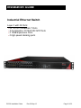
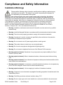
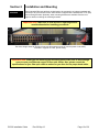
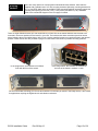
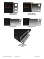
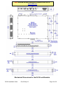
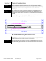
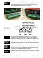
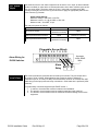
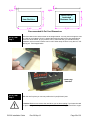
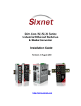
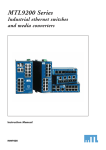
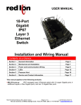
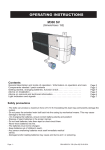
EL326 Industrial Ethernet Managed Switch Installation Guide Revision: 26 September 2013 www.redlion.net This page intentionally left blank. EL326 Installation Guide Rev 26-Sep-13 Page 2 of 32 Management Guide Installation Guide Industrial Ethernet Switch Layer 3 with 26 Ports: 20 10/100/1000BASE-T Ports 4 Combination 10/100/1000 SFP Ports 2 10GB Expansion Ports 2 high-speed stacking ports EL326 Installation Guide Rev 26-Sep-13 Page 3 of 32 About This Guide Purpose This guide gives specific information on how to properly install and maintain the switch. Audience The guide is intended for use by network administrators who are responsible for installing and setting up network equipment; consequently, it assumes a basic working knowledge of electrical safety and any local, regulatory or corporate rules for the installation of industrial electrical equipment. Conventions The following conventions are used throughout this guide to show information: Note or Notice: Emphasizes important information or calls your attention to related features or instructions. Caution, risk of danger: Alerts you to a potential hazard that could cause loss of data, or damage the system or equipment. Documentation must be consulted in all cases where this symbol is marked. Typical caution symbol. Warning, risk of electrical shock: Alerts you to a potential hazard that could cause personal injury. Typical warning symbol. Related Publications The following publication details the software features of the switch, including the Web interface, CLI and much more: EL326 Management Guide Also, as part of the switch’s software, there is an online web-based help that describes all management related features. Revision History First release. Copyright & Trademarks Copyright 2012 Sixnet, Inc.. All Rights Reserved. Note: All information in this document is subject to change without notice. EL326 Installation Guide Rev 26-Sep-13 Page 4 of 32 Compliance and Safety Information Installation Warnings Please read the following safety information carefully before installing or performing any maintenance on the switch. The safety of any system incorporating this equipment is the responsibility of the assembler of the system. Warning: These products should not be used to replace proper safety interlocking. No softwarebased device (or any other solid-state device) should ever be designed to be responsible for the maintenance of consequential equipment or personnel safety. In particular, Red Lion disclaims any responsibility for damages, either direct or consequential, that result from the use of this equipment in any application. All power, input and output (I/O) wiring must be in accordance with Class I, Division 2 wiring methods and/or in accordance with the authority having jurisdiction. Refer to section 1 for other important installation warnings. This equipment is suitable for use in Class I, Division 2, Groups A, B, C, D or non-hazardous locations only. Warning: Installation, maintenance and removal of the switch must be carried out by qualified personnel only. Warning: Install the Managed Switches in accordance with local and national electrical codes. Warning: The unit must be properly grounded to comply with international standards. Warning: If equipment is used in a manner not specified by the manufacturer, the protection provided by the equipment may be impaired. Warning: Do not connect to an AC power supply without an earth ground. Warning: This product does not contain any user serviceable parts. Warning: Do not work on equipment during periods of lightning activity. Warning: Do not connect a telephone line into one of the Ethernet RJ45 connectors. Warning (explosion hazard): Substitution of any components may impair suitability for Class I, Division 2 (Zone 2) areas. Warning (explosion hazard): When in hazardous locations, disconnect power before servicing units. Warning (explosion hazard): Do not disconnect equipment unless power has been switched off or area is known to be nonhazardous. Warning (explosion hazard): In hazardous or potentially hazardous locations, do not separate any part of unit when energized. Use the unit for internal connections only. Warning (explosion hazard): No hot swapping of modules in Hazardous Locations. Warning: Exposure to some chemicals may degrade the sealing properties of materials used in the Sealed Relay Device. Warning: Field Wiring conductor minimum insulation rating -75°C. Warning: Device is open-type and is to be installed in an enclosure suitable for the environment. EL326 Installation Guide Rev 26-Sep-13 Page 5 of 32 Fiber Optic Safety Warning: When using fiber optic ports, never look at the transmit laser, fiber TX port or fiber cable ends while the switch is powered on. It is highly recommended to keep the rubber fiber plugs inserted when the fiber port is not being used. Hi-Pot (Dielectric) Testing Caution: This device is designed to withstand a high-potential “hi-pot” (dielectric) test up to 2000 VAC or 2800 VDC (1 minute), or 2400 VAC or 3300 VDC (1 second) according to IEEE 1613. However, the surge circuitry must be bypassed before performing this test. See section 8 for details. Power Markings Direct Current (DC) Alternating Current Protective Conductor Terminal FCC Statement This device complies with Part 15 of the FCC Rules. Operation is subject to the following two conditions: This device may not cause harmful interference. This device must accept any interference received, including interference that may cause undesired operation. Warning: This equipment has been tested and found to comply with the limits for digital device, pursuant to Part 15 of the FCC Rules. These limits are designed to provide reasonable protection. This equipment generates, uses and can radiate radio frequency energy and, if not installed and used in accordance with the instructions, may cause interference to radio communications. However, there is no guarantee that interference will not occur in a particular installation. If this equipment does cause harmful interference to radio or television reception, which can be determined by turning the equipment off and on, the user is encouraged to try to correct the interference by one or more of the following measures: Reorient or relocate the receiving antenna. Increase the separation between the equipment and receiver. Connect the equipment into an outlet on a circuit different from that to which the receiver is connected. Consult the dealer or an experienced radio/TV technician for help. Notice: Shielded interface cable must be used in order to comply with emission limits. Notice: Changes or modification not expressly approved by the party responsible for compliance could void the user’s authority to operate the equipment. Industry Canada Statement EL326 Installation Guide Rev 26-Sep-13 Page 6 of 32 This device complies with the limits of Industry Canada per ICES-003. Operation is subject to the following two conditions: This device may not cause harmful interference, and This device must accept any interference received, including interference that may cause undesired operation. ce dispositif peut ne pas causer l'interférence nocive, et ce dispositif doit accepter n'importe quelle interférence reçue, y compris l'interférence qui peut causer l'opération peu désirée. EL326 Installation Guide Rev 26-Sep-13 Page 7 of 32 Warranty Statement Red Lion, manufacturer of Red Lion products, warrants to Buyer that products, except software, manufactured by Red Lion will be free from defects in material and workmanship. Red Lion's obligation under this warranty will be limited to repairing or replacing, at Red Lion's option, the defective parts within one year of the date of installation, or within 60 months of the date of shipment from the point of manufacture, whichever is sooner. Products may be returned by Buyer only after permission has been obtained from Red Lion. Buyer will prepay all freight charges to return any products to the repair facility designated by Red Lion. This limited warranty does not cover losses or damages which occur in shipment to or from Buyer or due to improper installation, maintenance, misuse, neglect or any cause other than ordinary commercial or industrial applications. In particular, Red Lion makes no warranties whatsoever with respect to implied warranties of merchantability or fitness for any particular purpose. All such warranties are hereby expressly disclaimed. No oral or written information or advice given by Red Lion or Red Lion’s representative shall create a warranty or in any way increase the scope of this warranty. This limited warranty is in lieu of all other warranties whether oral or written, expressed or implied. Red Lion's liability shall not exceed the price of the individual units, which are the basis of the claim. In no event shall Red Lion be liable for any loss of profits, loss of use of facilities or equipment, or other indirect, incidental or consequential damages. Note: The EL326 switches have no user serviceable parts. Any unauthorized service will void all warranties. In the unfortunate event that service is required please contact Red Lion for further instructions. Getting Support For local support please contact your regional Red Lion office. Otherwise, to get product information or contact Red Lion directly: Latest product info: www.redlion.net E-mail: [email protected] Phone: 1-877-406-9908 Fax: 1-518-877-8346 Mailing address: Red Lion Controls • 20 Willow Springs Circle • York • PA • 17406 • USA Products Covered This manual applies to the following products: EL326 26-port managed layer 3 industrial Ethernet rack-mount switch EL326 Installation Guide Rev 26-Sep-13 Page 8 of 32 Contents Section 1 General Information Page 9 Section 2 Installation and Mounting Page 11 Section 3 Thermal Considerations Page 15 Section 4 Power Wiring Page 16 Section 5 Communication Wiring Page 20 Section 6 LED Indicators Page 24 Section 7 Technical Specifications Page 26 Section 8 Hi-Pot Testing Page 28 Section 9 Service Information Page 30 EL326 Installation Guide Rev 26-Sep-13 Page 9 of 32 Section 1 Overview General Information The Red Lion EL326 is a 26 port industrial Ethernet managed switch designed to meet the extreme requirements of power substations, traffic control, railway and other harsh environments. It combines the high performance and security of an enterprise-class switch with rugged packaging and protected circuitry to meet the needs of the most demanding applications. This manual will help you install and maintain these industrial Ethernet switches. Installation of these switches is very easy and they will begin to operate as soon as they are powered up. Though these are fully managed switches, they will act as unmanaged until they are configured otherwise. Refer to the separate software manual or management guide for configuration of the advanced networking functionality and security. Note: This manual only covers the installation and wiring of these switches. Refer to the separate Management Guide for details on configuring and using any of the management functions such as SNMP, RSTP, IGMP, VLANs, security, port mirroring and much more. Basic Operation Unlike an Ethernet hub that broadcasts all messages out all ports, these industrial Ethernet switches will intelligently route Ethernet messages only out the appropriate port. The major benefits of this are increased bandwidth and speed, reduction or elimination of message collisions, and deterministic performance when tied with real-time systems. These industrial Ethernet switches support 10BaseT (10 Mbps), 100BaseT (100 Mbps) and 1000BaseT (1000Mbps) on the first 24 ports via standard RJ45 connectors. These ports will independently auto-sense the speed/duplex and mdi/mdix-crossover allowing you to use straight or crossed-wired cables. Ports 21-24 are combination ports and also provide SFP cages that accept industry-standard pluggable SFP transceivers of various types including multimode, singlemode, long-haul, bidi and more. These pluggable SFP ports support 100/1000BaseF (100/1000 Mbps) noise-immune fiber connections up to 120km. General Specifications These general specifications apply to these industrial Ethernet switches. Refer to Section 7 for complete technical specifications. Number of ports Ethernet Switch Type Ethernet Switch Mode Ethernet Protocols Ports 1 through 20 Ports 21 and 24 RJ45 Ports Operation Fiber Optic Type Package style 26 Ethernet ports Managed Store and forward, wire-speed, non-blocking All standard IEEE 802.3 protocols supported Gigabit RJ45 ports for 10/100/1000 Mbps connections Gigabit SFP slots with both RJ45 (10/100/1000) or 100 or 1000 Mbps fiber transceivers Auto-negotiation, auto-mdi/mdix-crossover and auto-polarity Multimode, singlemode, long-haul or special application 1U 19” rack mount Cleaning: Equipment can be wiped down with a damp cloth. EL326 Installation Guide Rev 26-Sep-13 Page 10 of 32 Compliances These industrial Ethernet Switches meet the following standards plus others: Sixnet, LLC is an ISO9001:2008 certified company (FM 65232) since 1996. These devices are designed, developed and manufactured per an ISO9001 quality management system. Electrical safety These devices have been designed to meet the basic safety requirements of the following standards: CE per Low Voltage Directive and IEC 61010-1 UL508 (Industrial control equipment), ANSI / ISA12.12.01 (Hazardous Locations) CSA C22.2 No. 142 and No. 213 (per cUL) EMC (emissions and immunity) CE per the EMC directive IEC 61000-6-2: Immunity in industrial environments IEC 61000-6-4: Emissions in industrial environments FCC part 15 and ICES 003. See FCC statement on page 6. EN 55022 (CISPR22) WEEE compliance These devices comply with the WEEE directive. Do not throw away these devices in the standard trash. Contact Red Lion regarding proper disposal. RoHS compliance These devices comply with the RoHS directive and are considered lead and other hazardous substance free. EL326 Installation Guide Rev 26-Sep-13 Page 11 of 32 Section 2 Overview Installation and Mounting These industrial Ethernet switches are designed to be mounted in an industry standard rack or directly to any flat surface indoors. Each switch is supplied with a standard set of 19” (EIA) rack mounting brackets. Optionally, other mounting brackets are available. See the next page for details on utilizing the mounting brackets. Important Note: Make sure to read Section 3 regarding thermal considerations before installing your switch. The above image shows an EL326 in front style arrangement (ports in front and power in the back) mounted in a typical 19” rack, prior to wiring. Important Note: When you are choosing your mounting option make sure to allow enough room to route your Ethernet copper or fiber optic cables. Also, please consult the specifications for your fiber optic cable to make sure you allow for the proper bend radius. EL326 Installation Guide Rev 26-Sep-13 Page 12 of 32 Mounting Brackets There are many options for mounting these industrial Ethernet switches. Each switch is supplied with a standard set of 19” rack mounting brackets. Optionally, mounting brackets for 23”, 24” and ETSI width racks are available. These mounting brackets universally support the mounting hole spacing per the EIA (1.25”), ETSI (25mm) and WECO (1.00”) standards. Refer to the mechanical diagram on the next page for details. There are eight threaded inserts (see red arrows above) on each side of the switch that allow the brackets to be mounted in numerous positions for the best fit in your rack. The brackets also have extra holes (see blue arrows above) allowing them to be shifted right or left 1/2 inch. Use the supplied screws to mount the bracket in the desired position. Plastic screws are also provided to plug the unused holes. See below for possible mounting positions. In the image above, the brackets are mounted flush with the front of the switch. In the image above, the brackets are mounted so the front of the switch is setback 1/2 inch. For the most durable mounting you can use two brackets on each side (as shown in the image above). This is ideal for applications requiring the highest shock and vibration resistance. EL326 Installation Guide Rev 26-Sep-13 Page 13 of 32 Standard 19” bracket Part #: EK1-BRCKT-19 (set of 2) Optional ETSI bracket Part #: EK1-BRCKT-ETSI (set of 2) Optional 23” bracket Part #: EK1-BRCKT-23 (set of 2) Optional 23/24” bracket Part #: EK1-BRCKT-2324 (set of 2) Optional wall bracket Part #: EK1-BRCKT-WALL (set of 2) EL326 Installation Guide Rev 26-Sep-13 Page 14 of 32 Note: AutoCAD and other drawings are available on the CD or at: www.redlion.net Mechanical Dimensions for the EL326 and Brackets EL326 Installation Guide Rev 26-Sep-13 Page 15 of 32 Section 3 Thermal Considerations Overview The EL326 switches are designed to operate from -35 to +80˚C when they are installed properly. The switch is cooled via conduction and radiation. There are no fans. Instead there are various heat-sinks inside the switch to conduct the heat from the components to the heavygauge aluminum case. The heat is then dissipated from the case via radiation to the surrounding air. Rack Mounting When the switch is rack mounted, for best heat dissipation it is recommended that there be around 1/2U or more of free air space above and below the switch (as shown below). This allows the heat to radiate to the air. Any moving air in your rack will improve on the cooling of the switch. Note: An air gap is not absolutely necessary but highly recommended when you know that the switch will experience high heat (> 60˚C) for extended periods of time. other device 0.75" [19.1mm] above switch 0.75" [19.1mm] below switch other device EL326 Rack Mounting Recommendation Suggestion: If your space is limited and you must choose between an air gap on the bottom versus an air gap on the top it is better to have the air gap on the top. BTU / Hour The power consumption of the switch can be as much as 120 Watts with all ports linked and active. Based on this, the heat dissipation can be as much as 408 BTU per hour. Please plan your system accordingly. EL326 Installation Guide Rev 26-Sep-13 Page 16 of 32 Section 4 Power and Output Wiring Warning: Please read this section fully before connecting your power input or alarm output! The unit must be powered down and the power plug removed before any wiring is done to the power plug. Otherwise, there is a risk of electrical shock if the rules and warnings in this manual are not properly adhered too. Power Overview The EL326 switches are offered with several power options including dual power supplies that can keep the switch running when there is a power input failure or internal power supply failure. Standard Power Supply Options: Option A0 = single 100-240 (50/60 Hz) VAC power or 110/250 VDC power – P1 accepts 85-264 VAC or 90 to 300 VDC (min/max) Option AA = dual 100-240 (50/60 Hz) VAC power or 110-250 VDC power – P1 & P2 accept 85-264 VAC or 90 to 300 VDC (min/max) Option D0 = single +/-24/48 VDC power inputs – P1 accepts +/-20 to 59 VDC (min/max) Option DD = dual +/-24/48 VDC power inputs – both P1 & P2 accept +/-20 to 59 VDC (min/max) Note: With the dual options the two power supplies are completely isolated so each input/supply can be connected to a different voltage as long as it is in the range for that supply. Special Order Options: Other power input options may be available. Contact Red Lion for details. Redundancy Operation The AA and DD power supply options offer dual redundant power supplies built into the switch. This protects your system from both power input failures and internal power supply failures. Please note that the AA and DD have different default modes of operation as follows: AA Operation: The AA option provides dual high voltage power inputs. These inputs are load shared so each input shares around 50% of the load under normal operating conditions. If a power input or supply fails then the other one will handle 100% of the load. DD Operation: The DD option provides dual low voltage power inputs. These inputs operate in a primary/backup scheme. The P1 input should be connected to the primary power source and the P2 input to the backup power source (such as a battery). Under normal operating conditions all the power is drawn from the P1 input and supply. Only if P1 fails is power drawn from the P2 backup input and supply. Note: These default modes of operations can be changed at the factory. Contact Red Lion for details. Caution: Make sure that you know what type of power your switch accepts and make sure that your input power is within the ranges as defined above. Otherwise, you may damage your switch by applying the wrong power. EL326 Installation Guide Rev 26-Sep-13 Page 17 of 32 Safety Grounding For the highest electrical safety the EL326 switches are provided with several grounding points. First, there are two green ground screws (see images) that attach directly to Two #10-32 Screws the switch case. These screws can be used for NEBS Compliant to provide a NEBS compliant safety ground. Please follow all the NEBS grounding rules Safety Grounding and your own local requirements (which are not documented in this manual) to ensure the safe operation of the switch. Alternatively, the power plug has a chassis ground terminal (#4) that can be used to safety ground the switch. This terminal is internally tied to the switch case. In addition, 0.63" there is a ground terminal for each power [15.88mm] input. Use these to terminate the ground wire for each of your power inputs. Ground lug not included Note: The 2 Safety Guard Screws are designed to be used with Ring Lug Terminals. Do not wrap ground wire around either of the safety ground screws. Warning: It is recommended that you make your safety ground connections first before connecting any power to the switch. Make sure that all power is off before making any power or ground connections to the switch. EL326 Installation Guide Rev 26-Sep-13 Page 18 of 32 Power Labeling The power headers and/or plugs will be labeled to guide you in properly connecting your power. Make sure to reference this labeling when wiring your switch to make sure you are connecting the appropriate power to the correct terminals. If your switch does not have dual power inputs then do not connect anything to the terminals labeled Power 2. The power header/plug connectors are rated for 300V, 10A and 105C. Power Header and Plug Labeling Power Plug Installed Pluggable Screw Block 1 2 3 4 5 6 7 8 9 10 Accepts 14-24 AWG Wire Power Wiring for EL326 Switches P1 P1 P2 P2 +/L -/N -/N +/L Power Chassis Power Input 1 Input 2 GND AC Power Systems For AC powered systems the terminals will be labeled as “+/L” for Line (aka Hot), “-/N” for Neutral and the chassis ground symbol for ground. Connect your AC power input as correspondingly. Typically the Line (Hot) lead is colored black or brown, the Neutral lead is colored white or blue and the ground is green or green/yellow. Positive (+) DC Power Systems For positive power systems (such as +24 VDC) put the positive lead on the terminal marked “+/L” and the return (or ground) lead on the terminal marked “-/N“. If there is a chassis, earth or safety ground lead then put it on the associated terminal marked with the chassis ground symbol. Negative (-) DC Power Systems Both the power option ”A” and “D” support negative power systems. If your power is negative (such as -48 VDC) then you must put the most positive lead on the “+/L” terminal. Always use a voltmeter to verify which lead is more positive. Then put the more negative lead on the “-/N” terminal. If there is a chassis, earth or safety ground lead then put it on the associated terminal marked with the chassis ground symbol. Reverse Polarity Protection The “D” option power inputs are reverse polarity protected. This means that if you swap the + and – leads then the switch will not be damaged. However, the switch will not operate when wired this way. EL326 Installation Guide Rev 26-Sep-13 Page 19 of 32 “OK” Alarm Output The switches have an “OK” alarm output that can be tied to a PLC input, an alarm indicator (visible or audible) or other device to indicate when there is an alarm condition (such as the loss of a power input). The alarm output is a Form C relay with a normally open (NO), normally closed (NC) and common (C) screw terminal. Apply an appropriate power source to the common (C) terminal. Alarm Output Ratings: Maximum voltage = 250 VAC or 30 VDC Maximum current = 2 A @ 30 VDC or 250 VAC Minimum load = 10 mVDC, 10 µA The relay will operate as follows: Condition No power to switch NO Contact Closed (shorted to common) NC Contact Open Switch powered with no alarms Open Closed (shorted to common) Switch powered with an alarm Closed (shorted to common) Open Pluggable Screw Block 1 2 3 4 5 6 7 8 9 10 Accepts 14-24 AWG Wire Alarm Wiring for EL326 Switches Alarm NO C NC Relay Wire Gauge & Screw Torque The screw terminals are removable and secured by two screws. They will accept wire in the range of 24 to 14 AWG. When tightening the screws be careful to tighten to a maximum torque of 4.5 in/lb (0.51 Nm). We recommend a minimum of 18 AWG and 105C rated wiring for the input power and relay connections. 600V rated wire is preferred (300V minimum). For permanently connected equipment per EN/IEC 61010-1. 1. A switch or circuit-breaker must be included in the installation. 2. The switch or circuit-breaker must be suitably located and easily reached. 3. The switch or circuit-breaker must be marked as the disconnecting device for the equipment. EL326 Installation Guide Rev 26-Sep-13 Page 20 of 32 Section 5 Communication Ports Wiring Overview The EL326 switches provide connections to standard Ethernet devices such as PLCs, Ethernet I/O, industrial computers and much more. Three types of communication ports may be found on these switches: RJ45 (copper) Ethernet ports, SFP (pluggable) Ethernet ports and console (serial RS232) ports. Gig RJ45 Ports 1-24 The EL326 has 24 Gigabit RJ45 copper ports that accept 10/100/1000 Mbps twisted pair cabling. Use data-quality (not voice-quality) twisted pair cable rated category 5E (or better) with standard RJ45 connectors. Straight through or crossover RJ45 cable can be used regardless of the device the switch is to be connected to as all the ports are capable of automdi/mdix-crossover detection. The RJ45 Ethernet port connector bodies on these products are metallic and are connected to the Chassis GND terminal. Therefore, shielded cables should be used to provide further protection from electrical noise and interference. Ideally, to prevent ground loops, the cable shield should be tied to the metal connector body at one end of the cable only. Electrical isolation is also provided on the Ethernet ports for increased reliability. Note: The use of shielded cables is required to fully meet the requirements of EMC standards. Straight-thru Cable Wiring Pin 1 Pin 1 Pin 2 Pin 2 Pin 3 Pin 3 Pin 6 Pin 6 For Reference Only. Either cable wiring will work! Cross-over Cable Wiring Pin 1 Pin 3 Pin 2 Pin 6 Pin 3 Pin 1 Pin 6 Pin 2 Ethernet Plug & Connector Pin Positions RJ45 Cable Distance Gig SFP The maximum cable length for 10/100/1000BaseT is typically 100 meters (328 ft.). Ports 21-24 are combination gigabit ports that provide both RJ45 and SFP (Small Form-factor EL326 Installation Guide Rev 26-Sep-13 Page 21 of 32 Ports 21-24 Pluggable) connectors. This allows you to use the RJ45 connectors for twisted pair copper connections or use the SFP connectors for fiber optic connections. The SFP connectors support 100 Mbps and 1000 Mbps fiber optic transceivers for links up to 120 Km. Note: For each of these ports you can only use one of the connectors (RJ45 or SFP) at a time. If you connect to both at the same time then neither connector may work. Fast SFP Ports 1-14 Ports 21 through 24 offer flexible SFP (Small Form-factor Pluggable) connectors that support 100 or 1000 Mbps fiber optic SFP transceivers. On these 4 ports you can mix and match different types of SFP fiber transceivers as desired. Typical SFP Transceiver The SFP transceivers just plug into the SFP cages. To lock them in place lift the locking arm as shown in the image above. To remove a transceiver, first pull down on the locking/release arm and then pull the transceiver out. The transceivers are “hot-swappable” meaning they can be plugged in or removed when the switch is powered. Fiber Wiring Guidelines The SFP ports accept fiber optic SFP transceivers. These transceivers are sold separately and are available as multimode, singlemode, long-haul (up to 120 Km or more), BiDi (bidirectional), WDM and other special types. They typically are offered with an LC style fiber connector. Refer to the datasheets for these transceivers for more details. Typical Fiber SFP Transceiver and Dual-LC Cable Use standard fiber optic wiring techniques (not covered by this manual) to make your connections. The corresponding LED will be ON solid or flashing when you have made a proper connection. Duplex Operation The RJ45 ports will auto-sense for Full or Half duplex operation, while the fiber ports default to full duplex operation or can be configured for Full or Half duplex. Refer to the software user manual for details on the software configuration options. EL326 Installation Guide Rev 26-Sep-13 Page 22 of 32 Verifying Connectivity After all Ethernet and/or fiber connections are made, check the LED’s corresponding to the ports that each of the devices are connected to. Ensure that for each port that is in use, the LED is on or blinking. If a port LED is off, go back and check for connectivity problems between that port and the network device connected to that particular port. Console Port Management The switch can be software configured via an RJ45 RS232 console port. See the images below. This manual only details on how to connect to this port. Refer to the software manual for details on how to configure the switch via this port. RS232 RJ45 Port The RJ-45 serial port on the switch’s front panel is used to connect to the switch for out-ofband console configuration. The on-board configuration program can be accessed from a terminal or a PC running a terminal emulation program. The console cable is an RJ45 to DB9 adapter included with the unit, part number EL326CNSCBL. The pin assignments used to connect to the serial port are provided in the following table: Switch Console Port PC RS232 Port 6 RXD (receive data) 3 TXD (transmit data) 3 TXD (transmit data) 2 RXD (receive data) 5 SGND (signal ground) 5 SGND (signal ground) No other pins are used. PC should be configured for a baud rate of 115,200, 8-N-1, 8 data bits and no flow control. Connecting Switches in a Stack In line-topology stacking there is a single stack cable connection between each switch that carries two-way communications across the stack. In ring-topology stacking, an extra cable is connected between the top and bottom switches forming a “ring” or “closed-loop.” The closedloop cable provides a redundant path for the stack link, so if one link fails, stack communications can still be maintained. EL326 Installation Guide Rev 26-Sep-13 Page 23 of 32 The stack cables are connected between switches in a stack. Each stacking connection is a 48 Gbps full-duplex high-speed serial link using proprietary stacking cables. The switch supports a line- and ring-topology stacking configuration, or can be used stand alone. To ensure minimal disruption in case a unit or stacking cable fails, we recommend always use a ring-topology. To connect up to eight switches in a stack, perform the following steps: 1. Plug one end of the stack cable (ordered separately) in the Down (right) port of the top unit. 2. Plug the other end of the stack cable into the Up (left) port of the next unit. 3. Repeat steps 1 and 2 for each unit in the stack. Form a simple chain starting at the Down port on the top unit and ending at the Up port on the bottom unit (stacking up to 8 units). 4. (Optional) To form a wrap-around topology, plug one end of a stack cable into the Down port on the bottom unit and the other end into the Up port on the top unit. To install an optional 10G module into the switch, do the following: 1. Remove the blank metal plate (or a previously installed module) from the appropriate slot by removing the two screws with a flat-head screwdriver. Installing an Optional Module into the Switch 2. Before opening the package that contains the module, touch the bag to the switch casing to discharge any potential static electricity. Also, it is recommended to use an ESD wrist strap during installation. 3. Remove the module from the anti-static shielded bag. 4. Holding the module level, guide it into the carrier rails on each side and gently push it all the way into the slot, ensuring that it firmly engages with the connector. 5. If you are sure the module is properly mated with the connector, tighten the retainer screws to secure the module in the slot. 6. The Module LED on the switch’s front panel should turn green to confirm that the module is correctly installed and ready to use. EL326 Installation Guide Rev 26-Sep-13 Page 24 of 32 Section 6 Overview LED Indicators The EL326 switches have: 1 Communication LED for each port 3 Power LEDs (P1, P2 and PWR) 1 “OK” output LED 1 Diagnostic LED 1 Stack Link LED 1 Stack Master LED 1 Module LED LED Locations All Ports All 26 ports each have only 1 LED. Regardless of the type of port (RJ45 versus SFP) or type of transceiver the LED behaves as follows: Green LED ON Solid Link Only - Indicates that there is a proper Ethernet connection (Link) but no communications activity is detected. Green LED ON Flashing Link & Activity - Indicates that there is a proper Ethernet connection (Link) and communications activity is detected. OFF No link - Indicates that there is not a proper Ethernet connection (Link). Make sure the cable has been properly connected at both ends. Power LEDs There are three Power LEDs (labeled Pwr 1 for primary power and Pwr 2 for backup power) that indicate if there is power applied to the respective input. There is also an overall Pwr LED in the front. “OK” Alarm LED The “OK” LED indicates loss of primary power Diagnostic LED Stack Link LED Amber System self-diagnostic test in progress. System self-diagnostic test successfully completed. System self-diagnostic test has detected a fault. Green Flashing Green Flashing Amber Uplink and downlink operating normally. Uplink has failed. Downlink has failed. Flashing Green Green EL326 Installation Guide Rev 26-Sep-13 Page 25 of 32 Flashing Amber No stacking link present. Stack Master LED Green Flashing Green Amber Flashing Amber Off Switch is the Master unit of the stack. State may include topology discovery, IP assignment, or normal operations. Switch is the Master unit of the stack, system is initializing. Switch is operating as a Slave unit in the stack. System in Master arbitration/election state. System in standalone mode. Module LED Green Amber Off An expansion module is installed and operating normally. An expansion module is installed but has failed. There is no module installed. EL326 Installation Guide Rev 26-Sep-13 Page 26 of 32 Section 7 Technical Specs Technical Specifications These specifications are subject to change. Contact Red Lion for the latest details. Refer to the software user manual or datasheet for complete software specifications. ETHERNET PERFORMANCE 26 total Ethernet ports plus 2 expansion bays 2 Optional 10G fiber XFP ports 24 10/100/1000 Ethernet RJ45 ports 1-24 4 Gigabit RJ45/SFP combo ports 21-24 RJ45 ports: auto-negotiation (speed/duplex) and autocrossover Non-blocking, store and forward, wire-speed Switching capacity and forwarding rate: 128 Gbps / 95 Mpps MAC address table size: 16K Jumbo frame: 9K Ethernet isolation: 1500 Vrms 1 minute SWITCHING FEATURES Flow control: IEEE 802.3x (Full Duplex) & BackPressure (Half Duplex) Spanning Tree Protocol (STP per IEEE 802.1D) plus o IEEE 802.1w Rapid Spanning Tree Protocol (RSTP) o IEEE 802.1s Multiple Spanning Tree Protocol (MSTP) o BPDU forwarding and filtering Virtual Local Area Networks (VLANs) o 802.1Q tag-based with 256 VLANs and 4K VLAN ID o 802.1v protocol and port-based VLAN o Voice and Private VLAN o QVRP and Q-in-Q (double tagging) Link Aggregation Control Protcol (LACP per IEEE 802.3ad) o Static trunk (8 trunks and up to 8 ports per trunk) o Traffic load balancing Internet Group Management Protocol (IGMP) o IGMP v1, v2 and v3 with up to 255 multicast groups o IGMP snooping and querying o Immediate leave and leave proxy o Throttling and filtering Multicast VLAN Registration (MVR) IEEE 802.1ab Link layer Discovery Protocol (LLDP) Quality of Service (QoS) with 4 priority queues o Scheduling schemes: WRR and Strict priority o CoS per IEEE 802.1p and IP DSCP-based o DiffServ (DS): ingress, egress and remarking Rate limiting (ingress and egress) o 64Kbps to 100/1000Mbps o Per port CoS EL326 Installation Guide Rev 26-Sep-13 SECURITY Enable / disable ports Port security (MAC-based): static and dynamic DHCP Snooping and Option 82 IP Source Guard IEEE 802.1x Network Access Control o Port-based with single or multiple host mode o Authentication: EAP-MD5, PEAP, TLS, TTLS o MAC and web authentication o Guest VLAN and Auto VLAN assignment RADIUS and TACACS AAA o Authentication, Accounting and Authorization o 5 servers for RADIUS, 1 server for TACACS o Encryption: MD5, TLS, TTLS, TACACS AAA/3.0 Access Control List (ACL) o IP and MAC-based o VLAN and TCP/UDP port Storm Control for broadcast and multicast messages HTTPS/SSL for secure Web access SSH v1.5/2.0 for secure Telnet access SNMPv3 authentication and encryption Username and password authentication Management access filtering MANAGEMENT AND MONITORING IP Address assignment: Static, DHCP and BOOTP CLI (Command Line Interface) via console or Telnet Web interface (HTTP/HTTPS/SSL) SNMP v1, v2, v3 (Simple Network Management Protocol) SNMP Traps for event notification RMON (Remote Monitoring): Groups 1, 2, 3 and 9 sFlow network-wide traffic monitoring Dual firmware update system Configuration download and upload Software upgrade via TFTP Port mirroring Event / Error / System log o Local flash o Remote server via system log (Syslog RFC 3164) o SMTP (RFC 821) email alarming Network Time Protocol for time synchronization o SNTP (RFC 2030) and NTP (RFC 1305) DNS (Domain Name Server) client Universal Plug and Play (UPnP) IEEE 802.3ah OAM (Operational Administration Maintenance) Banner commands Page 27 of 32 POWER INPUT and ALARM OUTPUT Dual-redundant internal power supplies (optional) 10-pole screw block can be positioned in front or back Power input options: o +/-24-48 VDC (Doption) (absolute min and max: +/-20-59 VDC) o +/-110-250 VDC or 100-240 VAC (50/60 Hz) A option (absolute min and max: +/-90-300 VDC or 85-264 VAC (50/60 Hz) Power consumption: o 120 Watts typ. w/ all ports linked Protection: current overload and reverse polarity Alarm output: form-C relay (NO and NC contacts) o Max. voltage: 250 VAC, 30 VDC o Max. current: 2A @ 30 VDC or 250 VAC MECHANICAL Rack or wall mounting: o 1U rack mount (19” brackets included) o Optional 23”, 24", EIA, WECO, ETSI and wall brackets available Ingress protection: IP50 sealed from dust and contaminants Heavy-gauge corrosion-resistant metal enclosure Dimensions (HxWxD): 1.75(1U)x17.3x13” (45x439x330mm) Weight (typical): 5.5 lbs (2.5 kg) Routing Features Host table: 8K Route table: 8K Static route table: 512 Multicast table: 1K Unicast routing o Static unicast routes o RIP v1/v2 o OSPF o BGP Mulitcast routing o PIM-DM o PIM-SM o IGMP v1/v2/v3 o IGMP v3 proxy IP Redundancy Proxy ARP UDP Helper EL326 Installation Guide Rev 26-Sep-13 ENVIRONMENTAL Operating temperature: -35° to +80˚C per IEC 600682-1/2 DD/D0 models: -35° to +75°C per IEC 60068-2-1/2 Storage temperature: -40° to +85˚C Cold startup: -35°C except with 10G module then -5°C Humidity: 5 to 95% RH (non-condensing) Vibration: 20mm/s from 1 to 150 Hz per IEEE 1613 Class V.S.3 Vibration: Amp: 3mm from 2-9 Hz, 1g from 9-200Hz, 1.5g from 200-500 Hz per IEC 61850-3 Shock: 30g @ 11ms per IEC 61850-3 EMC and STANDARDS COMPLIANCE EMC immunity: IEC 61850-3, IEC 61000-6-2/4, CE EMC emissions: FCC Part 15; EN 55022 (CISPR22), CE Safety: UL508 /ANSI / ISA12.12.01 / CSA C22.2 No. 142 and No. 213; UL temperature specs: EL326-AA/AO-1, T4 @ 80C EL326-DD/DO-1, T4 @ +75C IEC61010-1, CE RoHS, WEEE and CE compliant ISO9001:2008 certified company Warranty: 5 years on design and manufacturing defects MTBF A0/D0 models: 178,274 Hours GB @ 40˚C per MIL-HNDBK-217F2 MTBF AA/DD models: 174,264 Hours GB @ 40˚C per MIL-HNDBK-217F2 Page 28 of 32 Section 8 Hi-Pot Overview Hi-Pot Testing This device is designed to withstand a high-potential “hi-pot” (dielectric) test up to 2000 Vrms according to IEEE 1613. However, the surge protection circuitry must be bypassed before performing this test. See section 8 for details. Caution: The switch’s surge protection circuitry may be damaged if you do not disconnect it while performing a “hi-pot” test. Hi-Pot Slot The switch features a unique method for temporarily disconnecting the surge protection circuitry. An opening in the switch case called the “Hi-Pot Slot” provides for this capability. To perform a Hi-pot test please follow the directions below. Hi-Pot Slot Hi-Pot Test Step 1 Locate and expose the hi-pot slot. It is found on the side opposite the Ethernet ports. You may need to remove the power plug or power cover. Hi-Pot Test Step 2 Acquire or make a hi-pot slot card. You can do this in several ways as follows: A. Contact Red Lion and ask to be sent a complimentary “hi-pot slot card”. B. Use a credit-card-sized plastic card (without raised lettering so not an actual credit card), laminated business card or other similar plastic card. The dimensions should be as shown in the diagram below. C. Cut out a card from 0.02” to 0.03” plastic (such as ABS or polycarbonate). The dimensions should be as shown in the diagram below. EL326 Installation Guide Rev 26-Sep-13 Page 29 of 32 Hi-Pot Card from Red Lion Credit Card or Laminated Business Card Recommended Hi-Pot Card Dimensions Hi-Pot Test Step 3 Insert the card into the slot as shown in the images below. You may need to angle the card up a little to get it started. Once it is started then push the card into the slot perpendicular to the face of the switch. As you push the card in, about half way you should feel some resistance, this is normal. Push the card in until it either stops or there is only about ¼” left sticking out. See images below. Card Fully Inserted Hi-Pot Test Step 4 With the card in place you can now perform the hi-pot (dielectric) test. Caution: Make sure to remove the card when you are done testing. If you leave the card in place during normal operations then your switch will not be fully protected from surges. EL326 Installation Guide Rev 26-Sep-13 Page 30 of 32 Section 9 Service Information Service Information We sincerely hope that you never experience a problem with any Red Lion product. If you do need service, call Red Lion at 1-877-432-9908 for Technical Support. A trained specialist will help you to quickly determine the source of the problem. Many problems are easily resolved with a single phone call. If it is necessary to return a unit to us, an RMA (Return Material Authorization) number will be given to you. Red Lion tracks the flow of returned material with our RMA system to ensure speedy service. You must include this RMA number on the outside of the box so that your return can be processed immediately. One of our Technical Support associates will fill out an RMA request for you. If the unit has a serial number and date code we will not need detailed financial information. Otherwise, be sure to have your original purchase order number and date purchased available. Please supply us with as many details about the problem as you can. The information you supply will be written on the RMA form and supplied to the repair department before your unit arrives. This helps us to provide you with the best service, in the fastest manner. We apologize for any inconvenience that the need for repair may cause you. We hope that our rapid service meets your needs. If you have any suggestions to help us improve our service, please give us a call. We appreciate your ideas and will respond to them. For Your Convenience: Please fill in the following and keep this manual with your Red Lion system for future reference: P.O. #:__________________ Date Purchased: ___________________ Purchased From:______________________________________________ Product Support To obtain support for Red Lion products: Latest product info: http://www.redlion.net Phone: 1-877-432-9908 Fax: 1-518-877-8346 E-mail: [email protected] Address: Red Lion Controls • 20 Willow Springs Circle • York • PA • 17406 • USA EL326 Installation Guide Rev 26-Sep-13 Page 31 of 32 This page intentionally left blank. EL326 Installation Guide Rev 26-Sep-13 Page 32 of 32