1
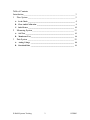
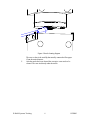
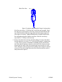
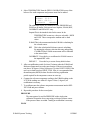
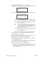
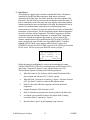
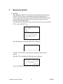
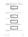
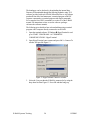
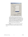
EBAM
Training Manual
Met One Instruments, Inc
1600 NW Washington Blvd.
Grants Pass, Oregon 97526
Telephone 541-471-7111
Facsimile 541-541-7116
Regional Service
3206 Main St. Suite 106
Rowlett, Texas 75088
Telephone 972-412-4715
Facsimile 972-412-4716
Table of Contents
Introduction_______________________________________________ 3
1
Flow System ___________________________________________ 5
A.
Leak Check _____________________________________________________ 5
B.
Flow Audit/Calibration ___________________________________________ 9
C.
Inlet Heater ____________________________________________________ 12
2
Measuring System ______________________________________ 13
A.
Self Test _______________________________________________________ 13
B.
Membrane Test _________________________________________________ 14
3
Data System __________________________________________ 18
A.
Analog Voltage _________________________________________________ 18
B.
Download Data _________________________________________________ 19
E-BAM Systems Training
2
11FEB03
Introduction
The E-BAM is an automated filter based TSP, PM10 and PM2.5 monitor. It has
the same basic operation as manual filter based samplers such as the SSI (Size
Selective Inlet High Volume Sampler) or the FRM (Federal Reference Method).
These manual samplers consist of three sub-systems, which are the following: a
Flow system, a Measuring system and a Data system.
Typically the flow system consists of an Inlet separator, filter holder, flow meter,
flow controller and a pump (Figure 1).
Figure 1 Typical flow system for a Manual Filter based Sampler
The measuring system requires a pre-weighed filter equilibrated at around 20
degrees Celsius and 45% RH. This filter is installed in the sampler and a known
volume of ambient air is drawn through the filter. The filter is then sent back to
the lab to be equilibrated and weighed again (Figure 2). The concentration
(µg/m3 ) is calculated by the change in mass of the filter divided by the volume of
air drawn though the filter.
Figure 2 Pre-weighing, Sampling and post-weighing in manual samplers.
E-BAM Systems Training
3
11FEB03
Finally, the data system tracks items such as the flow rate, filter and ambient
temperature, barometric pressure, Wind speed and direction etc. These parameters
are recorded with criteria to alert the user of invalid data.
Figure 3 Data collection system
The E-BAM also has a flow system, measuring system and a data system. The
advantage of the E-BAM is in the automation of the measuring system and the
simplification of both the data and flow systems. Each system can be
independently audited to assure accurate data. The following sections give details
on verifying the three systems of the EBAM.
E-BAM Systems Training
4
11FEB03
1
Flow System
A. Leak Check
During normal operation the flow system is under a vacuum of 160 mmHg (6
inHg). The leak check procedure increases this vacuum to 400 mmHg (16 inHg).
This 2.5 times increase in vacuum finds problems before they can affect the data.
To perform a valid leak test follow the step-by-step procedure below.
1. E-BAM is in the PUMP TEST screen located in the MAIN MENU/FIELD
CALIBRATION/PUMP TEST. This screen has two modes – LEAK CHECK
and PUMP TEST. Select LEACK CHECK.
2. Remove the PM10 inlet and replace with a Leak test valve (BX-305).
3. Close the valve on the leak test valve.
4. Flow rate should drop to under 1.5 LPM. If the flow is under 1.5 LPM remove
the Leak test valve and replace the PM10 head. If the flow is greater than 1.5
LPM proceed to Fixing a leak.
Fixing a leak
If you have performed the steps of a leak check and found that the E-BAM fails to
have a flow rate less than 1.5 LPM there is a problem with the integrity of the
flow system. Below is a list of solutions starting with the most common problems.
1. Nozzle/Vane build up – over time filter material can build up on the nozzle or
on the vane under the filter paper. It is recommended that these areas be
cleaned every 2 months or more frequently as needed. See the following steps
A – D for the step-by-step procedure to clean the nozzle/van area.
Nozzle Cleaning Procedure
During normal operation the nozzle of the E-BAM can have a build up of
filter material from on the sealing surface. Build up can also occur on the
Vane. The vane is the crosshatch piece under the filter paper. Both of these
must be cleaned periodically. Met One Suggest cleaning these areas every 2
months until the time interval is known.
A.
The nozzle needs to be lifted from the filter paper and the paper
removed from the nozzle area. In the main menu enter the LOAD
TAPE screen. The nozzle will automatically open. Lift the filter paper
out of the nozzle area.
B.
Using a cotton applicator with a small amount of isopropyl alcohol
gently clean the lip of the nozzle see Figure 4.
E-BAM Systems Training
5
11FEB03
Figure 4 Nozzle cleaning diagram
C.
The area to clean is the small lip that actually contacts the filter paper.
Clean the entire diameter.
After the nozzle has been cleaned the crosspiece vane needs to be
cleaned. The vane sits directly under the nozzle.
E-BAM Systems Training
6
11FEB03
Figure 5 Vane Cleaning Procedure
D.
Gently rub the cotton applicator across the four crosspiece sections of
the vane and around the circumference of the vane.
Replace the filter paper and the E-BAM is ready for operation.
After a complete cleaning retest according to the Leak Check procedure. If the
leak is above 1.5 LPM go to the next step.
2.
Remove the Sharp Cut Cyclone (SCC) and retest. If the E-BAM passes the
leak was in the SCC. Clean the SCC and replace orings as needed. If the EBAM fails go to the next step.
3.
Remove pump assembly – to remove the pump assembly see section 3.3.1.4
of the E-BAM manual. Do not remove the power from the PCB to the pump
and don’t remove the Tygon tubing from the pump ports. The pump will turn
on if the E-BAM is in the FIELD CALIBRATION / PUMP TEST screen.
Plug the top of the Nozzle assembly see Figure 6.
E-BAM Systems Training
7
11FEB03
Block Flow Here
Figure 6 Location to plug during the Fixing a Leak procedure
If the flow stays below 1.5 LPM the leak is in the Inlet tube assembly. Check
the orings for wear and replace as necessary. Remove the Inlet tube from the
top of the E-BAM and check the orings inside the black plastic coupler for
wear replace as necessary. Tighten all fittings and re-assemble. Recheck the
flow and tighten and replace until the unit passes. If the flow rate always
stayed above 1.5 LPM go to the next step.
4. Remove the chassis from enclosure and check fittings. To remove the chassis
from the enclosure see section 3.3.2.2 of the E-BAM manual. Complete steps
1-4 only. This is a process of elimination. Each fitting must be checked for a
leak. Start with the upstream connectors on the back of the chassis and work
down to the flow meter. After each connector has been removed do a Leak
check. When the Leak Check passes the last fitting removed must be replaced
or serviced. If no leak is found down to the flow meter then the flow meter is
faulty and must be replaced.
E-BAM Systems Training
8
11FEB03
B. Flow Audit/Calibration
After a successful leak check the next procedure to validate a flow system is a
Flow Audit. In an E-BAM the flow audit process has been simplified to allow
quick and accurate flow Audits. A Flow Audit is simply connecting a flow
standard to the E-BAM inlet and comparing readings. If the flow standard uses
tubing a BX-305 will allow easy connection to the E-BAM inlet. Be sure that the
flow standard and the E-BAM are measuring the flow on the same units and type.
The E-BAM has two flow types that are Actual flow and Standard flow see the EBAM manual for an explanation of these flow types. To check the setting of the
flow type in the E-BAM go the SETUP screens in the MAIN MENU. If the flow
audit shows that the E-BAM flow rate has an error greater than 2% a Flow
Calibration will need to be done.
To perform a valid Flow Calibration follow the step-by-step procedure below.
TEMPERATURE
1. Go to the MENU SCREEN and use the up and down arrow keys to select
FIELD CALIBRATION then press the SELECT key.
OPERATE
LOAD TAPE
SETUP
MEMORY
SELF TEST
FIELD CALIBRATION
SHUTDOWN/SHIPPING
VIEW ALARM LOG
ABOUT
2. The FIELD CALIBRATION screen has seven selections:
TEMPERATURE
PRESSURE
FLOW
MEMBRANE TEST
FILTER RH
FILTER TEMPERATURE
PUMP TEST
3. The first three selections TEMPERATURE, PRESSURE, and FLOW are
used in a flow audit. Actual Flow is calculated from all three components.
For a detailed description of how each is used to calculate flow see
Appendix C How to convert from Standard flow to Actual flow
.
E-BAM Systems Training
9
11FEB03
4. Select TEMPERATURE from the FIELD CALIBRATION screen. Note:
before a flow audit temperature and pressure must first be audited.
POINT: LOW
E-BAM: 21.8 C
REF: -30.0 C
CALIBRATE
DEFAULT
The calibration screens for TEMPERATURE, PRESSURE and
FLOW are all similar. Each screen has a Setpoint, E-BAM, REF,
CALIBRATE and DEFAULT entry.
Setpoint This is the intended value for the sensor. In the
TEMPERATURE screen two values are selectable – HIGH
and LOW. These correspond to ambient and ice bath
values.
E-BAM This is the measurement that the E-BAM is calculating for
the selected sensor.
REF
This is the value that the Reference sensor is calculating.
By entering the reference value into this entry and pressing
CALIBRATE the E-BAM measurement will be calibrated
to the entered value.
CALIBRATE Press this key to recalibrate the E-BAM sensor to
the inputted REF value.
DEFAULT
Press this key to restore factory default values.
5. Allow an equilibration period of at least 15 minutes when the E-BAM and
Reference temperatures are at the same location. If the test is an ambient
test (above 20 degrees Celsius [68 degrees F]) select POINT: HIGH. If the
test is an ice bath test select POINT: LOW. Note: it is recommended that
the ambient point (HIGH) be done first due to the long equilibration
period required for the temperature sensors to warm up.
6. Compare the reference temperature reading to the E-BAM reading on the
LCD. If the readings are within 0.5 degree Celsius (1 degree F) no
recalibration is necessary.
7. To recalibrate enter the reference temperature measurement into the REF:
XX.X field and press calibrate.
8. Repeat this procedure for the second point.
PRESSURE
The same protocol is used for PRESSURE with a single point
calibration. Repeat the above steps using a reference pressure sensor.
If the pressure values are within 2 mmHg no recalibration is necessary.
FLOW
E-BAM Systems Training
10
11FEB03
2. In the FIELD CALIBRATION screen select FLOW. Note:
TEMPERATURE and PRESSURE must be audited prior to the FLOW.
TEMPERATURE
PRESSURE
>FLOW
MEMBRANE TEST
3. The FLOW calibration screen is similar to all E-BAM calibration screens.
FLOW SP: 16.7 LPM
E-BAM: 16.7 LPM
REF: 16.4 LPM
CALIBRATE
DEFAULT
FLOW SP
This is the flow rate value. In the FLOW screen
three points are selectable – 14.0, 16.7, and 17.5 LPM.
E-BAM This is the measurement that the E-BAM is calculating
for the selected sensor.
REF
This is the value that the Reference sensor is calculating.
By entering the reference value into this entry and
pressing CALIBRATE the E-BAM measurement will be
calibrated to the entered value.
CALIBRATE Press this key to recalibrate the E-BAM sensor to
the inputted REF value.
DEFAULT
Press this key to restore factory default values.
4. Once a setpoint is selected the E-BAM will automatically turn on the
pump and regulate to the flow setpoint.
5. Remove the PM10 inlet and place the Reference flow audit device on the
inlet tube. Wait for 5 minutes for the flow to equilibrate.
6. Compare the reference flow to the E-BAM flow. If the flows are within
2% no recalibration is necessary.
7. To recalibrate the flow enter the Reference Flow Meter reading into the
REF: XX.X LPM entry and press CALIBRATE.
8. Repeat the above procedure for the remaining FLOW SP.
The FLOW system is checked and verified by these two tests – Leak
and Flow Tests. When the E-BAM passes both tests the flow system
will be working correctly.
E-BAM Systems Training
11
11FEB03
C. Inlet Heater
All E-BAMs are equipped with a moisture controlled inlet heater. The heater is
controlled by filter RH and filter temperature. Both sensors are located
downstream of the filter paper. The relative humidity is the main controller of the
inlet heater. The inlet heater is used to prevent condensation on the filter paper. If
there is condensation on the filter paper and water begins to collect along with the
airborne particulate the mass measurements will be high. By adding heat to the air
stream in a controlled manner condensation is avoided and proper mass
measurements are calculated. To ensure the sample does not get over heated filter
temperature is also measured. The filter temperature and the ambient temperature
are used to calculate a Delta-Temperature. The Delta-Temperature is the Filter
Temperature minus the Ambient Temperature. A maximum Delta-Temperature
can be set to limit the heat applied to the sample air. The set points for the
moisture-controlled heater can be modified in the SETUP menu. The SETUP
menu is located in the main E-BAM menu. Press MENU/SELECT and then
highlight SETUP with the curser and press MENU/SELECT again. Press
CONTINUE to bypass the DATE/TIME screen, the LOCATION screen and the
FLOW screen. The next screen is the HEATER screen see Figure 7.
RH SETPOINT: 45 %
DELTA-T SETPT: 8 C
RH CONTROL: ON
SAVE
CONTINUE
Figure 7 HEATER control screen.
Modify the settings by highlighting the value(s) and incrementing the reading
with the UP/DOWN keys. Met One recommends using an RH Setpoint of 45%
and a Delta-T setpoint of 8 degrees Celsius with RH control set to ON.
The Inlet Heater Operates according to the following parameters:
•
When RH control is ON, the heater will be turned ON when the RH is
above setpoint and will turn OFF 1 % below setpoint.
•
When the Delta-T setpoint is exceeded by 1 degree C the heater is turned
OFF. The Delta-T control over rides the RH setpoint control.
•
Delta-T is the result of the filter temperature minus the ambient air
temperature.
•
Anytime the pump is OFF, the heater is OFF.
•
Delta-T violations are reported to the Alarm log and sets the alarm relay.
•
A violation occurs when RH control is ON and the Delta-T reading
exceeds the Delta-T setpoint by 1 degree C.
•
Reset the alarm at power up and beginning of tape advance.
E-BAM Systems Training
12
11FEB03
2
Measuring System
A. Self Test
The E-BAM has a SELF TEST mode that will automatically test all parameters.
The SELF TEST will take several minutes and cannot be bypassed by the
operator. If any fault is located, the name and type of fault will be shown. If there
is a reasonable expectation that the operator could correct the fault, then an
instruction for correction is shown.
Go to the MENU SCREEN and use the up and down arrow keys to select SELF
TEST. Press the SELECT key.
OPERATE
LOAD TAPE
SETUP
MEMORY
SELF TEST
FIELD CALIBRATION
SHUTDOWN/SHIPPING
VIEW ALARM LOG
ABOUT
The E-BAM display will indicate SELF TEST RUNNING.
SELF TEST RUNNING...
*****************999
The SELF TEST will take several minutes and cannot be bypassed by the
operator.
After SELF TEST is finished, the following screen is displayed.
SELF TEST COMPLETE:
E-BAM FUNCTIONING
PROPERLY.
CONTINUE
Answer CONTINUE and the E-BAM will begin sampling.
E-BAM Systems Training
13
11FEB03
The Self Test can fail during any of the following sub-test:
Tape Broken
Nozzle Motor Failed
Beta Counts Failed
Flow System Failed
Pressure Sensor Failed
Figure 8 E-BAM Self Test failure screens.
If any fault is located during self-test, the name and type of fault will be shown. If
there is a reasonable expectation that the operator could correct the fault, then an
instruction for correction will be shown on the E-BAM display with step-by-step
instructions to test and verify the system integrity. The operator must
acknowledge any errors within one minute or the unit will automatically begin
operation
B. Membrane Test
Verification is accomplished using two calibration plates that represent a ZERO
and SPAN factory set calibration points. The set of calibration plates are unique to
each E-BAM. Always check that the serial number on the calibration plates match
the serial number of the E-BAM to be calibrated. The SPAN calibration plate has
a fragile membrane covering the hole. Never bump or touch the membrane.
Always keep the membranes in their protective plastic case when not in use.
When inserting the membranes into the E-BAM, be careful that you do not scrape
or rub the filter tape with the metal plate or a calibration error may result. The
membrane calibration will take about 16 minutes.
Figure 9 Inserting the Span/Zero plates
E-BAM Systems Training
14
11FEB03
Undo the latch and swing open the E-BAM door. To turn on the display, press
any key.
Go to the MENU SCREEN and use the up and down arrow keys to select FIELD
CALIBRATION then press the SELECT key.
OPERATE
LOAD TAPE
SETUP
SELF TEST
>FIELD CALIBRATION
SHUTDOWN/SHIPPING
VIEW ERROR LOG
ABOUT
From the CALIBRATE MENU select MEMBRANE TEST and press the
SELECT key.
TEMPERATURE
PRESSURE
FLOW
>MEMBRANE TEST
When you are ready to start the calibration press the START key.
MEMBRANE TEST
START ZERO TEST
START
The filter tape will advance, the nozzle will lower and the E-BAM will take a
four-minute blank ZERO count. Press CANCEL to re-start the test.
BLANK ZERO COUNT
CANCEL
After the four-minute count the nozzle will move up and wait for you to insert the
ZERO membrane.
E-BAM Systems Training
15
11FEB03
INSERT ZERO MEMBRANE
CANCEL
Insert the ZERO Membrane and the nozzle will lower and the E-BAM will take a
four-minute ZERO count see Figure 9.
CAL ZERO COUNT
CANCEL
After the four-minute sample the nozzle will move up and ask you to remove the
ZERO membrane.
REMOVE MEMBRANE
CANCEL
When the ZERO membrane is removed the nozzle will lower and the E-BAM will
take a four-minute blank SPAN count.
BLANK SPAN COUNT
CANCEL
After the four-minute blank SPAN count, the nozzle will move up wait for you to
insert the SPAN membrane.
INSERT SPAN MEMBRANE
CANCEL
After you insert the SPAN membrane the nozzle will lower and the E-BAM will
take a four-minute SPAN count see Figure 9.
E-BAM Systems Training
16
11FEB03
CAL SPAN COUNT
CANCEL
Note the test results and take out the SPAN membrane.
MEMBRANE TEST RESULT
ZERO MEMBRANE: PASS
SPAN MEMBRANE: PASS
OK
If the ZERO or SPAN test failed, re-run the test. If the failure continues, clean the
detector and re-run the test. If the failure persists, contact the factory service
center. Press OK to return to the CALIBRATION MENU.
The measuring system’s performance will be verified by completion of the Zero
and Span tests.
E-BAM Systems Training
17
11FEB03
3
Data System
A. Analog Voltage
The second data system is the analog output of concentration. This data system
requires a separate datalogger. The concentration will be calculated and converted
to a corresponding voltage by user selectable parameters. Analog voltage can be
either the hourly reading or the real-time reading. Full-scale voltage can be 1 volt,
2.5 volts, or 5 volts. To modify the analog voltage settings go to the SETUP
screens. The SETUP screens are found in the MAIN menu.
To verify that the outputted voltage is correct use the ANALOG VOLTAGE
screen. The ANALOG VOLTAGE screen is located in the MAIN MENU under
the FIELD CALIBRATION heading. There are three modes for this screen –
AUDIT, LOW, and HIGH.
The AUDIT mode allows the analog output to be set to any value from 0.000
volts up to the full-scale setting (full-scale is selected in the SETUP screens).
After selecting AUDIT move the cursor using the arrow keys to highlight the SET
PT value. Use the UP/DOWN keys to change the analog output setpoint. Using a
voltmeter measure the output voltage on the communication cable between the
White (positive) and Black (ground) wires. If the voltmeter reading matches the
SET PT value within 0.002 volts press exit to close this window. If the values
don’t match change the MODE to LOW.
MODE: AUDIT
SETPT: 2.000 V
EXIT
Figure 10 Analog Voltage screen in AUDIT mode.
The LOW mode allows the E-BAM analog output to be adjusted to match an
external datalogger or voltmeter. This adjustment is made at a low reading (.010
Volts). Connect the voltmeter, or datalogger, to the Communication Cable
between the White (positive) and Black (ground) wires. The voltmeter reading
should be that same as the OUTPUT reading on the E-BAM. If the readings are
different use the ADJUST command. Move the cursor using the RIGHT arrow
key until it highlights the ADJUST value. If the voltmeter is reading higher than
the OUTPUT reading of the E-BAM press the up arrow key to increase the
ADJUST value. If the voltmeter is reading lower than the OUTPUT reading of the
E-BAM press the DOWN arrow key to decrease the ADJUST value. Continue to
change the ADJUST value until the voltmeter reading matches within 0.001 volts.
Press SAVE and change the MODE to HIGH.
E-BAM Systems Training
18
11FEB03
MODE: LOW
OUTPUT: 0.010 V
ADJUST:-0.002
SAVE
DEFAULT
Figure 11 Analog Voltage screen in LOW mode.
The HIGH mode allows the E-BAM analog output to be adjusted to match an
external datalogger or voltmeter. This adjustment is made at a HIGH reading
close to the full-scale setting (full-scale is selected in the SETUP screens).
Connect the voltmeter, or datalogger, to the Communication Cable between the
White (positive) and Black (ground) wires. The voltmeter reading should be that
same as the OUTPUT reading on the E-BAM. If the readings are different use the
ADJUST command. Move the cursor using the RIGHT arrow key until it
highlights the ADJUST value. If the voltmeter is reading higher than the
OUTPUT reading of the E-BAM press the up arrow key to increase the ADJUST
value. If the voltmeter is reading lower than the OUTPUT reading of the E-BAM
press the DOWN arrow key to decrease the ADJUST value. Continue to change
the ADJUST value until the voltmeter reading matches within 0.001 volts. Press
SAVE and change the MODE to TEST.
MODE: HIGH
OUTPUT: 4.990 V
ADJUST:-0.001
SAVE
DEFAULT
Figure 12 Analog Voltage screen in HIGH mode.
Use the voltmeter to verify that the correct voltage is outputted through the
communication cable (Part number 9321). in the TEST mode at a low and high
voltage reading.
B. Download Data
The E-BAM has a 10 Channel datalogger. These channels record the
following information:
1 – Real time Concentration
2 – Hourly Concentration
3 – Flow
4 – Wind Speed
5 – Wind Direction
6 – Ambient Temperature
7 – Filter Temperature
8 – Filter Relative Humidity
9 – Ambient Relative Humidity
10 – Battery Voltage
E-BAM Systems Training
19
11FEB03
The datalogger can be checkout by downloading the internal data.
Data may be downloaded through the following methods: using TUS
software provided with each E-BAM, MicroMet Plus or AQ software
purchased from Met One Instruments, a terminal program with ESC
sequence commands or a terminal program with simple commands.
For a complete list of ESC commands see section 10 of the E-BAM
manual. For instructions on how to use the software packages
reference the software manuals.
The following gives details on how to download data using a terminal
program with a computer directly connected to an E-BAM.
1. Open the terminal software. If Windowst HyperTerminal is used
go to START / PROGRAMS / ACCESSORIES /
COMMUNICATIONS / HyperTerminal.
2. Open HyperTerminal, enter a name and press OK. A Connect To
window will open like Figure 13.
Figure 13 HyperTerminal Connect to window.
3. Select the Com port that the E-BAM is connected to by using the
drop down list from Figure 13. Press OK and that brings up
E-BAM Systems Training
20
11FEB03
Figure 14 HyperTerminal communications protocol window.
In communications protocol window set the Bits per second
window to match the setting on the E-BAM. The bits per second
setting (baud rate) is found in SETUP screens. The SETUP screens
are found in the MAIN MENU. The serial port baud rate can be set
to 300, 600, 1200, 2400, 4800, 9600, 19200 and 38400. Use the
arrow keys to make any changes. Note: the default setting is 9600.
The other settings are 8 data bits, NONE parity, 1 stop bit, and
NONE for flow control. Press OK and the setup is complete.
4. In the HyperTerminal window press ENTER 3 times.
5. Then press the number 2. This will download all the data from the
E-BAM.
Once the data are downloaded check for missing time periods or aberrant data.
This will verify that the averaging, recording and downloading of the data system
is correct.
E-BAM Systems Training
21
11FEB03