Transcript
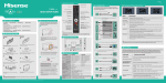
ES-M135202-1
QUICK SETUP GUIDE
HDMI / COMPONENT IN / AV IN
Screw: (M4 ×12) ×4
• If the item is not specified in the accessories list, it should be provided by customer.
2
Switch to DTV Radio program
Analog/ Digital TV
Start video recorder
Zoom image
Mute the sound
Select USB-Digital
Media player mode
INSTALLING THE STAND
<CH>
Select the channel
<VOL>
Adjust the volume.
STANDBY
Turn on the TV or put the TV in standby mode.
Fast access to your saved
favorite programs
Red, Green, Yellow and Blue
are used in media mode
Exit: Exit all menu display
6
Enter or confirm the operation,
Up/Down/Left/Right
HDMI Cable
(not included)
Red(R)
White(L)
MAKING CONNECTIONS
Yellow(Video)
TV Side View
White(L)
PB
Channel Up/ Channel Down
L
Yellow(Video)
Volume Up/ Volume Down
Audio Cable
(not included)
PR/CR
Red(R)
Video
Camera
Satellite
antenna
L
PR/CR
PR
PB/CB Component Cable PB/CB
(not included)
Y
Y
Satellite Receiver
PB
Y
Equipment with A/V jacks
Component
USB
1,2,...numbers: For direct channel access
Connect a USB 2.0 device port for browsing photos, listening music and watching
recorded movies.
• Press [◄ / ►] button to select USB in the Source menu, then press [OK] button
to enter.
Base
Freeze picture
To return to the last view program
Time shift in DTV Mode
Text, Size, Reveal, Hold, Index, Subpage
(refer to teletext function)
Video recorder list
TV Bottom Panel
Play/ Pause, Stop, etc.
are used in media mode
3
TV Set
Set-top box
R
White(L)
Sound mode selecting
2
DVD Player/Recorder
Video
Y
Neck
R
White(L)
AV Cable
(not included)
Red(R)
Picture mode selecting
1
Red(R)
A/V OUT
Electronic program guide
Display informations
EXTERNAL DEVICES
VCR
FOR ILLUSTRATION ONLY.
Powering up or down the TV requires several seconds of processing time.
Do not rapidly turn the TV on/off as abnormal operation may occur.
Display the subtitle
content of the signal
Display the main menu
/ Back menu display
TV JACK
NOTES
Select Audio language
CAUTION
1. Use the screws (ST4 x 10F) x 4 to fix the Neck and Base.
2. Attach the stand to the TV set as shown in the picture.
3. Use the screws (M4 x 12) x 4 to fix the Stand tightly.
Select among the different signal sources.
Set the sleep time
Mono/Stereo operation,
Audio select button
Carefully place your TV facedown on a soft, cushioned surface to prevent
damage to the TV or scratching to the screen.
SOURCE
HDMI
Screw: (ST4 ×10F) ×4
Open the OSD menu
R
Batteries: AAA × 2
Available source selection
MENU
L
AV IN
Remote Control
Quick Setup Guide
Remote sensing Window
Power button
Red light up in standby mode. Blue light up in power on mode
VIDEO
User Manual
REMOTE FUNCTIONS
Remote Indicator
R
4
ACCESSORIES LIST
Receive remote signals from the remote control.
Do not put anything near the sensor, as its function may
be affected.
L
PR
COMPONET IN
1
Remote Sensor
HDMI
32D33
Connect an HDMI cable or Component in/AV IN Adapter from an external A/V
equipment. No sound connection is needed for HDMI to HDMI connection. If the
device signal resolution does not match the specification table you need to change the
setting of device according to the table. Please consult your device user manual for
instruction.
• To select the HDMI / Component / AV
Press [Source] button, when the list of Input Source appears, press [▲/▼] to select
the source [HDMI] / [Component] / [AV], then press [OK] to connect.
Portable Storage
Device
ER-22601A
COAXIAL audio
CHANGE THE BATTERIES
1. Slide open the battery cover on the back of the remote control.
2. Install two AAA size (1.5V) batteries. Match the “+” and “-” signs on the batteries to the
signs on the battery compartment.
3. Close the battery cover.
1
Stand
2
Gently Push
3
ANT/CABLE IN
Connect an antenna or cable TV to this jack.
HDMI
HDMI (High-Definition Multimedia Interface)provides
uncompressed video data and digital audio data.
Support: 480i\480p\576i\576p\720p\1080i\1080p
COMPONENT IN
Connect to a DVD player, Digital Set-Top-Box, or other A/V
devices with component (YPBPR) video and audio output jacks.
Component audio Jack share AV IN audio Jack.
Support: 480i\480p\576i\576p\720p\1080i\1080p
Connect to the composite video and audio (L/R) output jacks
on external video devices.
NOTE
Product image is only for reference, actual product may vary in appearance.
3
AV IN
NOTES
INSTALLING A WALL-MOUNT BRACKET
Wall-mount Bracket
AUDIO OUT
To prevent internal damage to the TV and ensure the TV is mounted securely, be sure
to use fixing screws (Not provided) which are 7 mm to 9 mm in length when measured
from the attaching surface of the mounting hook.
Screws M4
7~9 mm
Wall-mount Bracket
COAXIAL
Connect to an external digital audio device.
TV JACK
Outdoor
Antenna
6m
15°
15°
8m
6m
6m 30° 30°6m
8m
TV FRONT
Turning the TV On for the First Time
Connect an RF cable from the TV’s input called “ANT/CABLE IN” and to your TV
Aerial socket.
OSD Language:
Press [◄ / ►] button to select the language to be used for menus and message.
Mode Setting: Press [◄ / ►] button to select mode.
Country: Press [◄ / ►] button to select the country you want to.
Auto Scan: Press [◄ / ►] button to select Mode: DTV+ATV, DTV, ATV.
VGA & AUDIO
Connect a VGA cable and an audio cable from the PC.
• To select the PC: Press [Source] button, when the list of In Source appears,
press [▲/▼] to select the source PC, then press [OK] to connect.
the TV’s rear cover
Wall-mount screw size (mm)
200 × 100
M4
Follow instructions provided with the wall bracket.
Powerless
Bass Speaker
Speaker
AUDIO OUT Connect Headphone for audio out of the TV.
7
SPECIFICATIONS
Size with base (mm)
Size without base (mm)
Gross Weight (kg)
Net Weight (kg)
(with base/without base)
Screen Diagonal Size
Screen Resolution
Sound Output (RMS)
Power Consumption
Power Supply
Colour System
Television System
Environmental
Conditions
Component mode
VGA mode
HDMI mode
736×180×500
736×67.8×455
7.9
6.2/5.0
32 inches
1366 × 768
6W+6W
50 W
100V - 240V
50Hz/60Hz
PAL
PAL I B/G D/K, DVB-T
Temperature: 5°C - 45°C
Humidity: 20% - 80% RH
Atmospheric pressure: 86 kPa - 106 kPa
480i\480p\576i\576p\1080i\1080p
640×480, 800×600, 1024×768, 1280×1024 60Hz
480i\480p\576i\576p\1080i\1080p
Attention: Excessive sound pressure from earphones and headphones can
cause hearing loss.
PC/DVI AUDIO IN
NOTE
Features, appearance and specifications are subject to change without notice.
CH
V
V
MENU SOURCE
VOL
V
AC Power ON/OFF
STANDBY
V
If you are not sure of your ability to complete the installation, contact a
professional installer or service technician for assistance. The manufacturer is
not responsible for any damages or injuries that occur due to mishandling or
incorrect assembly.
Be sure to use the provider spacers between the TV and the bracket when
attaching the mount.
VGA
Audio Amplifier
Headphone
ANT/CABLE IN
Screw
Wall-mount hole pattern (mm)
Coaxial Cable
(not included)
AUDIO OUT
ANT Connect an outdoor VHF/UHF antenna.
1. The maximum distance is 8
meters in front of the TV set.
2. The remote control is effective
within 30 Degrees of horizontal
angle, or 15 Degrees of vertical
angle at maximum distances of
6 meters.
5
Video , MP3, JPEG play and software update.
Check the jacks' for position and type before making any
connections.Loose connections can result in image or color
problems. Make sure that all connections are tight and secure.
REMOTE CONTROL RANGE
Wall monuted-screws
M4 x 20mm
COAXIAL
Connect to headphone for private listening.
USB
EXTERNAL DEVICES
TV JACK
VGA/PC/DVI AUDIO IN Connect to a PC or other devices with a VGA interface.
Dispose of your batteries in a designated disposal area. Do not throw the
batteries into fire.
Do not mix battery types or combine used batteries with new ones.
Remove depleted batteries immediately to prevent battery acid from leaking
into the battery compartment.
If you do not intend to use the remote control for a long time, remove the
batteries.
The effective range of remote control is suggested in the figure below.
If you want to attach the TV to a wall-mount bracket (not provided),Make sure the TV
is laid face-down on a clean,safe, and cushioned surface.
Attach purchased bracket on the TV with the 4 screws (not provided) .
1. Use a coaxial cable to connect the A/V device’s digital audio in jack to the TV’s
DIGITAL AUDIO OUT jack.
2. Plug the connected devices into the mains socket before switching on the TV.
3. Select the corresponding source from the TV.
Remote Sensor Remote Indicator
PC
you refer to the Trouble Shooting tips in the User Manual.