1
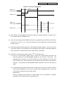
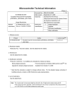
Microcomputer Technical Information
CP(K), O
Document No. ZBG-CD-04-0068
QB-78K0MINI
78K0 Series On-Chip Debugging Emulator
Date issued
September 24, 2004
Issued by
Development Tool Group
Multipurpose Microcomputer Systems Division
3rd Systems Operations Unit
NEC Electronics Corporation
Usage Restrictions
Related
documents
QB-78K0MINI User’s Manual:
U17029EJ2V0
1/1
Notification
classification
√
Usage restriction
Upgrade
Document modification
Other notification
1. Affected product
Control codeNote: A, B, C
QB-78K0MINI
2. New restriction
Restriction No. 1 has been added. See the attachment for details.
3. Workaround
See the attachment for details.
4. Modification schedule
Products in which restriction No. 1 is modified are scheduled for release as follows.
Newly shipped products:
From the shipment of July 2004 (control code: C)
Upgrade for already shipped products: Available from October 2004
* Note that this schedule is subject to change without notice. For the detailed release schedule of
the modified products, contact an NEC Electronics sales representative.
5. List of restrictions
See the attachment for details.
6. Document revision history
QB-78K0MINI 78K0 Series On-Chip Debugging Emulator Usage Restrictions
Document Name
ZBG-CD-04-0068
Note
Issued on
September 24, 2004
Description
Addition of bug (No. 1)
The “control code” is the second digit from the left in the 10-digit serial number in the warranty supplied with
the product you purchased (if it has not been upgraded).
If the product has been upgraded, a label indicating
the new version is attached to the product and the x in V-UP x on this label indicates the control code.
Control codes B and C are functionally equivalent.
ZBG-CD-04-0068 Attachment 1/4
Notes on Using QB-78K0MINI
This document is revised from the document “QB-78K0MINI (Control Code: A, B) Operating Precautions”
(document number: SUD-DT-04-0157) included in the CD-ROM (ID78K0-QB Disk V2.81 2004.6.22), so
refer to this latest document.
1. Product Version
Note
Control CodeNote
Remark
A
−
B
−
C
−
The “control code” is the second digit from the left in the 10-digit serial number in the warranty supplied with
the product you purchased (if it has not been upgraded).
If the product has been upgraded, a label
indicating the new version is attached to the product and the x in V-UP x on this label indicates the control
code. Control codes B and C are functionally equivalent.
2. Product History
No.
1
Bugs and Changes/Additions to Specifications
The flash data in the target device is erased before the debugger is started
Control Code
A
B, C
×
√
×: Applicable, √: Not applicable or already corrected
3. Details of Bugs and Added Specifications
No. 1 The flash data in the target device is erased before the debugger is started
[Description]
The flash data in the target device is erased if the QB-78K0MINI is connected to a PC via a USB and
the power to the target is turned on when the value at address 0x84 is 0x03 and the ID code is other
than 0xFF.
[Workaround]
Set the value at address 0x84 to 0x02.
This bug has been corrected in control code B or later.
ZBG-CD-04-0068
Attachment 2/4
4. Caution
The underlined description has been added to Caution in 3.1.2
Clock socket for target device in the
user’s manual.
Caution Be sure to turn off the emulator's power supply before inserting or removing a
clock in the clock socket for the target device. In addition, do not mount a clock in
the clock socket when “System” is selected in the “Main Clock” field in the
Configuration dialog box of the debugger.
5. Difference Manual
This section explains modifications and additions to the user’s manual (U17029EJ2V0UM00).
♦Throughout
Incorrect: RESET
Correct:
RESET
Incorrect: RESET_OUT
Correct:
RESET_OUT
♦Pages 11 to 13, 30, 38, and 40
• The OCD Checker is bundled with the CD-ROM supplied with the QB-78K0MINI.
♦Pages 25 and 26
Incorrect: For description of pull-down resistance values, see the target device's User's Manual.
Correct:
Connect a pull-down resistor of 470 Ω or higher.
♦Pages 42 and 43
Replace the contents of CHAPTER 5 RESTRICTIONS with the following.
(1) A delay period of about 50 µs from cancellation of a target reset (RESET_IN) to cancellation of a
target device reset (RESET_OUT) (the period from when the target reset (RESET_IN) becomes
low to when the target device reset (RESET_OUT) becomes high) is required for mode setting.
See Figure 5-1 below.
(2) A delay period of about 25 µs is required from input of a target reset (RESET_IN) to when the
target device is reset (RESET_OUT).
See Figure 5-1 below.
ZBG-CD-04-0068
Attachment 3/4
Figure 5-1. Timing of Target Reset
50 µs
RESET_IN
When shorter than 50 µs
15 µs
RESET_OUT
RESET_IN
When longer than 50 µs
25 µs
RESET_OUT
(3) When setting on-chip debugging mode via the normal port, without using pins X1 and X2, two of
the user ports will be unavailable for use.
(4) When the user program is downloaded, flash memory programming is performed by self-writing.
At that time, be sure to use a clock that supports the self programming routine's operating
frequency range.
(5) A high-level signal is always output from to the FLMD0 pin during emulation. Be sure to connect
a pull-down resistor to the FLMD0 pin, and manipulate this pin based on high/high-impedance
levels, rather than on high/low levels, when using ports for manipulation.
(6) Restriction on using the self-check board (V1.0)Note for operation check
<1> There is a communication problem due to a bug in the microcontroller mounted on the
self-check board when the QB-78K0MINI operates on the subclock or Ring-OSC. The
debugger takes a measure to avoid this problem by forcibly switching to the main clock
when a break occurs, and re-switches to the subclock or Ring-OSC when the program is
executed. Consequently, the QB-78K0MINI always operates on the main clock during a
break.
<2> A fail-safe break (Uninitialize Stack Pointer; a break that occurs due to a failure to perform
stack pointer initialization) occurs when an internal reset is generated due to a bug in the
microcontroller mounted on the self-check board.
[Workaround]
Stop the watchdog timer operation or repeat starting the count operation to suppress
generation of the internal reset by the watchdog timer.
ZBG-CD-04-0068
Attachment 4/4
Note The part number is shown as "QB-78K0KX1H-TB X.X" on the label attached to the
device mounted on the self-check board. "X.X" indicates the version.
6. Cautions
General cautions on handling this product
1. Circumstances not covered by product guarantee
• If the product was disassembled, altered, or repaired by the customer
• If it was dropped, broken, or given another strong shock
• Use at overvoltage, use outside guaranteed temperature range, storing outside guaranteed
temperature range
• If power was turned on while the USB cable or target system connection was in an unsatisfactory
state
• If the USB cable, connection cable, or the like was bent or pulled excessively
• If an AC adapter other than the one supplied with the product is used
• If the product got wet
• If the product and target system were connected while a potential difference existed between the GND
of the product and the GND of the target system
• If a connector or cable was removed while the power was being supplied to the product
• If an excessive load was placed on a connector or socket
2. Safety precautions
• If used for a long time, the product may become hot (50°C to 60°C). Be careful of low temperature
burns and other dangers due to the product becoming hot.
• Be careful of electrical shock.
There is a danger of electrical shock if the product is used as
described above in 1 Circumstances not covered by product guarantee.