1
Microcontroller Technical Information
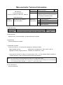
QB-78K0LX3
In-Circuit Emulator for
78K0/LC3, 78K0/LD3, 78K0/LE3, 78K0/LF3
Document No.
ZBG-CD-07-0049
Date issued
August 8, 2007
Issued by
Development Tool Solution Group
Multipurpose Microcomputer Systems Division
Microcomputer Operations Unit
NEC Electronics Corporation
Usage Restrictions
Related
documents
QB-78K0LX3 User’s Manual:
U18511EJ1V0UM00
Notification
classification
√
1/2
Usage restriction
Upgrade
Document modification
Other notification
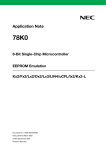
1. Affected product
Outline
Control CodeNote
In-circuit emulator for 78K0/LC3, 78K0/LD3, 78K0/LE3, 78K0/LF3
A, B
Product
QB-78K0LX3
2. New restriction
Restriction No. 4 has been added. See the attachment for details.
3. Workaround
See the attachment for details.
4. Modification schedule
Product in which No. 4 is corrected is scheduled for release as follows.
Newly shipped products:
Shipments as of September 6, 2007 (control code: C)
Upgrade for already shipped products: Available from September 3, 2007
* Note that this schedule is subject to change without notice. For the detailed release schedule of
modified products, contact an NEC Electronics sales representative.
Note The “control code” is the second digit from the left in the 10-digit serial number.
If the product has been upgraded, the control code can be checked in the About dialog box in the ID78K0-QB.
“X” in version information “IECUBE **** X F/W: V*.**” is the control code.
5. List of restrictions
See the attachment.
ZBG-CD-07-0049
6. Document revision history
Document Number
Issued on
Description
ZBG-CD-07-0022
April 2, 2007
Newly created
ZBG-CD-07-0049
August 8, 2007
Control code A, B
2/6
2/2
ZBG-CD-07-0049
1/6
Operating Precautions for QB-78K0LX3
This document describes restrictions applicable only to the emulator and restrictions that are planned for
correction in the emulator.
Refer to the following documents for the restrictions in the target device.
• User’s manual of target device
• Restrictions notification document for target device
Also refer to the user’s manual of the emulator for cautions on using the emulator.
1. Product Version
Control CodeNote
Emulation CPU
Remark
A
μPD78F0495 1.0
−
B
μPD78F0495 1.0
−
C
μPD78F0495 1.1
−
Note
The “control code” is the second digit from the left in the 10-digit serial number.
If the product has been upgraded, the control code can be checked by selecting [About] from the
[Help] menu when the ID78K0-QB is running.
“X” in version information “IECUBE **** X F/W: V*.**” is the control code.
ZBG-CD-07-0049
2/6
2. Product History
No.
Bugs and Changes/Additions to Specifications
1
Bug in interrupts
2
Self-programming function does not operate normally
Control Code
A
B
C
×
{
{
Deleted (not applicable to this product)
3
Support for emulation for boot swap function
×
{
{
4
Bug in TM51 source clock
×
×
{
−: Specification change not yet implemented, ×: Restriction applicable, {: Restriction corrected or specification
change implemented)
3. Details of Bugs and Added Specifications
No. 1
Bug in interrupts
[Description]
If an interrupt occurs immediately after accessing any of the following registers, execution does not jump to
the interrupt vector but jumps to an incorrect address.
Address
Register Name
FF0BH
P11
FF2BH
PM11
FFB0H
LCDMD
FFB1H
LCDM
FFB2H
LCDC0
FFB5H
PF2
FFB6H
PFALL
[Workaround]
There is no workaround.
[Correction]
This issue has been corrected in products with control code B and later.
No. 2
Self-programming function does not operate normally
[Description]
This issue was deleted because this restriction was not applicable.
No. 3
Support for emulation for boot swap function
[Description]
Emulation for the boot swap function is now supported. When using this function, use the tools in the
following combinations.
• ID78K0-QB:
V3.00 or later
• QB-78K0LX3: Control code B or later
ZBG-CD-07-0049
No. 4
3/6
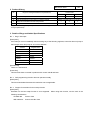
Bug in TM51 source clock
[Description]
If the TCL512 to TCL510 bits are set to “111” in timer clock selection register 51 (TCL51) for 8-bit timer/event
counter 51 (TM51), the timer operates at fPRS/212 and the output signal of timer H1 is not selected.
TCL512
TCL511
TCL510
Target Device
Emulator
1
1
1
Output signal of timer H1
fPRS/212
fPRS: Peripheral hardware clock
[Workaround]
There is no workaround.
[Correction]
This issue will be corrected in products with control code C and later.
4. Changes in User’s Manual
The following change has been added to the In-Circuit Emulator QB-78K0LX3 Operation User’s Manual.
(document number: U18511EJ1V0UM00)
4.1 Addition of note
• Location
CHAPTER 5 NOTES (p. 45)
• Description
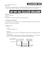
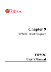
When LVI reset occurs, “RESET”, which is displayed in the status bar of the debugger during reset
periods, blinks.
The blinking makes it seems as if the reset is set and cancelled repeatedly. It is in the reset state,
however. It is just an indication problem in the debugger. See the following figure.
Power supply voltage
(VDD pin or EXLVI pin)
LVI reset occurs
Reset is cancelled
LVI detection voltage
Time
Reset
(“RESET” in status bar blinks during this period.)
ZBG-CD-07-0049
4/6
4.2 Correction on mounting and connecting connectors
• Location
2.5.2 Mounting YQ to TC (p. 23)
• Description
[Before change]
(1) After confirming that there are no broken or bent YQ contact pins, fit YQ in the TC and fasten
the screw. If repeatedly inserting and removing, be sure to inspect the YQ pins before fitting. If
pins are bent, correct them using something thin and flat such as the edge of a knife.
(2) Accessory holes are needed in prescribed positions in four places in the board for connecting
YQ. Fasten YQ to the TC on the target system using the supplied M2 x 10 mm screws. The
thickness of a board corresponding to these screws is 1.0 to 2.0 mm. Fasten the screws
equally in the four corners using a #0 or #1 Phillips precision screwdriver or torque driver. The
tightening torque of the screws is 0.054 Nm (MAX.).
Too great tightening causes bad
connections.
Four screws for fitting to the TC (M2 x 10 mm / 4 units) are included with YQ.
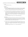
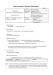
[After change]
(1) After confirming that there are no broken or bent YQ contact pins, fit YQ in the TC and fasten it
using the supplied YQGUIDE (for the fastening method, see the next step, (2)). If repeatedly
inserting and removing, be sure to inspect the YQ pins before fitting. If pins are bent, correct
them using something thin and flat such as the edge of a knife.
(2) Fasten YQ to the TC on the target system using the supplied YQGUIDE. Fasten the screws
equally in the four corners using the supplied flat-blade screwdriver or a torque driver. The
tightening torque of YQGUIDE is 0.054 Nm (MAX.).
Too great tightening causes bad
connections.
Four screws for fitting to the MA (M2 x 10 mm / 4 units) are included with YQ.
ZBG-CD-07-0049
EA
YQGUIDE supplied with YQ
YQ
TC
Target system
5/6
ZBG-CD-07-0049
6/6
5. Cautions
General cautions on handling this product
a. Circumstances not covered by product guarantee
• If the product was disassembled, altered, or repaired by the customer
• If it was dropped, broken, or given another strong shock
• Use at overvoltage, use outside guaranteed temperature range, storing outside guaranteed
temperature range
• If power was turned on while the AC adapter, interface cable, or target system connection was in an
unsatisfactory state
• If the AC adapter cable, interface cable, emulation probe, or the like was bent or pulled excessively
• If an AC adapter other than the one supplied with the product is used
• If the product got wet
• If the product and target system were connected while a potential difference existed between the
GND of the product and the GND of the target system
• If a connector or cable was removed while the power was being supplied to the product
• If an excessive load was placed on a connector or socket
• If a metal part of the power switch or another such part comes in contact with an electrostatic charge.
• If the product is used or stored in an environment where an electrostatic or electrical noise is likely to
occur
b. Safety precautions
• If used for a long time, the product may become hot (50°C to 60°C). Be careful of low temperature
burns and other dangers due to the product becoming hot.
• Be careful of electrical shock. There is a danger of electrical shock if the product is used as described
above in a. Circumstances not covered by product guarantee.
• The AC adapter supplied with the product is exclusively for this product, so do not use it with other
products.