1
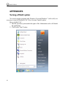
CVFC Energoform
program
Version 1.2.2
User’s manual
2011
MMARS-ENERGO
CONTENTS
CONTENTS ........................................................................................................ 2
SCOPE ............................................................................................................... 4
INSTALLATION AND START............................................................................ 7
System requirements .................................................................................... 7
Installation...................................................................................................... 8
Start............................................................................................................... 10
Removing the software ............................................................................... 10
DATA FORMATS ............................................................................................. 11
Format of commands for the reference instrument ................................. 11
Format of commands for the generator .................................................... 11
Format of commands for CVFC.................................................................. 12
USING THE SOFTWARE................................................................................. 13
Initialization .................................................................................................. 13
Main window ................................................................................................ 14
List of profiles ................................................................................................................. 15
Profile parameters.......................................................................................................... 17
Readings from devices under test.................................................................................. 19
Main menu .................................................................................................... 36
“File” menu ..................................................................................................................... 36
“Mode” menu.................................................................................................................. 39
“Settings” menu.............................................................................................................. 41
“?” menu......................................................................................................................... 46
“Profiles” contextual menu ........................................................................ 46
“CVFC parameters” contextual menu ....................................................... 47
Test procedure............................................................................................. 51
Nominal values ............................................................................................ 56
Viewing and exporting measurement results ........................................... 59
APPENDICES .................................................................................................. 66
2
CVFC Energoform program. User’s manual
Turning off UAC option................................................................................66
TECHNICAL SUPPORT ...................................................................................69
3
MMARS-ENERGO
SCOPE
The “CVFC Energoform” program (“EnfCalibrationRig” or the program below) is a
software component for MTS ME 3.1K test system intended for work with devices
measuring electrical power quantities and power quality parameters, namely “Energomonitor-3.1”, and “Energomonitor-3.1K”, (hereinafter referred to as “the reference instrument”) as well as with “Energoform-3.1” test signal source (hereinafter referred to as
“the generator”).
CVFC Energoform program makes it possible to:
1. Test single- and three-phase electric energy meters in the automatic mode with
use of CVFC Converter (Current/Voltage-to-Frequency Converter, CVFC below);
2. Perform sensitivity and creep tests for test single- and three-phase electric energy meters in the automatic mode with use of CVFC;
3. Adjust test single- and three-phase electric energy meters in the semi-automatic
mode with use of CVFC (up to 15 meters at a time);
4. Test single- and three-phase meters (instrument converters) used to convert
various electrical quantities into DC voltage or current in the automatic mode
with use of CVFC (up to 15 devices at a time);
5. Adjust single- and three-phase meters used to convert various electrical quantities into DC voltage or current in the semi-automatic mode with use of CVFC
(up to 15 devices at a time);
6. Read, via a serial port, and display test results on a PC screen in both the testing
and adjustment modes;
7. Create test procedures for electric energy meters and instrument converters
which may then be saved to / loaded from a file stored on the hard disc;
8. Activate signals included in previously created test procedures on the generator's
outputs both in the testing and adjustment modes;
9. Read test results from CVFC via Ethernet interface (10 Mbit/s) both in the
testing and adjustment modes;
10. Display results of testing and adjustment on the PC screen;
11. Save results of testing and adjustment to files on the hard disc for further loading
and viewing;
12. Export test results into MS Excel files and into MS Word and MS Excel templates.
4
CVFC Energoform program. User’s manual
Testing can only be performed with use of CVFC. Up to 15 devices of the same type
can be tested at a time. Devices under test must be connected to the test system according
to the appropriate connection scheme and in the same way.
Testing or adjustment of meters is performed by the method of comparing meter-under-test and reference frequencies. When testing meters, each meter's pulse output
is connected to the pulse input of one CVFC. The pulse output of the reference device is
connected to the reference pulse output of each CVFC. The program provides for testing
of meters measuring power of the following types:
• active;
• apparent;
• reactive (geometrical method);
• reactive (cross-connection method);
• reactive (phase-shift method).
The program makes it possible to carry out meter sensitivity and creep tests.
When testing instrument converters, DC voltage or current output of each device
must be respectively connected to the DC voltage or current measuring input of one
CVFC. For single-phase instrument converters, each phase of the test system can be used
independently and thus connected to three different devices.
The “CVFC Energoform” program provides for testing of converters measuring the
following:
• AC voltage;
• AC current;
• Active power;
• Apparent power;
• Reactive power (with geometrical, cross-connection and phase shift methods);
• Frequency.
The program supports testing of instrument converters measuring frequency and
voltage with nominal AC voltage of up to 1000V.
CVFC has the following measuring ranges that can be selected as DC outputs:
• [0 … +5] V;
• [0 … +10] V;
• [–5 … +5] V;
• [–10 … +10] V;
• [0 … +20] mA;
• [+4 … +20] mA;
• [0 … +5] mA;
• [–5 … +5] mA.
5
MMARS-ENERGO
CVFC
controls
and
connectors
are
described
in
the
“DC
CURRENT/VOLTAGE-TO-FREQUENCY CONVERTER CVFC” User's Manual.
Caution!
CVFC Energoform program works with “Energomonitor-3.1” and “Energomonitor-3.1K” instruments (design versions with 9 current ranges, firmware versions from
3.4.1 to 4.0 and 5.1.1 or above) in combination with CVFC Converter (firmware version
1.1 or above).
6
CVFC Energoform program. User’s manual
INSTALLATION AND START
System requirements
CVFC Energoform works under operation systems MS Windows 2000, XP, Vista
and Windows 7 (32- or 64-bit architecture) supporting the Cyrillic alphabet.
The following PC configuration is recommended for proper functioning of the
program:
• Processor: Pentium III at 700 MHz or more powerful;
• at least 256 Mb RAM;
• Consumed disc space: at least 3 MB for installation (20 MB of additional space, if
your operating system does not include the Microsoft .NET Framework package,
version 4.0);
• Video adapter of 1024x768 resolution;
• CD drive for software installation;
• mouse or compatible pointing device;
• Two free COM-ports (RS-232);
• Ethernet adapter with RJ-45 connector for connection of CVFC.
For a more convenient work with large volumes of data a more powerful computer
may be requisite.
CVFC can be connected to the PC Ethernet connector via a LAN switch or directly
via a network cable with inverse cabling.
To simultaneously operate multiple CVFCs, use switches to connect them to LAN.
Caution!
If you have the program version lower than 1.2.0 installed on your PC, before installing the current version, it is recommended to uninstall the program, and then install
the update.
Caution!
CVFC Energoform program can do without MS Excel and MS Word (MS Office
package) installed on your computer. Test results are saved to a file on the hard disc
without use of MS Excel and MS Word applications. However, to view and print exported test results, you shall have these applications on your PC.
7
MMARS-ENERGO
Caution!
To correctly run the program under Windows Vista and Windows 7, it is necessary
to turn off Windows UAC (User Account Control) option. The procedure of turning off
UAC is described in the corresponding Appendix.
Installation
1. Insert the installation CD into the CR-ROM drive.
2. Close all working Windows applications and launch the file setup.exe from the
installation CD.
3. At the beginning, the program starts by checking if there is a package “Microsoft .NET Framework version 4.0” installed on your computer. If it is not found,
you will be asked to install the package, otherwise installation will be aborted.
At the completion of installation, you may be asked to restart your computer.
4. Follow the on-screen instructions of the installation program. The program
performs in Wizard’s style. It guides you through a suite of Windows dialog
boxes with questions, instructions or menus in them. Each box is associated with
some actions or decisions for you to take. When done, the user typically presses
“Next” button to go further. Alternatively, he may click on “Back” to undo his
actions and repeat the step, or force “Cancel” to discontinue the installation.
8
CVFC Energoform program. User’s manual
During the installation, you will be prompted to select a user's name, company name
and path to the program’s ultimate destination. The default path is “C:\Program
Files\MarsEnergo\EnfCalibrationRig\”.
9
MMARS-ENERGO
After the installation is finished, a corresponding label will be created in the “Start”
menu (“C:\Program Files\MarsEnergo\EnfCalibrationRig”) and the icon will appear on
the desktop.
Start
There are three ways to launch the program:
1. To launch the file “EnfCalibrationRig.exe” from the catalogue where the program was installed (C:\ProgramFiles\MarsEnergo\EnfCalibrationRig\ is the
default path), using any File Manager for Windows;
2. To click twice on the icon “EnfCalibrationRig” on the desktop;
3. To select “ProgramFiles\MarsEnergo\EnfCalibrationRig\EnfCalibrationRig” in
the “Start” menu.
Removing the software
To remove the program from your computer, open the Windows “Control Panel”,
select “Add/Remove Programs”, and then select the “EnfCalibrationRig” item. The uninstallation
program
works
in
Wizard’s
style
as
well.
10
CVFC Energoform program. User’s manual
DATA FORMATS
Format of commands for the reference instrument
Data from the reference instrument comes to a PC upon its command via a serial port.
The reference instrument supports commands of the following types:
1. Measure electrical network parameters and transfer results to a PC;
2. Generate a signal proportional to the measured power of the preset type;
3. Enable required measurement ranges.
Measurement results are transferred in the following format:
• RMS of phase currents and voltages per each phase;
• RMS of three line voltages;
• Three angles between phase voltages;
• Phase angles between voltage and current per each phase;
• Power factors per each phase;
• Per phase and total active power;
• Per phase and total apparent power;
• Per phase and total reactive power (phase shift method);
• Per phase and total reactive power (geometrical method);
• Per phase and total reactive power (cross-connection method);
• AC frequency;
• Active measurement range for current;
• Active measurement range for voltage.
The command for generating a signal on the frequency output in addition enables
reading of measurement results.
The command, which sets the measurement range, contains the following information:
• Active measurement range for current;
• Active measurement range for voltage.
Format of commands for the generator
The generator is controlled via a serial port. The generator supports the following
commands sent from a PC:
1. Display status of the generator;
2. Load the set of signals to be generated;
11
MMARS-ENERGO
3. Disable generator mode.
Generator status format is as follows:
• Design version of the generator;
• Generator mode (specified signals are present at the outputs) enabled or disabled;
• Voltage measurement range active for the outputs;
• Current measurement range active for the outputs.
Format of signals to be generated.
To simulate required 3-phase AC circuit conditions, it is necessary to specify:
• AC frequency;
• Phase angles between voltages;
• Phase angles between voltage and current per each phase;
• RMS of the 1st current and voltage harmonic per each channel.
Disabling generator mode: generation of signals is stopped.
Format of commands for CVFC
CVFC Converter is controlled via Ethernet interface with use of UDP protocol. The
following commands sent from a PC are supported:
1. Display CVFC firmware version and serial number;
2. Enable pulse counting for reference device and device under test (in the “Testing
of meters” mode);
3. Enable the mode of measuring DC voltage or current according to the selected
measuring input and DC signal range (in the “Testing of instrument converters”
mode).
4. Read measurement results (in the measurement or pulse counting mode);
5. Exit the measurement or pulse count mode.
12
CVFC Energoform program. User’s manual
USING THE SOFTWARE
The program makes it possible to create and manage test procedures for testing
meters and instrument converters irrespective of whether devices under test are connected to the system or not. MI test procedure is a set of profiles prepared for accuracy
testing of a measuring instrument. Each profile corresponds to one test point included in
the test procedure. When the program is launched, the test procedure containing no profiles is created by default.
Profile is a set of 6 signals to be generated that simulates 3-phase AC circuit conditions:
• 6 values of RMS of 1st harmonics: Ua(1), Ia(1), Ub(1), Ib(1), Uc(1), Ic(1);
• AC frequency;
• Angles between phase voltages ∠UaUb, ∠UbUc, ∠UcUa, degrees;
• Angles between voltage and current per each phase: ∠UaIa, ∠UbIb, ∠UcIc, degrees.
For profile signals, setting values of harmonics is not possible (test signal is always
pure sine wave).
Number of profiles within one test procedure is unlimited.
Initialization
The program features a standard Windows-based user interface.
Program settings are read from the configuration file on a startup. The configuration
file contains information about data exchange with test equipment.
In particular, the file contains information about the selected port and data exchange
speed. In addition, the list of CVFCs in use and corresponding data exchange parameters,
namely IP-address and port number, are stored there.
The settings are saved to the file on closing the application.
If there is no configuration file with settings (at the first start-up), the program installs the default settings that are as follows: COM1 — reference instrument, COM2 —
generator, data exchange speed is 115200 bps for each port. The list of CVFCs remains
empty.
13
MMARS-ENERGO
Main window
The main window consists of a menu bar and a toolbar which provide access to main
functions of the application.
The window may be conventionally divided into several functional panels.
14
CVFC Energoform program. User’s manual
List of profiles
Left part of the main window:
1. The panel contains a list of profiles numbered accordingly:
Data related to the profile selected from the list of profiles is shown in the bottom
part of the main window.
15
MMARS-ENERGO
The program forms the list of profiles on the base of MI test procedures created by
the user or loaded from files.
2. The panel contains the “Nominal test value” editing button and dropdown list
with nominal values along with an active value of meter constant and current
mode of testing:
The dropdown list is a list containing the nominal values for which the currently
active test procedure is applicable. On selecting the required option from the list of
nominal values, the list of profiles will display the profiles related to the selected item
(the same is true for the meter constant and meter testing mode).
Three modes of testing meters are available:
• Error calculation;
• Creep test;
• Sensitivity test.
The value of meter constant and mode of testing are not displayed if the active test
procedure was created for instrument converters.
Nominal values may be as follows:
• Phase voltage;
• Line voltage;
• Current;
• Frequency.
Sets of nominal values available in the dropdown list depend on the device under
test type and connection scheme. The rest of the nominal values that are not used can be
set at user's option.
For how to create the list of nominal values, see the “Nominal values” section.
16
CVFC Energoform program. User’s manual
Profile parameters
The “Profile” panel located in the bottom part of the main window allows the user to
view and edit profile parameters.
The following parameters are displayed for the profile selected from the list:
• RMS of voltages per each phase to be set in the generator (Ua, Ub, Uc):
• RMS of currents per each phase to be set in the generator (Ia, Ib, Ic):
• Angles between voltage and current per each phase (∠UaIa, ∠UbIb, ∠UcIc):
• Angles between phase voltages ∠UaUb, ∠UbUc, ∠UcUa:
Angle between B and C phases ∠UbUc is unavailable for editing. When ∠UaUb
and ∠UcUa are specified, it is recalculated automatically.
17
MMARS-ENERGO
• AC frequency:
• Permissible error limit for the given test point:
• Overvoltage and overcurrent factors relative to voltage and current nominal values:
• Delay before starting meter error calculation for each test point:
• Parameter that determines duration of meter error calculation for each test point
within a test procedure:
Meter test duration can be specified in three ways:
1. Automatic calculation option implies calculating the number of test pulses
(width of the gate) for each test point based on the reference instrument constant,
which depends on active measurement ranges, meter constant and meter accuracy class.
2. Number of pulses means that time of testing is entered as a user-defined number
of test pulses (width of the gate).
3. Test time option means that time of testing is set as a time interval in seconds,
which also determines the number of test pulses (width of the gate).
18
CVFC Energoform program. User’s manual
For creep and sensitivity testing, it is necessary to enter time interval that determines
test duration and utmost number of pulses (minimum permissible number of pulses for
sensitivity test and maximum permissible number of pulses for creep test).
“Test duration” and “Number of pulses” options are not displayed if the active test
procedure was created for instrument converters.
The profile parameters entered by the user are loaded to the generator during testing.
The check mark placed against the corresponding editing field sets RMS values
of voltage and current loaded to the generator to zero without zeroing the value in the
field.
The button
the same value.
sets voltages, currents and phase angles in phases A and B to
The button
the same value.
sets voltages, currents and phase angles in phases A and C to
Readings from devices under test
The “Devices under test” panel makes it possible to view and analyze test results
obtained in either testing or adjustment modes. It contains the toolbar, table representing
the list of connected CVFCs and fields where measurement results are displayed.
19
MMARS-ENERGO
The toolbar is a set of buttons that are used to control test procedures and analyze
measurement results. When the cursor is positioned on a button, a tooltip with the description of the button's function will appear.
— The button enables testing or adjustment procedure in the automatic mode.
After starting the procedure, the button becomes unavailable until the process is stopped.
— The button disables testing or adjustment procedure in the automatic mode.
The button is unavailable until testing starts. When the button is pressed during testing,
the program will display the following dialog box:
Pressing “Cancel” will continue the testing (adjustment) procedure. On pressing
“OK” the procedure will be aborted. To correctly quit the procedure, which should be
completed by turning off the test signal in the power source, please wait until the following message pops up:
— The button opens a dialog box where test procedure parameters can be edited.
After starting the procedure, the button becomes unavailable.
For how to modify test procedure parameters, see section “Test procedure”.
— Use the button to retrieve measurement results previously saved to a file. The
command brings up a standard MS Windows “Open file” dialog box. The extension of
files of this type is *.pvr.
20
CVFC Energoform program. User’s manual
On pressing the “Open” button, the program will read measurement results from a
file and show them in the “Measurement results” window. In this case, the previously
displayed measurement results are not deleted.
After starting the procedure, the button becomes unavailable.
— The button saves measurement results obtained from a CVFC converter selected from the list to a file. On pressing the button, the program opens a standard MS
Windows “Save file” dialog box. For each file with the results of testing electric energy
meters, its name generated by the program is automatically represented as a line containing the following data
21
MMARS-ENERGO
Each parameter in the file name is separated by the symbol “^”:
• Meter name;
• Serial number;
• Date of completing the test procedure (ddmmyyyy);
• Time of completing the test procedure (hhmmss);
• Actual type of power (designated by digits from 0 to 4).
For each file with the results of testing instrument converters, its name generated by
the program is automatically represented as a line containing the following data separated
by the symbol “^”:
• Converter name;
• Serial number;
• Date of completing the test procedure (ddmmyyyy);
• Time of completing the test procedure (hhmmss);
• Type of the converter (designated by digits from 0 to 5).
Select a folder and press the “Save” button to save the file. The extension of files of
this type is *.pvr. The files may then be opened for viewing.
After starting the procedure, the button becomes unavailable.
22
CVFC Energoform program. User’s manual
In case of no test performed, the program will show the following message:
— The button saves measurement results obtained from all of the CVFC converters in the list to a file. On pressing the button, the program opens a standard MS
Windows “Save file” dialog box.
File names are automatically generated by the program on the same principle as
when saving the results for one CVFC.
— The button serves for viewing the results of testing meters or instrument
converters. It opens the dialog box with the data in tabular form.
After starting the procedure, the button becomes unavailable.
How to view test results is described in details in section “Viewing and exporting
measurement results”.
— The progress bar indicates that testing or adjustment is being
done.
23
MMARS-ENERGO
— In addition, the toolbar displays
actual status of the test (or adjustment) procedure. In the meter error calculation mode, the
toolbar shows:
• N (met., pulses) — number of pulses coming from the meter that determines a gate
for calculation (meter error calculation time).
• N (ref., pulses) — number of pulses to be generated by the reference instrument
(theoretical or calculated value);
• T (sec.) — Total time of error calculation to be accumulated during receiving of N
(met., pulses) pulses from the meter;
• t — number of seconds passed from the moment of starting calculation of pulses.
— For the sensitivity and creep tests, the toolbar shows:
• T (sec.) — Total test time;
• t — number of seconds passed from the moment of starting calculation of pulses.
The “Measurements” panel represents the following values taken from the reference
instrument during testing or adjustment:
• RMS values of voltage per each phase;
• RMS values of current per each phase;
• RMS of line voltages;
• Per phase and total power;
• Per phase and total power factors (PF).
As for displaying power, its type corresponds to the one against which the meter is
being tested. If the meter is tested against another parameter, the panel shows the values
of active power.
If the meter parameter being tested is reactive power, Q / S values are displayed in
the power factor fields instead of power factors. In the rest of the cases the displayed
parameters are power factors.
The “CVFC Converters” table represents test results: measured values taken from
the reference instrument and device under test along with measurement errors. Each table
line corresponds to a certain CVFC connected to the device under test.
Table structure depends on the type of the test procedure being worked on.
24
CVFC Energoform program. User’s manual
When working with a test procedure created for testing meters, CVFC table data is
ranged as follows:
1. CVFC. The column indicates names of CVFCs to which meters under test will
be connected. When adding a new device to the table, it will be automatically
assigned a number. The name may be modified in the “CVFC parameters”
window. The name is a user-specified parameter which is not used in the course
of testing.
2. Data Exchange. The field contains CVFC firmware version and serial number
along with its actual status. The field is not editable.
• If the CVFC has not been scanned by the program, the field remains empty.
• If connection with the CVFC has been successfully established, the field will
contain its firmware version and serial number along with “On” icon :
• If the CVFC has been disconnected programmatically or by the user, this will be
indicated by “Off” icon :
25
MMARS-ENERGO
The connection may fail in the event of:
− Error occurred during data exchange in the testing or adjustment modes;
− The program fails to get the converter's serial number and firmware version
before testing or adjustment;
− Upon user's command, if it is necessary to exclude the CVFC from testing.
• If CVFC Converter is being operated in the testing or adjustment mode, the field
contains the following icon :
3. % …. . The field shows the percentage of the actual (counted at the moment)
number of reference pulses to the corresponding calculated number for a given
test point. On selecting a test point from the list of profiles, the fields are updated
for each line of the table. The field is not editable.
• If there are no measurement results obtained for the selected test point, the field is
empty.
• For the selected test point, on enabling test or adjustment procedure in the meter
error calculation mode, the corresponding table field shows the pulse number
ratio counted at the moment on a percentage basis.
• On completing the test procedure and meter error calculation, the value in the field
is shown as 100%.
26
CVFC Energoform program. User’s manual
• When the testing or adjustment procedure has been stopped, the field shows the
percentage value calculated at this moment:
4. Pulses. The field shows the actual number of reference pulses counted at the
moment in the error calculation mode. Square brackets enclose the calculated
(theoretical) number of pulses for a given test point. On selecting a test point
from the list of profiles, the fields are updated for each line of the table. The field
is not editable. In the creep and sensitivity test modes, the field represents the
total number of pulses received from the device under test.
• If there are no measurement results obtained for the selected test point, the field is
empty.
• For the selected test point, on enabling testing or adjustment procedure in the meter
error calculation mode, the corresponding table field shows the actual number of
reference pulses counted at the moment and calculated (theoretical) number of
reference pulses (in square brackets):
In the creep and sensitivity test modes, the field is empty after enabling test procedure.
• In the meter test (error calculation) mode, on determining the meter error in the
selected test point, the table field shows the real number of reference pulses
counted during testing and calculated (theoretical) number of reference pulses
(in square brackets):
27
MMARS-ENERGO
• In the meter test (creep or sensitivity test) mode, on completing the test procedure
in the selected test point, this field contains the real number of pulses received
from the meter under test.
• In the adjustment mode, on determining the meter error in the selected test point,
the table field shows the real number of reference pulses counted at the moment
when the adjustment procedure is stopped and calculated (theoretical) number of
reference pulses (in square brackets):
5. Error. The field shows the value of relative meter error calculated during testing
in the meter error calculation mode. The field is not editable. In the creep and
sensitivity test modes, the meter error is not determined.
• If there are no measurement results obtained for the selected test point, the field is
empty.
• If, in a given test point, the test procedure is enabled in the meter test (error calculation) mode, the field will show “...” line.
• For a given test point, on enabling the test procedure in the adjustment mode, the
field represents the value of meter error calculated for the previous iteration of
pulses.
28
CVFC Energoform program. User’s manual
• In the meter test (error calculation) mode, on completing the test procedure in the
selected test point, the field shows the value of relative error calculated for the
given test point:
• In the adjustment mode, on determining the meter error in the selected test point,
the table field shows the value of meter error calculated for the previous iteration
of pulses:
• In the creep and sensitivity test modes, the meter error is not calculated. This is
indicated by the “-” symbol in the corresponding field:
6. Permissible error. In the meter test (error calculation) mode, the field contains
the value of permissible error in a given test point specified by the user while
creating the test procedure. In the creep and sensitivity test modes, the field
displays the threshold number of pulses determined by an actual standard. The
field is not editable.
In the meter test (error calculation) mode:
• If there are no measurement results obtained for the selected test point, the field is
empty:
• If an actual value of meter error exceeds the permissible error value for the selected
test point, this will be indicated by the icon :
29
MMARS-ENERGO
• If an actual value of meter error does not exceed the permissible error value for the
selected test point, the icon displayed will be as follows :
In the sensitivity test mode:
• If there are no measurement results obtained for the selected test point, the field is
empty:
• If the number of pulses received from the meter is less than the threshold value specified for a given test point, the following icon will be displayed in the field :
• If the number of pulses received from the meter exceeds the threshold value
specified for a given test point, the icon displayed will be as follows :
In the creep test mode:
• If there are no measurement results obtained for the selected test point, the field is
empty:
• If the number of pulses received from the meter exceeds the threshold value
specified for a given test point, the icon displayed will be as follows :
30
CVFC Energoform program. User’s manual
• If the number of pulses received from the meter is less than the threshold value specified for a given test point, the following icon will be displayed in the field :
7. Meter. The field shows the meter name as it will be in the test report. The name
is not used during testing and may be specified at the user option. When adding a
new CVFC to the table, the corresponding meter name is numbered by default.
The field is editable.
8. Serial number. The field contains serial number of the meter under test as it will be
in the test report. On adding a new CVFC to the table, the field will display the
CVFC name by default. The serial number entered in the field is not used during
testing and may be specified at the user option. The field is editable.
9. Year of manufacture. The field shows the meter's year of release as it will be in
the test report. On adding a new device to the table, the current year will be
displayed in the field by default. The year of manufacture entered in the field is
not used during testing and may be specified at the user option. The field is editable.
When working with a test procedure created for testing instrument converters,
CVFC table data are ranged as follows:
31
MMARS-ENERGO
1. CVFC. The column indicates names of CVFCs to which instrument converters
under test will be connected. When adding a new device to the table, it will be
automatically assigned a number. The name may be modified in the “CVFC
parameters” window.
2. Data Exchange. The field contains CVFC firmware version and serial number
along with its actual status. The field is not editable.
• If the CVFC has not been scanned by the program, the field remains empty.
• If connection with the CVFC has been successfully established, the field will
contain its firmware version and serial number along with “On” icon :
• If the CVFC has been disconnected programmatically or by the user, this will be
indicated by “Off” icon :
The connection may fail in the event of:
− Error occurred during data exchange in the testing or adjustment modes;
− The program fails to get the converter's serial number and firmware version
before testing or adjustment;
− Upon user's command, if it is necessary to exclude the CVFC from testing.
• If CVFC Converter is being operated in the testing or adjustment mode, the field
contains the following icon :
32
CVFC Energoform program. User’s manual
3. Parameter. The field contains a dropdown list with reference parameters against
which the error will be calculated. The list of the parameters is programmatically
created according to the converter type and connection scheme specified for a
given test procedure. When connecting CVFC to various phases (channels) of
the test system, the reference parameters must be selected accordingly. When the
test procedure is enabled, the field becomes unavailable.
4. Reference. The field displays the measured value of a reference parameter selected from the dropdown list. The field is not editable.
• If there are no measurement results obtained for the selected test point, the field is
empty:
• If, in a given test point, the test procedure is enabled in either the test or adjustment
mode, the field will show the measured value of the corresponding reference
parameter:
• On completing test or adjustment procedure in the selected test point, the field
shows the measured value of the corresponding reference parameter.
5. Measurements. The field displays the value of DC current or voltage on the
output of the converter under test (in square brackets) along with the calculated
(theoretical) value of the signal measured by the converter under test.
33
MMARS-ENERGO
If the output of the converter under test is set to voltage, the output value is
represented in volts. If the output of the converter under test is set to current, the
output value is represented in mA.
The field is not editable.
• If there are no measurement results obtained for the selected test point, the field is
empty:
• If, in a given test point, the test procedure is enabled in either the test or adjustment
mode, the field will show the value of DC signal on the CVFC input (in square
brackets) and calculated (theoretical value) of the parameter measured by the
converter under test:
• On completing testing or adjustment in the selected test point, the field shows the
value of DC signal measured on the CVFC input (in square brackets) and the
value of the signal measured by the converter under test:
6. Error, %. The field contains the value of error calculated for the converter under
test either in the test or adjustment mode. The field is updated on receiving a new
measured value from CVFC. The error type is specified by the user when creating the test procedure. The field is not editable.
• If there are no measurement results obtained for the selected test point, the field is
empty:
• If, in a given test point, the test procedure is enabled in either the testing or adjustment mode, the field will show the value of measurement error:
34
CVFC Energoform program. User’s manual
• On completing test or adjustment procedure in the selected test point, the field
shows the value of measurement error:
7. Permissible error. The field contains the value of permissible error in a given test
point specified by the user when creating the test procedure. The field is not
editable.
• If there are no measurement results obtained for the selected test point, the field is
empty:
• If an actual value of measurement error exceeds the permissible error value for the
selected test point, this will be indicated by the icon :
• If an actual value of measurement error does not exceed the permissible error value
for the selected test point, the icon will be as follows :
8. Converter. The field contains the name of the converter under test as it will be in
the test report. The name is not used during testing and may be specified at the
user option. When adding a new CVFC to the table, the corresponding name of
the converter is numbered by default. The field is editable.
35
MMARS-ENERGO
9. Serial number. The field contains serial number of the converter under test as it will
be in the test report. On adding a new CVFC to the table, the field will display the
CVFC name by default. The serial number entered in the field is not used during
testing and may be specified at the user option. The field is editable.
10. Year of manufacture. The field shows the year of release as it will be in the test
report. The field is editable. On adding a new device to the table, the current year
will be displayed in the field by default. The year of manufacture entered in the
field is not used during testing and may be specified at the user option. The field
is editable.
Main menu
The main menu bar includes the following options:
1.
2.
3.
4.
File;
Mode;
Settings;
Help.
“File” menu
Commands under the “File” menu:
• Create test procedure;
• Load test procedure;
36
CVFC Energoform program. User’s manual
• Save test procedure;
• Exit.
Create test procedure
The program creates a new test procedure. The type of the test procedure being
created (for a meter or a converter) remains the same as specified before selecting this
option. When a new test procedure is created, the list of profiles is empty. The previously
active test procedure is deleted with all its data.
The new test procedure is prepared by the user by editing its general properties along
with the parameters of corresponding profiles and nominal values.
Load test procedure
This item allows you to load a previously created test procedure from a file. The
command brings up a standard MS Windows “Open file” dialog box. The extension of
test procedure files is *.mtd.
37
MMARS-ENERGO
On pressing the “Open” button, the program will delete the currently operated test
procedure along with all corresponding data and measurement results. The program
creates a new list of nominal values based on the loaded test procedure with a new list of
profiles.
The new test procedure can then be edited by modifying the parameters of corresponding profiles.
If the test procedure file contains an error, or the “Cancel” button has been clicked,
the program will leave the previously operated test procedure.
Save test procedure
When selected, this item makes it possible to save an active test procedure to a file.
The command opens a standard Windows dialog box where the user can save the general
properties, list of nominal values and profiles included in the test procedure to a file on
the hard disc. The extension of test procedure files is *.mtd.
38
CVFC Energoform program. User’s manual
Exit
The command instructs the program to quit provided that no test or adjustment
process is enabled. Otherwise the program will display the following warning message:
“Mode” menu
The options allow you to select the mode of testing:
• Testing of instruments (meters and instrument converters);
• Adjustment of instruments (meters and instrument converters).
The option is selected by placing a check mark .
Instruments testing
As soon as the “Instruments testing” option is selected, the program goes to the test
mode. In this mode, the program automatically:
• Sets the signals selected from the list of profiles;
• Enables proper voltage and current measurement ranges for each test point in the
reference instrument;
• Enables the “Correction and averaging” mode (with the preset correction parameters) in the reference instrument;
• Scans the reference instrument and CVFC devices for measurement results;
• Determines measurement errors for each test point and each CVFC.
On selecting the required option from the list of nominal values, the program will
automatically display the corresponding test point in the list of profiles.
In the list of profiles, place check marks against test points to be used in the test.
While testing is carried out, the check marks are hidden.
Before starting up, the program additionally checks the correctness of preset parameters and connection to the test equipment. If the parameters are configured incorrectly or the connection to the test equipment is not established, the program will generate
the corresponding message and abort the process of testing.
39
MMARS-ENERGO
In case of no errors at the start up of the test process, all measurement results that
currently exist for the test points selected by check marks are deleted. During the test,
the program sequentially scans each connected CVFC (displayed in the table) along with
the reference instrument. The calculated (theoretical) values of the parameters are recalculated on the basis of measurement results being received, and then the measurement
error is generated. The theoretical parameters and values of measurement error are displayed in the corresponding table for each CVFC. On determining the measurement error
values in one test point, the program automatically goes to the next one. At the completion of the procedure in the last test point being selected, the process is stopped.
While testing meters, the counting of pulses for one test point is completed as soon
as the number of pulses specified to be received from the meter under test is achieved.
As for instrument converters, measurements are stopped as soon as the number of
measurements specified as the delay before accumulation of measurements is achieved.
The program allows the user to stop the running test process and disconnect the
requisite CVFCs at any time.
In case of an error in connection with any CVFC, the CVFC is automatically disconnected. It is not scanned until the end of the testing process. In case of an error in
connection with the reference instrument the program aborts the process of testing.
During testing, it is possible to view test results (by placing the cursor on the corresponding position in the list) for any test point selected from the list of profiles.
Adjustment of instruments
As soon as the “Adjustment of instruments” option is selected, the program enables
the corresponding mode. In this mode, the program automatically:
• Sets the signals selected from the list of profiles;
• Enables proper voltage and current measurement ranges for each test point in the
reference instrument;
• Enables the “Correction and averaging” mode (with the preset correction parameters) in the reference instrument;
• Scans the reference instrument and CVFC devices for measurement results;
• Determines measurement errors for each test point and each CVFC.
On selecting the required option from the list of nominal values, the program will
automatically display the corresponding test point in the list of profiles.
In the adjustment mode, check marks are not displayed in the list of profiles. To
select a test point, place the cursor on the requisite profile and start the adjustment
process.
Before starting up, the program additionally checks the correctness of preset parameters and connection to the test equipment. If the parameters are configured incor-
40
CVFC Energoform program. User’s manual
rectly or the connection to the test equipment is not established, the program will generate
the corresponding message and abort the process of adjustment.
In case of no errors at the start up of the adjustment process, all measurement results
that currently exist for the selected test point are deleted. During the test, the program
sequentially scans each connected CVFC (displayed in the table) along with the reference
instrument. The calculated (theoretical) values of the parameters are recalculated on the
basis of measurement results being received, and then the measurement error is generated.
The theoretical parameters and values of measurement error are displayed in the corresponding table for each CVFC.
After determining the measurement error, the adjustment process is repeated. Cycling is stopped upon user's command. The process can be stopped at any time.
To go to the next test point, the user must stop the active adjustment process, select
the required test point from the list of profiles (by placing the cursor on it), and start a new
adjustment process.
The program allows the user to disconnect and restart any CVFC at any time. Restart
can be performed for either disconnected (by the program or user) or running CVFC.
In case of an error in connection with any CVFC, the CVFC is automatically disconnected. It is not scanned until the end of the testing process. In case of an error in
connection with the reference instrument the program aborts the adjustment process.
During adjustment, it is possible to view test results (by placing the cursor on the
corresponding position in the list) for any test point selected from the list of profiles.
When adjusting meters, the user sets the required signal on the generator and enables
the procedure of pulse counting (meter error calculation). Each time after calculation of
the meter error, counting of pulses is restarted automatically to enable calculation of the
new measurement error value in the same test point. The program allows the user to
manually restart pulse count or stop error calculation in the given test point. In the latter
case, the value of meter error displayed refers to the previous iteration of pulses.
When adjusting instrument converters, the user sets the required signal on the generator and enables the measuring mode on the reference instrument for each connected
CVFC. Measurement error is recalculated each time after updating measurement results
in the reference instrument.
The program allows the user to manually restart the process of both measurement
and error calculation in the given test point.
“Settings” menu
Parameters …
41
MMARS-ENERGO
The command opens a dialog box where the user can specify the parameters of
COM ports for data exchange with the generator and reference instrument and configure
the “Correction and Averaging” mode.
The “Correction and Averaging” tab contains options that allow you to configure
parameters for the correction and averaging modes.
The “Correction and averaging function” provides for better accuracy of setting
signals in the generator in the testing or adjustment modes.
The following parameters are corrected:
• Voltage;
• Current;
• Phase angle;
• Power.
You may select voltage, current or angle correction independently of one another.
When the power correction mode is enabled, voltage, current and angle correction modes
are selected automatically. Power correction is performed in two steps:
1. Correcting voltage, current and angle values;
2. Correcting power by adjusting current.
The type of power being corrected relates to the power type specified in the currently operated test procedure.
Before applying correction, the program sustains a pause of several measurements.
After this, the measurements in the number specified by the user are accumulated and
averaged, and then the initial values of current, voltage and phase angle are corrected
providing for better accuracy of measurements made by the reference instrument.
Current and voltage values are corrected under condition that the relative error (in absolute value) of averaged and originally set current and voltage values does not exceed 10%.
42
CVFC Energoform program. User’s manual
Angle values are corrected under condition that the absolute error (in absolute value)
of an averaged and originally set angle value does not exceed 3 degrees.
If the above specified values of the error are exceeded, the correction option is not
functional.
To disable the correction mode, select the “Disabled” option.
To enable the correction function, choose the “Enabled” radio button and select the
parameters to be corrected with the check mark .
In case of none parameters selected, the correction mode is not functional.
43
MMARS-ENERGO
With the correction function enabled, specify the number of measurements accumulated for averaging.
If the correction mode is disabled, the number of measurements can be specified at
user option.
The correction and averaging parameters are saved to a file and then are read from it
on loading the procedure.
The “Communication parameters” tab enables you to configure serial ports of your
PC for data exchange with the reference instrument and generator.
To establish connection with the reference instrument, it is necessary to select the
proper serial port and data exchange speed that must be the same as it is set in the reference instrument.
44
CVFC Energoform program. User’s manual
Click on the “Check” button
to make sure that the connection has been
established. On detecting the reference instrument connected to the PC, the program will
display its type, serial number and firmware version.
If the reference instrument is not found, the above information will not be displayed.
To establish connection with the generator, it is necessary to select the proper serial
port and data exchange speed that must be the same as it is set in the generator.
Click on the “Check” button
to make sure that the connection has been
established. On detecting the generator connected to the PC, the program will display its
type status: signal generation enabled or disabled.
If the reference instrument is not found, the above information will not be displayed.
Click “OK” to save the configuration parameters of serial ports and “Correction and
averaging” mode. Click on 'Cancel' to exit without saving changes.
Irrespective of clicking “OK” or “Cancel”, the dialog box will be closed.
45
MMARS-ENERGO
Language
The option gives the possibility to choose the language and includes two items:
Russian and English.
Check the required option with the check mark. The program generates the message
that the language will be changed only after restart of the application.
“?” menu
Help
“Help” opens a pdf-file containing the “Network Energomonitoring User's manual”
document. In this case, Adobe Acrobat Reader (version 5.0 or above) must be installed.
About...
Selecting this command brings up a screen pictured below. It gives a brief description of
the program, including its product name, version number, manufacturer and key functions.
“Profiles”
46
contextual menu
CVFC Energoform program. User’s manual
Clicking on the list of profiles with the right mouse button will invoke the contextual
menu with “Add profile” and “Delete profile” options.
Add profile
The command adds a new profile to the list. The profile has the parameters copied
from the profile currently selected from the list and appears under it. If, when adding a
new profile, the list of profiles is empty, the program will set the default parameters:
• RMS of phase voltages 220V;
• RMS of phase currents 1A;
• Angles between voltages and currents 0 degrees;
• Angles between phase voltages 120 degrees.
The added profile will correspond to the nominal values that have been selected
from the drop-down list of the nominal values. The number of profiles is unlimited.
Delete profile
The command deletes a selected profile from the list. If the list of profiles is empty,
the command becomes unavailable.
After adding or deleting a profile, the list is renumbered automatically.
On starting test or adjustment process, the “Add profile” and “Delete profile” options become unavailable.
“CVFC
parameters” contextual menu
Clicking on the table representing the list of CVFCs with the right mouse button will
invoke the contextual menu.
Parameters
47
MMARS-ENERGO
The option allows you to configure the parameters for data exchange with CVFC
devices. To do this, select the required CVFC from the list (place the cursor on the corresponding table line) and press the right mouse button to bring up the contextual menu.
If the table of CVFCs is empty, the “Parameters” option is unavailable.
On enabling the command, the program displays a dialog box with the properties of
the CVFC being selected.
The dialog box contains the following fields:
— CVFC name. The name will be displayed in the first column
(“CVFC” title).
— IP-address for connection to the CVFC within a LAN. It is
necessary to specify just the same IP-address as it is set in the CVFC to be communicated.
In case of several CVFCs connected to a LAN, their IP-addresses must be different
(and differ from the IP-address of a PC within the local network).
— Number of the port for connection with CVFC. This port number
and port number set in the CVFC must be identical. Port numbers can be specified from 1
to 65535 (identical numbers for different devices are allowed).
— Fields for displaying CVFC's serial number and firmware version.
If data exchange with the CVFC has been established earlier, the program will display the proper values. Otherwise the fields will contain zeroes. The parameters are not
editable.
Click “OK” to apply the modified values. Click “Cancel” to reject.
48
CVFC Energoform program. User’s manual
On starting testing or adjustment process, the option becomes unavailable.
Add CVFC device
The command adds a new CVFC device to the table of CVFCs. The new CVFC is
displayed in the last position in the list. The device being added has the default parameters, so it is necessary to specify its IP-address and port number.
The default name of a new device contains the “CVFC” acronym and its sequential
number in the list.
The default name of the device to be tested with the added CVFC contains the
“Meter” (for the meter) or “Converter” word (for the instrument converter) and its sequential number in the list.
The serial number defaults to the name of the added CVFC.
The year of manufacture defaults to the current year.
The table may contain an unlimited number of CVFCs.
On starting testing or adjustment process, the option becomes unavailable.
Delete CVFC device
The command deletes the selected CVFC device from the list. On enabling the
command, the program requests the user to confirm deletion:
On clicking “OK” the selected CVFC will be deleted. Clicking “Cancel” rejects the
command.
If the list of CVFCs is empty, the option is unavailable.
On starting testing or adjustment process, the option becomes unavailable.
Enable CVFC device
The command applicable for both meters and instrument converters restarts the
adjustment mode. In the test mode the option is not functional.
The command resets the mode for the CVFC selected in the list. The command can
be executed for either disconnected or connected CVFC.
In case of adjusting meters, the command cancels the process of pulse counting and
starts it again from the beginning.
As for instrument converters, the command restarts measurements on the CVFC input.
49
MMARS-ENERGO
Disable CVFC device
The command disables scanning of a certain CVFC in the adjustment mode. The
command disables the CVFC selected in the list, not deleting it from the CVFC table.
Disabling the CVFC means that the device will be skipped during testing or adjustment.
The user can enable the command either before testing or adjustment or during the
process. In case of errors in connection with the CVFC, the program can disable the device automatically.
This is indicated by the icon
that will appear in the second column (“Data Exchange”) of the CVFC list.
Either in the testing or adjustment mode, the user can enable the CVFC being disabled by applying the command “Enable CVFC device” located in the same contextual
menu. In the test mode, the disabled CVFC is excluded from testing.
If the list of CVFCs is empty, the command is unavailable.
If the selected CVFC has already been disabled, the command is unavailable.
Disabling the CVFC does not mean that measurement results and measurement
errors calculated for other test points of the currently active test procedure will be deleted.
Scan all devices
The command is used to detect all CVFC devices added to the CVFC list. On the
selecting the option, the program successively interrogates all devices in the table for
firmware versions and serial numbers.
In case of successful connection with the CVFC device, the second column (“Data
Exchange”) of the table contains its firmware version, serial number and icon .
In case of an error or no reply from the device, the above information is not displayed. This will be indicated by the icon . The CVFC device will be automatically
disabled.
The command is used to detect all CVFC devices added to the CVFC list. On selecting the option, the program successively interrogates all devices in the table for their
firmware versions and serial numbers.
If detection of a CVFC failed, the device is automatically disabled and will not be
scanned during testing or adjustment. The “Scan all devices” command is executed for all
50
CVFC Energoform program. User’s manual
devices including the ones disabled by the user with the “Disable CVFC device” option.
If the device previously disabled has been detected by the program, it will be scanned
during testing or adjustment from this moment.
If the list of CVFCs is empty, the command is unavailable.
On starting testing or adjustment process, the option becomes unavailable.
Scan device
The command works similar to the “Scan all devices” command, but it is executed
for the CVFC selected from the list.
If the list of CVFCs is empty, the command is unavailable.
On starting testing or adjustment process, the option becomes unavailable.
Stop scanning
The command stops scanning all CVFC devices (or one CVFC device selected from
the list). On executing the command, data exchange status of the scanned devices is updated. The status of the devices not scanned remains the same.
The command becomes available only after enabling the “Scan all devices” or “Scan
device” command.
Test procedure
Testing or adjustment of measuring instruments is based on a certain test procedure
previously specified by the user. To create a test procedure implies setting general parameters and specific parameters for each test point. Each test point is determined by an
independent profile.
The program supports creating test procedures of two types: for electricity meters
and instrument converters. The parameters to be specified for a certain test procedure
depend on the type of the instrument under test. A created test procedure can be saved to
a file on the hard disc and then loaded for testing instruments of the intended type.
The user can save and then activate test points with various sets of nominal values in
one test procedure. When a new test point is added to the test procedure, it is automatically related to the nominal values selected in the “Nominal values” drop-down list.
Before testing or adjustment, the program selects the test points with nominal values
preliminary selected by the user.
The number of sets of nominal values is unlimited. The number of profiles related to
each set of nominal values is unlimited.
If a set of nominal values is deleted, the program will automatically delete all profiles related to this set.
When testing or adjusting electricity meters, the program calculates relative measurement error on the basis of the difference between the frequencies of signals coming
51
MMARS-ENERGO
from the reference instrument and meter under test. As for instrument converters, the type
of error to be calculated is selected by the user while creating the test procedure.
The test procedure parameters can be viewed in the dialog box which is displayed on
pressing toolbar button .
The parameters to be specified for a certain test procedure are determined by the
device-under-test type: electricity meter or converter. The fields displayed in the dialog
box are dependent on the device-under-test type (fields not in use are hidden).
Test procedure for testing meters:
52
CVFC Energoform program. User’s manual
Test procedure for testing instrument converters:
— name entry field. The name is a
required parameter for both meters and converters. The parameter is not mandatory if a
test procedure is created for adjustment.
— radio button for selecting the device-under-test type
(meter or converter). If “Meter” option is selected, the “Converter parameters” panel is
hidden.
— radio button for selecting the circuit connection scheme.
The parameter is only used to set the connection scheme for electricity meters. For instrument converters, the connection scheme of the reference instrument depends on the
53
MMARS-ENERGO
number of the devices under test and to which measuring channels (phases) of the test
system they are connected.
— field for entering the device-under-test accuracy class.
When testing meters, the accuracy class is needed to calculate the number of test pulses
(width of the gate) and calculation time.
— drop-down list containing types of
power for which the meter error can be calculated. Select the required power type. The
type of power may be as follows:
• Active;
• Apparent;
• Reactive (geometrical method);
• Reactive (cross-connection method);
• Reactive (phase-shift method).
If the Converter has been selected as the device under test, the list is hidden.
In case of testing instrument converters, the following parameters are specified in
addition to the above:
— drop-down list
with possible types of converters (measured parameter). The measured parameters may
be as follows:
• Voltage;
• Current;
• Active power;
• Apparent power;
• Reactive power;
• Frequency.
54
CVFC Energoform program. User’s manual
— drop-down list with outputs (output signals) available for the converter of the selected type.
If a DC output is selected, the converter under test must be connected to the corresponding DC measuring inputs of CVFC.
The following output ranges are available:
• [0 … +5] V;
• [0 … +10] V;
• [–5 … +5] V;
• [–10 … +10] V;
• [0 … +20] mA.
• [+4 … +20] mA.
• [0 … +5] mA.
• [–5 … +5] mA.
After setting the converter and DC output type, it is necessary to set measuring range
of the input signal. This parameter defines upper and lower range values of the output
signal.
— table used to specify correspondence between the input and output ranges.
The “Output” field shows the output range selected from the drop-down list. The
content of this line is changed after selection of a new output range from the drop-down
list.
The “Input” field is specified by the user. The upper (max) and lower (min) input
range values entered by the user will correspond to the DC output ones and used for error
calculation.
— drop-down list with types of the error to be calculated during
testing or adjustment.
55
MMARS-ENERGO
The error types may be as follows:
• Reduced;
• Relative;
• Absolute.
Click “OK” to save general parameters of the test procedure. Click “Cancel” to reject.
Nominal values
The list of nominal values is shown in a dialog box opened by clicking on the button
in the main window.
The nominal values are entered in the following table columns:
• N — sequential number;
• U phase, V — nominal phase voltage;
• U line, V — nominal line voltage;
• I, A — nominal current;
• F, Hz — nominal frequency;
• Constant (pulses / Kw*h, pulses / KVar*h) — instrument constant of the meter
under test (not specified and displayed for instrument converters);
• Mode of testing — this parameter is not specified and displayed for instrument
converters.
56
CVFC Energoform program. User’s manual
The fields in the table are manually entered by the user. Once phase voltage or
current values have been entered, the program automatically recalculates the corresponding line voltage and current values. Once line voltage or current values have been
entered, the program automatically recalculates the corresponding phase voltage and
current values.
The mode of testing is entered by selecting the required option from the drop-down
list.
The nominal values required for testing are dependent on the test procedure, device
under test and connection scheme types. Nominal values that are not mandatory are
specified at user option and ignored during testing.
Each table line, in this case, corresponds to one set of nominal values. A new set is
added by clicking on the “Add” button. In this case the program adds a new line to the
table with default values in the fields.
57
MMARS-ENERGO
To create a new set, it is necessary to edit the default values.
To delete a line, select it by clicking on any field in the line and press the “Delete”
button. The program asks the user to confirm deletion and deletes the selected set of
nominal values with all of the profiles created for this set.
Press “OK” to confirm deletion. Press “Cancel” to reject.
The deleted set is marked with icon located in the first field of the line. Thus, the
line is marked as deleted but remains in the table.
58
CVFC Energoform program. User’s manual
The “Delete” button is unavailable, if the test procedure contains only one set of
nominal values.
It is possible to create several sets with identical nominal values. In this case the sets
are considered as different sets.
Click “OK” to close the window and save changes. Click on “Cancel” to reject.
Viewing and exporting measurement results
The results of testing or adjustment are displayed in a dialog box opened by clicking
on the toolbar button
in the main window.
The “Test results” dialog box will also be displayed on loading measurement results
from a file.
The “Test results” toolbar contains the following elements:
• - button used to save results of testing or adjustment to a file. The button duplicates the same button on the main toolbar.
• - button used to export the results to a MS Excel file;
• - button used to export the results to a MS Word or MS Excel template;
•
— drop-down list displaying sets of nominal values, meter constants and modes of testing within a
test procedure. Such parameters as the instrument constant and mode of testing
are not specified for instrument converters.
59
MMARS-ENERGO
The “Test results” dialog box includes:
1. A panel with general information about the device under test:
Information about the meter:
• Meter name;
• Serial number;
• Year of manufacture;
• Accuracy class;
• Circuit connection scheme.
Information about the instrument converter:
• Converter name;
• Serial number;
• Year of manufacture;
• Accuracy class;
• Circuit connection scheme;
• Range of input signal;
• Range of output signal.
2. “Test results” table:
60
CVFC Energoform program. User’s manual
The type of power associated with calculation of meter error is displayed in the top of
the table for the case of testing meters in the error calculation and sensitivity test modes. In
case of testing instrument converters, the field shows the selected type of error.
Table structure depends on the test procedure, device under test and connection
scheme types as well as on the mode of testing and type of the parameters being measured.
Table columns contain measurement results received from the reference instrument and
device under test along with values of the error (or number of pulses).
Each table line is associated with a certain test point. In case of no test performed for
a given test point, it is not represented in the table.
If, in a given test point, an error value exceeds the specified tolerance (permissible
error limit), the corresponding field of the last column will contain symbol *. If an error
value (number of pulses) is within the tolerance, the field will be empty.
For the creep and sensitivity test modes, the “Error” and “Permissible error” columns
are replaced with the “Number of pulses” and “Calculated number of pulses” ones.
The “Test results” table currently shows test points associated with the set of
nominal values selected from the drop-down list. On selecting another set, measurement
results obtained for test points created for this set will be shown in the table.
To save the results to a file, click on the button located in either the dialog box or
main window.
There are two ways to export the results of testing or adjustment:
• To a MS Excel file;
• To a user-configured MS Excel or MS Word template.
In the first case, the results are exported on pressing the button . The command is
executed on condition that MS Excel from MS Office package is installed on your
computer. Once the command is enabled, the MS Excel application will be launched
automatically.
If MS Excel is not installed or an error appears at the start up, the program will
generate the corresponding message and cancel the command.
61
MMARS-ENERGO
On starting MS Excel, the program will export all test or adjustment data (general
information and test results) for each set of nominal values into a MS Excel file. If a
particular set of nominal values is excluded from the testing or adjustment process, the
program will only generate the table header.
The “Test results” table displayed in the dialog box and its analogue exported to MS
Excel are identically structured.
At the completion of an export procedure, save the MS Excel file to the hard disc
using the Windows file manager.
Exporting data to MS Excel:
62
CVFC Energoform program. User’s manual
In the second case, the results are exported on pressing the button . The program
will open a standard Windows dialog box where the user can select MS Word or MS
Excel template file. To start export, the user should select the previously configured
template and click on the “Open” button.
The template files should be configured before export. Data being exported is arranged within the template with use of specific markers.
The marker is a string with the name associated with a certain type of data. The
string begins and ends with % tag.
The following markers are used for generating test reports for electricity meters:
• %device% — device-under-test name;
• %factory_num% — serial number;
• %manuf_year% — year of manufacture;
• %class% — accuracy class;
• %schem% — connection scheme;
• %meter_const% — meter constant;
• %U_phas% — nominal phase voltage;
• %U_lin% — nominal line voltage;
• %I% — nominal current;
63
MMARS-ENERGO
• %F% — nominal frequency;
• %power_type% — type of power associated with meter measurement error;
• %calib_date% — date of last testing (adjustment) of the meter;
• %date% — date of generating test (adjustment) report;
• %table_metrolog% — table of measurement results recorded for the error calculation mode;
• %table_chuvstv% — table of measurement results recorded for the sensitivity
test mode;
• %table_samohod% — table of measurement results recorded for the creep test
mode.
The following markers are used for generating test reports for instrument converters:
• %device% — converter-under-test name;
• %factory_num% — serial number;
• %manuf_year% — year of manufacture;
• %class% — accuracy class;
• %schem% — connection scheme;
• %in_range% — measurement range of input signal;
• %out_range% — measurement range of output signal;
• %U_phas% — nominal phase voltage;
• %U_lin% — nominal line voltage;
• %I% — nominal current;
• %F% — nominal frequency;
• %calib_date% — date of last testing (adjustment) of the converter;
• %date% — date of generating test (adjustment) report;
• %table_preob% — table of measurement results recorded for the converter.
Position of each marker in the template file determines the location of data of the
associated type. If the marker of a certain data type is not positioned in the template file,
the associated data will not be exported. This way of export makes it possible to create
user-defined templates with fixed text blocks and variable data representing general test
information and tables of test results.
After export, “Test results” table retains their structure (lines and columns).
At the completion of an export procedure, the MS Excel file must be saved to the
hard disc under a user-specified name.
Caution!
The current version of the program supports export of “Test results” tables under the
following conditions: only 1 table (i.e. test results for 1 set of nominal values) for the
64
CVFC Energoform program. User’s manual
meter error calculation mode, 1 table for the sensitivity mode, 1 table for the creep test
mode, and 1 table for instrument converters can be exported. If it is necessary to export
several “Test results” tables of one type, use the first export method.
Click on the “Close” button to return to the “Test results” dialog box.
65
MMARS-ENERGO
APPENDICES
Turning off UAC option
To correctly run the program under Windows Vista and Windows 7 (x86 и x64), it is
necessary to turn off Windows UAC (User Account Control) option.
How to disable UAC:
1. Run the operation system under the rights of the Administrator who will launch
the application.
2. Click on the “Start” button.
66
CVFC Energoform program. User’s manual
3. To launch User Account Control manager, type in “uac” command (without
quotes) in the “Search programs and files” field (under “All programs” option).
Press “Enter” when ready.
4. The OS will open the User Account Control Settings dialog box. The scrollbar
thumb shows the security level active at the moment.
67
MMARS-ENERGO
5. To disable the security control function, drag the scrollbar thumb to the lowermost position. By this means the user gains access to changing Windows
System Parameters.
6. Save the changes by pressing “OK”. The User Account Control Settings dialog
box will be closed.
7. Restart the computer to enable the changes.
68
CVFC Energoform program. User’s manual
TECHNICAL SUPPORT
Should any questions arise while installing or using the program, first of all try to
find the answers in the documentation available. Commonly faced problems may well be
solved by visiting Technical Support section of our Website www.mars-energo.com.
Should you still need help after reviewing all of the available materials, contact us
by е-mail [email protected] or by phone: +7 (812) 327-21-11. We would greatly
appreciate your providing our Technical Support group with the following information:
• Contact person (Name and Surname)
• Company's name
• Phone (fax, e-mail)
• Software version number (see the menu “?/About”)
• Name and serial number of the reference instrument
• Description of the problem, including the complete text of error message (if there
was any)
• Type of your PC
• Windows OS version
• Other information that you consider to be important.
OOO Mars-Energo
Address: V.O. 13 Line, 6–8, office 41H, St. Petersburg, Russia, 199034
Tel/Fax: (812) 327-21-11
Tel/Fax: (812) 309-03-56
E-mail: [email protected]
www.mars-energo.com
69